Page is loading ...

FORCE/2 Wireless Upgrade Kit
Installation Instructions
Doc: 21208 Rev: 08/10
SPECIFICATIONS
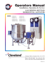
FORCE/2 Wireless Upgrade Kit Installation Instructions
REMOTE ATTACHMENTS
Wireless
Retrot
Kit
Kit Includes
•Antenna •Antenna mount •Belt clip
•Hose mount •Installation instructions •Layout/drill template
•Lanyard •Mounting hardware •Plastic tie wraps
•Receiver •Transmitter
LENGTH
4-1/8”
WIDTH
2-1/4”
LENGTH
4-9/16”
WIDTH
2-5/8”
Transmitter
Size 4-1/8”L x 2-1/4” W x 3/4”H
Weight 3.2 oz. (92 g)
Power (2) 3 volt, type CR2450
Antenna Internal
RF Range 250’
Battery Life 40+ hours of use
Control 4 color coded, sealed push buttons
Indicator Red LED
Modulation FM
Receiver
Size 4-9/16”L x 2-5/8”W x 1-1/16” H
Weight 4.2 oz. (117 g)
Power 24VDC
Antenna External
1-800-666-1611
Hose mount Lanyard Belt clip

Effective 7/19/2010
Note: This wireless kit will only t on
those machines manufactured after
4/2005, see lower left hand corner of
the electrical panel for date code.
Installation Instructions
Part Number 21200
(115VAC ONLY)
Approximate install time
(1-2 hours)
Tools Needed
Electric drill, 3/16, 3/8, & 1/2”drill bit, #2 Phillips screwdriver, center
punch, hammer, wire cutter/stripper, Qty (2) 7/16”, Qty (1) 5/8” and Qty
(1) 11/16”open end wrenches, pliers, rubbing alcohol, clean rag, Qty (2)
2 x 4 x 12” wood pieces and a small at le.
CAUTION!
BEFORE PERFORMING ANY WORK, MAKE SURE
THE FORCE/2 IS NOT PLUGGED INTO AN
ELECTRICAL OUTLET OR INJURY MAY OCCUR!
Turn the Force/2 upside down as
shown.
Locate the circular connector on
the side of the electrical box as
shown. To remove, turn outer ring
of connector, counter clockwise,
pull gently to remove.
Using a #2 Phillips screwdriver,
remove the six screws holding the
electrical face panel on the ma-
chine. When nished, set aside the
screws for use during re-assembly.
Outer ring
Note: Requires two people.
S
T
E
P
1
S
T
E
P
2
S
T
E
P
3

During removal of electrical box
and panel, make sure to support the
electrical box as shown.
Slide the electrical panel through
opening in base as shown. Once
you have successfully guided the
electrical panel though the hole,
remove electrical box and panel.
Remove the clear circuit breaker
seal by turning counter clockwise.
Push circuit breaker through the
panel and set aside.
Use alcohol to clean the back of the
control panel, allow to dry. Apply
drill template as shown.
Before center punching panel, place
a 2 x 4 underneath electrical panel
for support. Center punch all (6)
drill point areas.
Pilot drill all (6) center punched
areas using the 3/16” bit, then drill
holes as indicated on the template.
When nished, de-burr all drilled
holes, remove template and clean
out any metal shavings which may
have fallen into electrical box.
Place the electrical box with the
panel facing up, lift the control
panel up and ip it to the left.
Note: Make sure to support the electri-
cal box while removing the two mounting
screws. When nished, set screws aside
for use during re-assembly.
S
T
E
P
4
S
T
E
P
5
S
T
E
P
6
S
T
E
P
7
S
T
E
P
8
S
T
E
P
9
S
T
E
P
10
S
T
E
P
11
S
T
E
P
12
Note: Circuit breaker shown
from back of electrical panel.
Hint: Use the two mounting holes
for alignment.
Carefully remove the electrical
panel as shown. Caution:Do not
pull on the wires! Using a #2 Phil-
lips screwdriver, remove the two
screws holding the electrical box,
see arrows.

Use alcohol to clean outside of
electrical box, allow to dry before
applying template as shown.
Drill pilot hole using 3/16” drill bit.
Next, drill out pilot hole using 1/2”
drill bit.
At this point, all holes should be
drilled in the electrical face plate,
as shown.
Re-install both circuit breaker and
seal into newly drilled hole in elec-
trical face plate, as shown. Install
the plastic plug into the original
circuit breaker hole. CAUTION: Do
not over tighten, hand tighten only!
At this point, all holes should be
drilled.The circuit breaker and plug
should also be installed
Next, locate the wireless receiver,
remote selector switch and antenna
mount as shown.
Front view of electrical panel: Se-
curing wireless receiver to electri-
cal panel.
Remove template and clean shav-
ings from electrical box and set
aside.
Note: If compressed air is available, blow
out all shavings.
Mount the wireless receiver to the
back of the electrical panel by slid-
ing the device underneath the wires
as shown. Secure wireless receiver
to the electrical panel by using a #2
Phillips screwdriver and the four
6-32 x 1/4” screws.
Note: do not over tighten.
S
T
E
P
13
S
T
E
P
14
S
T
E
P
15
S
T
E
P
16
S
T
E
P
17
S
T
E
P
18
S
T
E
P
19
S
T
E
P
20
S
T
E
P
21
Note: Circuit breaker shown
from back of electrical panel.

Install Remote Selector Switch
sticker over hole as shown and
mount Remote Selector Switch.
Secure switch using Toggle Switch
Seal. Tighten switch using a 5/8”
wrench and hold the back of the
switch to prevent rotation.
Using pliers, remove and discard
the black wire going from rocker
switch 1(Terminal 4) and remote
quick disconnect (Terminal 2+).
Locate the wire marked (C1) on the
remote selector switch and connect
it to rocker switch 1 (Terminal 4).
Locate the wire marked (U1) on the
remote selector switch and con-
nect it to, remote quick disconnect
(Terminal 2+).
Remove and discard the red wire
going from rocker switch 2, (termi-
nal 4) and remote quick disconnect
(Terminal 1+).
Locate the wire marked (C2) on the
remote selector switch and connect
it to, rocker switch 2 (Terminal 4).
Locate the wire marked (U2) on the
remote selector switch and con-
nect it to, remote quick disconnect
(terminal 1+).
The black wires at this point should
be on the right hand side of the
switch and the blank area on the
left, see below for details.
Selector
switch
S
T
E
P
22
S
T
E
P
25
S
T
E
P
26
S
T
E
P
27
S
T
E
P
28
S
T
E
P
29
S
T
E
P
30
S
T
E
P
24
Blank area
Wiring Section
Wiring diagram: Rocker switch 1 & 2,
Remote Quick Disconnect and Remote
Selector Switch.
Reference
Only
Remote
Selector
Switch
U3
C3
D3
U2
C2
D2
U1
C1
D1
Rocker
Switch 1
Rocker
Switch 2
Remote Quick
Disconnect
2+
1+
2-
1-
2
4
2
4
Black Red
Black
White
Red
S
T
E
P
23
Label
2
4
2
4
2
4
2
4
2
4
2
4
2
4
2
4
2
4
2
4
2
4
2
4
2
4
2
4
Note: Make sure to secure the toggle
switch with the seal.

Locate and disconnect the white
wire on the Remote Quick Discon-
nect (terminal 1-).
Locate the wire marked (U3) on the
remote selector switch and con-
nect it to remote quick disconnect
(terminal 1+).
Locate the white wire which was
removed in step 31. Using wire
cutters, cut off existing terminal
as shown. Using wire strippers,
strip the white wire back, 3/4”, see
photo. Next, attach the stripped
wire to the Wago terminal on C3
from the remote selector switch.
Locate the anged inlet for the
blower. Using a #2 Phillips screw-
driver, remove the black wire as
shown in picture 5 & 6
Locate the black wire on the wire-
less remote receiver. Twist together
the black wire from the anged
inlet and wireless remote receiver,
see picture 7 & 8.
Insert twisted wires into anged
inlet as shown. Using a #2 Phillips
tighten screw and verify the wires
are secure by gently pulling on
them.
Pic 5
BLACK WIRE
REMOVED
Pic 6
BLACK WIRE
Pic 7
Pic 8
Pic 1 Pic 3
Pic 2 Pic 4
WHITE WIRE
Pic 11
Pic 12
Locate the blower anged inlet.
Using a #2 Phillips screwdriver,
remove the white wire as shown.
See Picture 9 & 10
Locate the white wire on the wire-
less remote receiver. Twist together
the white wire from the anged
inlet and wireless remote receiver,
see picture 3 & 4.
Pic 9
Pic 10
WHITE WIRE
REMOVED
Note: Do not nick or cut off the wires!
Also, to achieve a good t you may need to
trim off excess wire.
Connecting Wago terminal on C3
Pic 1 = Opening connector
Pic 2 = Open, ready for wire
Pic 3 = Insert wire
Pic 4 = Close connector
Test pull wire connection
S
T
E
P
31
S
T
E
P
32
S
T
E
P
33
S
T
E
P
34
S
T
E
P
35
S
T
E
P
36
S
T
E
P
37
S
T
E
P
38
S
T
E
P
39
Note: May have to rotate circuit breaker to
tighten screw on ange.

Insert twisted wires into anged
inlet as shown. Using a #2 Phillips
tighten screw and verify the wires
are secure by gently pulling on
them.
At this point all electrical wiring
should be installed.
Locate antenna connector, remove
the nut and washer, keep sealing
washer in place as shown.
Nut
Washer
Sealing washer
Insert the antenna connector into
the side of the electrical box as
shown.
Next, slip the washer and nut over
the connector and hand tighten.
Once the washer and nut are hand
tight, tighten another 1/4-1/2 turn
to secure. Use both a 5/8” & 7/16”
wrench when tightening.
At this point, the antenna connec-
tor should be secure and not able to
rotate.
Carefully, tuck the bundle of wires
from the electrical box and panel
together. Lower the electrical box
assembly into the base of the ma-
chine as shown.
Once the electrical box has been
lowered into the base, gently turn
the electrical panel and feed though
the opening of the base as shown.
DO NOT FORCE OR PULL ON ELEC-
TRICAL PANEL!
Washer & Nut
nger tight
S
T
E
P
40
S
T
E
P
41
S
T
E
P
42
S
T
E
P
43
S
T
E
P
44
S
T
E
P
45
S
T
E
P
46
S
T
E
P
47
S
T
E
P
48
Note: May have to rotate circuit breaker to
tighten screw on ange.

Support the back of the electrical
box as shown.
While supporting the electrical box
align holes and install the (2) #6
screws from step 4 using a #2 Phil-
lips screw driver.
Once the electrical box is secured
to the base, re-attach the electrical
panel to the base using the (6) #8
screws from step 3.
Align circular connector to ange
receptacle on electrical box. Turn
the outer ring of the circular con-
nector clock-wise until it stops.
OUTER RING
TURN CLOCKWISE
TO TIGHTEN
Note: Outer ring of connector will not
tighten unless properly aligned!
At the airlock locate and remove
the 1/4” bolt as shown below using
(2) 7/16” open end wrenches.
Attach the antenna mount as
shown below using the same 1/4”
bolt & nut.
1/4” bolt
At this point, antenna mount should
be secure as shown.
Locate antenna mount as shown.
Attach one end of the cable to the
antenna mount on the electrical
box, as shown.
S
T
E
P
49
S
T
E
P
50
S
T
E
P
51
S
T
E
P
52
S
T
E
P
53
S
T
E
P
54
S
T
E
P
55
S
T
E
P
56
S
T
E
P
57
Note: When attaching cable, you will need
to align the connector, push in and turn
clockwise.
Antenna Section

Route cable underneath the agitator
mounting bracket, attach the other
end of the cable to the antenna, as
shown.
Plug in both the agitator and blower
power cords to the anged recep-
tacles on electrical panel.
Turn off the main agitator and
blower switches on the control
panel.
Push the (newly mounted) remote
selector switch up to activate the
wireless remote.
Push the main agitator and blower
switches to the on position.
Before attaching remote cord,
check to make sure that the remote
switch is in the off position, attach
remote cord.
Set the variable speed bypass
switch to on.
Turn the variable speed control to
100%.
To START machine, depress the
GREEN, blower and agitator
switches.
A
G
I
T
A
T
O
R
B
L
O
W
E
R
Note: When attaching cable, you will need
to align the connector, push in and turn
clockwise.
Note: The down position of the switch
activates the corded remote.
S
T
E
P
58
S
T
E
P
59
S
T
E
P
60
S
T
E
P
61
S
T
E
P
62
S
T
E
P
63
S
T
E
P
64
S
T
E
P
65
S
T
E
P
66
Wireless Remote Testing Section
Note: Steps 59-65 are intentionally right
side up for ease of viewing.
Agitator Mounting Bracket
Agitator Mounting Bracket
Antenna

PUSH UP
Push the (newly mounted) remote
selector switch down to activate the
wired remote.
To start machine, depress the
rocker switch to the blower “on”
position and the agitator to the
“on” position.
To STOP machine, depress the
RED, blower and agitator switches.
A
G
I
T
A
T
O
R
B
L
O
W
E
R
S
T
E
P
67
S
T
E
P
68
S
T
E
P
69 ON
Installation is Complete
Corded Remote Testing Section
PUSH DOWN

FORCE/2 Wireless Retrot System
Operation Instructions
Wireless Remote Operation:
Rev: 08/10
Attach the transmitter to the blowing hose, belt clip or lanyard (see
wireless remote congurations at bottom of page). At the electrical
panel, locate the remote selector switch, position the switch to the
wireless remote position “Up” (Fig 1), once the remote bypass switch
is in the wireless remote position, depress the main control switches
(agitator & blower) to the “on” position (Fig 2 & 3). DO NOT PLUG
IN STANDARD REMOTE CORD WHEN USING WIRELESS
FEATURE. Depress the Green buttons on the wireless transmitter
to start the motors. NOTE: The main panel switches must be in the
“on” position for the machine to operate. The operator located at the
machine may stop either motor by pushing the switch to the “off”
position.
Remote Cord Operation:
Attach the remote cord to the electrical panel (Fig 4). At the electri-
cal panel, locate the remote selector switch, position the switch to the
remote cord position “Down” (Fig 5), once the remote selector switch
is in the remote cord position, depress the main control switches (agi-
tator & blower) to the “on” position (Fig 6 & 7). Depress the rocker
switch on the remote to start the motors. NOTE: The main panel
switches (Fig 6 & 7) must be in the “on” position for the machine to
operate. The operator located at the machine may stop either motor by
pushing the switch to the “off” position.
L
A
N
Y
A
R
D
HOSE ATTACHMENT B
E
L
T
C
L
I
P
Wireless Remote Congurations
Fig 1
Fig 3
Fig 2
Fig 6 Fig 7
Fig 4
Fig 5
8-01-2010
Note: To preclude possible back ow of material going into the blower motor.
STARTING MACHINE, start the blower rst then the agitator. SHUTTING
MACHINE OFF, turn off the agitator then the blower.
Miscellaneous:
Transmitter battery: Qty 2, CR2450
Operation range: 250’
Doc: 21211
/