Important Notes to the [nstammer
1. Readall instructions contained in these installation
instructions before installing the wall oven.
2. Remove all packing material from the oven
compartments before connecting the electrical supply
to the wall oven.
3. Observe all governing codes and ordinances.
4. Besure to leavethese instructions with the consumer.
5. Oven door may be removed to facilitate installation.
6. THESE OVENS ARE NOT APPROVED FOR
STACKABLE OR SIDE-BY-SIDE INSTALLATION.
Important Note to the Consumer
Keep these instructions with your Owner's Guide for future
reference.
IMPORTANT SAFETY
[NSTRU S
Be sure your wall oven is installed and grounded
properly by a qualified installer or service
technidan.
• This wall oven must be electrkally grounded in
accordance with local codes or, in their absence,
with the Nationa[ EJectrica[ Code ANSJ/NFPA
No.70- tatest edition in United Sates, or with CSA
Standard C22.1, Canadian Electrical Code, Part 1, in
Canada.
Stepping, [eaning or sitting on the
door of this wall oven can resu[t in serious injuries
and can also cause damage to the wait oven.
Never use your wail oven for warming or heating
the room. Prolonged use of the wall oven without
adequate ventilation can be dangerous.
The electrical power to the oven must
be shut off while line connections are being made.
Failure to do so could result [n serious injury or
death.
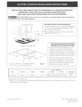
1. Carpentry
Refer to figure I or 2 for the dimensions applicable to
your appliance, and the space necessary to receive the
oven. The oven support surface may be solid plywood or
similar material, however the surface must be level from
side to side and from front to rear.
2. Electrical Requirements
This appliance must be supplied with the proper voltage
and frequency, and connected to an individual, properly
grounded branch circuit, protected by a circuit breaker or
fuse, having amperage as noted on the rating plate (the
rating plate is located on the side trim.
Observe all governing codes and local ordinances
1. A 3-wire or 4-wire single phase 120/240 or 120/208
Volt, 60 Hz AC only electrical supply is required on
a separate circuit fused on both sides of the line
(time-delay fuse or circuit breaker is recommended).
DO NOT fuse neutral. The fuse size must not exceed
the circuit rating of the appliance specified on the
nameplate. Only certain cooktop models may be
installed over certain builtqn electric oven models.
Approved cooktops and builtqn ovens are listed by
the MFG ID number (see the insert sheet included in
the literature package).
2. The single wall oven can consume up to 4000W at
240Vac; use a circuit breaker of 30 Amp with wire
gauge #8 AWG. The double wall oven can consume
up to 8000W at 240Vac; use a circuit breaker of 40
Amp with wire gauge #8 AWG.
NOTE: Wire sizes and connections must conform with
the fuse size and rating of the appliance in accordance
with the American National Electrical Code ANSI/NFPA
No. 70qatest edition, or with Canadian CSA Standard
C22.1, Canadian Electrical Code, Part 1, and local codes
and ordinances.
An extension cord should not be used
with this appliance. Such use may result in a fire,
electrical shock, or other persona[ injury. If you need
a longer power cord you can order for purchase a 10'
(3 m) power cord kit #903056-9010 by calling the Sears
Parts & Repair Center at 1-800-4-MY-HOME ®,
3. These appliances should be connected to the fused
disconnect (or circuit breaker) box through flexible
armored or nonmetallic: sheathed cable. The flexible
armored (:able extending from the appliance should
be connected directly to the junction box. The
junction box should be located asshown in Figure 1
or Figure 2 and with as much slack as possible
remaining in the cable between the box and the
appliance, so it can be moved if servicing is ever
necessary.
4. A suitable strain relief must be provided to attach
the flexible armored cable to the junction box.