Page is loading ...

_NSTALLAT_ON AND SERVICE MUST BE PERFORMED BY A QUAUF_ED INSTALLER.
_MPORTANT: SAVE FOR LOCAL ELECTRICAL _NSPECTOR'S USE.
READ AND SAVE THESE _NSTRUCT_ONS FOR FUTURE REFERENCE.
FOR YOUR SAFETY: Do not store or use gasotine or other flammabte vapors and tiquids in
the vicinity of this or any other appliance.
IMPORTANT INSTALLATION INFORMATION
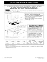
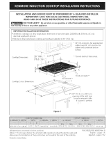
All electric cooktops run off a single phase, three-wire or four-wire cable, 240/208 volt, 60 hertz, AC only
electrical supply with ground.
Minimum distance between cooktop and overhead cabinetry is30" (76.2 cm).
For Standard Installation:
Cooktop Dimensions
30" Min. *
(76.2 cm)
* 30" (76.2 cm) rain. for
unprotected cabinet and
24" (6! cm) rain. for
cabinet with protected
bottom surface.
Cooktop Cutout Dimensions
C
4"X 8" (!0.2 cmx 20.3 cm)
openin to route armoured cable.
(89.2 cm)
Do not stide unit into cabinet cutout.
Protruding screws on the bottom of
unit may damage the bottom front
finish.
Figure 1
**Note: D & Eare critical to the proper installation
of the cooktop. D reflects the finished dimension.
Dueto the variation in countertop materials, it is
recommended to first undercut this dimension, and
then adiust it upon installation of the cooktop.
All dimensions are stated in inches and (cm).
Allow 2" (5 cm) space below the armoured cable opening to clear tile electric cable and
allow spacefor installation of tile junction box on the wall at the back of the cooktop.
P/N 318201418 (0407) Rev A
EngU-_ - pages 1-6
Espa_iol- pages 7-12

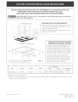
For Installation with the optional Stainless Steel Backsplash.
Cooktop Dimensions
2"(5.1 cm)
* 30" (76.2 cm) rain. for unprotected cabinet
and 24" (61 cm) rain. for cabinet with
protected bottom surface.
30"(7( 2 cm)
Min.*
***Note: Applies only in
caseof countertop j***
backwall.
4"X 8" (10.2 cm x 20.3 cm)
opening to route armoured cable.
Cooktop Cutout Dimensions
G
Do not slide unit into cabinet cutout,
Protruding screws on the bottom of unit
may damage the bottom front finish,
Figure 2
H
7¼
(18.4 cm)
**Note: I) & E are critical to the proper installation
of the cooktop. I) reflects the finished dimension.
Due to the variation in countertop materials, it is
recommended to first undercut this dimension, and
then adjust it upon installation of the cooktop.
All dimensions are stated in inches and (cm).
Allow 2" (5 cm) space below the armoured cable opening to clear the electric cable and
allow spacefor installation of the junction box on the wall at the back of the cooktop.

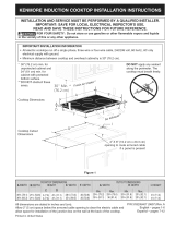
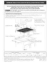
Overhead Cabinet Should Not Exceed a
Maximum Depth of 13" (33 cm)
30" (76,2 cm) Min,
Clearance Between the
Top of the Cooking
Platform and the Bottom
of an Unprotected Wood
or Metal Cabinet
24" (61 cm) Min, when
Bottom of Wood or Metal_ll_
Cabinet is Protected by
Not Less Than 1/8" Flame
Retardant Millboard
Covered With Not Less
Than No 28MGSSheet
Steel, 0.015" (0.4 ram)
Stainless Steel, 0024"
(0.6 ram) Aluminum or
0,020" (05 ram) Copper
10"
Cutout and Nearest ( 25,4 cm)
Combustible Surface
Above Countertop
18"
(45,7 cm)
It is not recommended to use
drawer underneath cooktop
25" Min,
Min,)
K Min, From Edge of
Cooktop to Nearest
Combustible Wall
(Either Side of Unit)
For dimensions E, F, G & H, see Table on page I_
Approximate Location
of Junction Box
_To eliminate the risk of burns or fire from
reaching over heated surfaces, cabinet storage space
located above the cooktop should be avoided. If cabinet
storage is provided, risk can be reduced by installing a
range hood that proiects horizontally a minimum of 7"
(17.8 cm) beyond the bottom of the cabinets.
MODEL K
36" (91.4 cm) 7_/2'' (19.I cm) I" (2.5 cm)
Figure 3 - COUNTERTOP CUTOUT OPENING

Important Notes to the Installer
1. Readallinstructionscontainedintheseinstallation
instructionsbeforeinstallingthecooktop.
2. Removeallpackingmaterialbeforeconnectingthe
electricalsupplytothecooktop.
3. Observeallgoverningcodesandordinances,
4. Besuretoleavetheseinstructionswiththeconsumer.
Important Note to the Consumer
Keep these instructions with your Useand Care Guide for
future reference.
Depth Adjustment Filler Kit #903051o9010
This cooktop isdesigned to replace existing unit. If the
depth of your countertop opening is bigger than 7Y4" (18.4
cm) and lessthan 8Y2" (21.6 cm) you (:an order a free filler
kit #903051-9010 by calling SearsParts & Repair Center at
1-800-4-MY-HOME@.
Optional Item Available:
A 9" (22.9cm) Stainless Steel Backsplash
Kit #903048-9010
This kit can be ordered for purchase through SearsParts
& Repair Center at 1-800-4-MY-HOME@.
IMPORTANT SAFETY
NS
Be sure your cooktop is installed and grounded
properly by a qualified installer or service
technkian.
These cooktops must be electrically grounded in
accordance with local codes or, in their absence,
with the National Electrical Code ANSJ/NFPA No.
70--latest edition in the United States, or with
CSA Standard C22.1, Canadian Electrical Code, Part
1, in Canada.
_The electrical power to the cooktop
must be shut off while line connections are being
made. Faiture to do so coutd resutt in serious injury
or death.
Provide Electrical Connection
Install the junction box under the cabinet and run 120/
240 or 120/208 Volt, AC wire from the main circuit
panel. NOTE: DO NOT connect the wire to the circuit
panel at this time.
Electrical Requirements
Observe all governing codes and local ordinances.
1. A 3-wire or 4-wire single phase 120/240 or 120/208
Volt, 60 Hz AC only electrical supply is required on a
separate circuit fused on both sides of the line (time-
delay fuse or circuit breaker is recommended). DO
NOT fuse neutral. The fuse size must not exceed the
circuit rating of the appliance specified on the
nameplate.
2. This unit can consume up to 1!,400W at 240 Vac. A
circuit breaker of 50 Amp with wire gauge #8AWG
shall be used.
NOTE: Wire sizesand connections must conform with
the fuse size and rating of the appliance in accordance
with the National Electrical Code ANS!/NFPA No. 70-
latest edition and local local codes and ordinances.
An extension cord must not be used
with this appJiance, Such use may result in a fire,
eJectricat shock, or other personat injury_
3. The appliance should be connected to tile fused
disconnect (or circuit breaker) box through flexible
armored or nonmetallic sheathed cable. The flexible
armored (:able extending from this appliance should
be connected directly to the grounded junction box.
The junction box should be located as shown in
Figure 3 with as much slack as possible remaining in
the cable between the box and the appliance, so it
can be moved if servicing is ever necessary.
4. A suitable strain relief must be provided to attach
tile flexible armored cable to the junction box.
Unpacking Instructions
1. Unpack and visually inspect the cooktop.
2. Be sure the bottle of cleaner conditioner packed in tile
literature bag is left where the user can find it easily. It
is important that the cerami(>glasscooktop be
pretreated before use. See Cooktop CJeaning and
Maintenance section in the Use and Care Guide.

Emectrica[ Connection
Connect the flexible armored cable that extends from
the surface unit to the junction box using a suitable
strain relief at the point the armored cable enters the
junction box. Then make tile electrical connection as
follows.
Electrical ground is required on this appliance.
This appliance is equipped with a
copper conductor flexible cable. If connection is
made to aluminum house wiring, use only spedal
connectors which are approved for joining copper
and aluminum wires in accordance with the
National Electrical Code and local codes and
ordinances, tmproper connection of aluminum
house wiring to copper leads can result in a short
circuit or fire. Follow the connector manufacturer
recommended procedure closely.
This appliance is manufactured with a white neutral
power supply wire and a frame connected green or bare
copper grounding wire.
DO NOT ground to a gas supply pipe.
DO NOT connect to eJectrical power suppJy until
appliance is permanentJy grounded. Connect the
ground wire before turning on the power.
Where local codes permit connecting the appliance-
grounding conductor to the neutraJ (white) wire
(see figure 4):
1. Disconnect the power supply.
2. In the circuit breaker, fuse box or junction box,
connect appliance and power supply cable wires as
shown in figure 4.
Cable from Power Supply
White Wire
(Neutral)
Red
Wires
Wires
Box
(Neutral)
Ground Wire U.L.-Listed Conduit
'Bare or Green Wire) Connector (or CSA listed)
Cable from appliance
Figure 4
3-WtRE GROUNDED JUNCTtON BOX
You may not ground the cooktop
through the neutral (white} wire if cooktop is used
in a new branch circuit installation (!996 NEC),
mobile home, recreational vehicle, or where local
codes do not permit grounding through the neutrat
(white) wire. When grounding through the neutral
(white} wire is prohibited, you must use a 4-wire
power suppJy cable. See Figure 5. Failure to heed
this warning may resutt in electrocution or other
serious personat injury.

If cooktop is used in a new branch circuit
installation (!995 NEC), mobile home, recreational
vehkle, or where toca! codes DO NOT permit
grounding through the neutral (white) wire (see
figure 5):
1. Disconnect the power supply.
2. Separate the green (or bare copper) and white
appliance cable wires.
3. In the circuit breaker, fuse box or junction box:
connect appliance and power supply cable wires as
shown in figure 5.
Cable from Power Supply
Ground Wire
Red
Ground Wire
(Bare or Green
Wire)
Wires
]
Black
Junction Box
Conduit
Connector (or CSA listed)
Cable from appliance
Figure 5
4-WIRE GROUNDED JUNCTION BOX
If connecting to a 4°wire power supply
cable electrical system, the appliance frame
connected ground wire MUST NOT be connected to
the neutral wire of the 4-wire electrical system.
NOTE TO ELECTRICIAN: The armored cable leads
supplied with the appliance are CSA-recognized for
connection to larger gauge household wiring. Tile
insulation of the leads is rated at temperatures much
higher than temperature rating of household wiring. The
current carrying capacity of the conductor is governed by
tile temperature rating of the insulation around the wire,
rather than the wire gauge alone.
Cooktop Installation
1. Visually inspect the cooktop for damage.
2. If you are installing the optional Stainless Steel
backsplash, first fix it at the back of the cooktop using
the screws supplied with the Kit and follow the
instructions attached.
3. Set the cooktop into the countertop cutout.
NOTE: Do not use caulking compound; cooktop should
be removable for service when needed.
Checking Operation
Refer to the Use and Care Guide for operation.
Do not touch cooktop glass or elements.
They may be hot enough to burn you.
Model and Serial Number Location
Tile serial plate is located under the cooktop.
When ordering parts for or making inquires about your
cooktop, always be sure to include the model and serial
numbers and a lot number or letter from tile serial plate
on your cooktop.
Before You Call for Service
Read the Before You Call for Service Checklist and
operating instructions in your Use and Care Guide. It
may save you time and expense. The list includes
common occurrences that are not the result of defective
workmanship or materials in this appliance.
Refer to your Use and Care Guide for Searsservice
phone numbers, or call 1-800-4-MY-HOME ®.
/