Power Probe II User manual
- Category
- Cable network testers
- Type
- User manual
This manual is also suitable for

Instructions
for ECT and
Power Probe
www.powerprobe.com

2
www.powerprobe.com
INTRODUCTION
Thank you for purchasing Power Probe products.
The Power Probe is the best professional electrical tester for reducing diagnostic time in 6 to 24 volt automotive electrical
systems. After a simple hook-up of the Power Probe to the vehicle's battery, the automotive technician can determine at a
glance at the red/green LED indicator, if a circuit is positive, negative or open without reconnecting hook-up clips from
one battery pole to the other. The Power Probe switch allows the automotive technician to conduct a positive or negative
battery current to the tip for testing the function of electrical components without the use of jumper wires. And yes, it is
short-circuit protected. It tests for bad ground contacts instantly without performing voltage drop tests. It allows you to
follow and locate short circuits without wasting precious fuses. The Power Probe can also test for continuity with the
assistance of its auxiliary ground lead. With a flip of the power switch, you will know at a glance that your Power Probe is
functioning without running to the battery as you would otherwise have to do with simple test lights. The Power Probe's
long cable allows you to test along the entire length of the vehicle without constantly searching for ground hook-ups. If
you are not using the Power Probe now in your electrical testing, you are spending too much diagnosic time.
Before using the Power Probe please read the instruction book carefully.
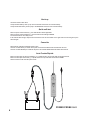
Warning!
When the Power Probe's switch is depressed battery current is conducted directly to the tip which may cause
sparks when contacting ground or certain circuits. Therefore the Power Probe should NOT be used around
flammables such as gasoline or its vapors. The spark of an energized Power Probe could ignite these vapors.
Use the same caution as you would when using an arc welder.
The Power Probe I & II and the ECT 2000 are NOT to be used with 110/220-volt house current, it is only for use
with 6-24-volt systems.
We thank you again for your purchase of Power Probe products and wish you much success in years to come.
INTRODUCCION
Agradecemos su compra de productros Power Probe.
Power Probe es un instrumento de pruebas eléctricas para reducir el tiempo de diagnóstico en sistemas eléctricos
automotrices. Una vez conectado el Power Probe a la batería del vehículo, el técnico automotriz debe determinar a
simple vista por medio del LED indicador, rojo/verde, si el circuito es positivo, negativo o está abierto, sin necesidad de
separar los cables o moverlos de un poste a otro de la batería. Ademas está protegido contra cortos circuitos. El Power
Probe permite al ténico automotriz realizar pruebas de alimentación negativa y positiva a través de la punta prueba, sin
necesidad de usar cables puentes. También prueba masas/tierras malas, instantaneamente sin desperdiciar fusibles. El
Power Probe puede probar por continuidad con la asistencia de un cable tierra/masa está provisto con el equipo y
conectado al mismo. Con un movimiento simple del interruptor de alimentación puede saber si el Power Probe funciona
sin necesidad de ir hasta la batería del vehículo. El cable extenso de Power Probe le permite a Ud. Probar y analizar el
sistema completo del vehículo eliminando la búsqueda constante de fuente y circuito de tierra en todo el vehículo. Si Ud.
No está usando el Power Probe en este momento para ubicar conecciones a tierra/masas en su diagnóstico, está
perdiendo mucho tiempo en realizar las pruebas. Antes de usar el Power Probe, por favor lea el manual de uso e
instrucciones cuidadosamente.
Aviso! ( Precaucion )
Cuando el interruptor del Power Probe es presionado, la corriente de la batería va directamente a la punta, lo
cuál puede producir chíspas cuando contacte tierra en ciertos circuitos. Por consiguiente el Power Probe, no
debería ser utilizado cerca de combustibles, como vapor de gasolina. Las chíspa producida en la punta del
Power Probe puede encender dichos vapores. Utilice las mismas precauciones usadas que cuando solde con
soldadura de arco.
El Power Probe I & II y el ECT2000 NO deben ser utilizados con 110/220 voltios de CA, estos equipos fueron
desarrollados para ser utilizados solamente con sistemas automotrices de 6-12 voltios unicamente.

3
Table of Contents
Power Probe I & II Instructions
Hook-up and quick self-test 4
Polarity testing 5
Continuity testing 6
Activating components out of vehicle's electrical system 7
Testing trailer lights and connections 8
Activating electrical components with positive (+) voltage 9
Activating electrical components with negative (-) voltage 10
Jumper lead feature 11
Checking for bad ground contacts 12
Following and locating short circuits 12
Using the light and tone (Power Probe II) 13
Parts and accessories for your Power Probe 14
"SMART" ECT 2000 instructions
15
The "SMART" transmitter 16
Connecting the "SMART transmitter 17
The "SMART" receiver 18
Locking the reception distance 19
Tracing short circuits 20
Tracing open circuits 21
Circuit wiggle & flex test 22
Power Probe warranty 23
IMPORTANT TIP: When powering-up components, you can increase the life
of your Power Probe switch if you first press the switch, then contact the tip
to the component. The arcing will take place at the tip instead of the contacts
of the switch.
Tabla de Contenido - Indice
Power Probe I & II
Conexiones y Auto Prueba Rápida 4
Probando Polaridades 5
Prueba de Continuidad 6
Activando Componentes fuera del circuito del vehículo 7
Probando luces y conexiones de trailers 8
Activando componentes eléctricos con positivo (+) voltaje 9
Activando componentes eléctricos con negativo (-) tierra 10
Función de Puente 11
Verificando por malos contactos de masa/tierra 12
Siguiendo y ubicando corto circuitos 12
Usando la luz el tono ( Power Probe II ) 13
Repuestos y Assesorios para su Power Probe 14
Power Probe Garantía 23

4
POWER PROBE I & II
Hook-up
Unroll the Power Probe cable.
Clamp the RED battery hook-up clip to the POSITIVE terminal of the vehicle's battery.
Clamp the BLACK battery hook-up clip to the NEGATIVE terminal of the vehicle's battery.
Quick self-test
Rock the power switch forward (+), the LED indicator should light RED.
Rock the power switch rearward (-), the LED indicator should light GREEN.
The Power Probe is now ready to use.
If the indicator did not light, depress the reset button of the circuit breaker on the right side of the housing and try the
self test again
Conexión
Desenrolle el cable de prueba del Power Probe.
Conecte el cable ROJO por medio de la pinza a la terminal POSITIVA de la batería del vehículo.
Conecte el cable NEGRO por medio de la pinza a la terminal NEGATIVA de la batería del vehículo.
Auto Prueba Rápida
Mueva el interruptor de potencia adelante (+), el (diodo emisor de luz) LED debe encenderse ROJO.
Mueva el interruptor hacía atrás
(
-
)
, el
(
diodo emisor de luz
)
LED debe encenderse VERDE
.
Ahora el Power Probe esta listo para usarse.

5
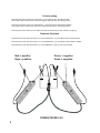
Green = negative
Verde = negativo
Red = positive
Rojo = positivo
POWER PROBE I & II
Polarity testing
Contacting the Power Probe tip to a POSITIVE (+) circuit will light the LED indicator RED.
(The Power Probe 2 audio feature will sound a high pitched tone when contacting positive)
Contacting the Power Probe tip to a NEGATIVE (-) circuit will light the LED indicator GREEN.
(The Power Probe 2 audio feature will sound a low pitched tone when contacting negative)
Contacting the Power Probe tip to an OPEN circuit will be indicated by the LED indicator not lighting.
Probando Polaridad
Contactando la Punta del Power Probe a un circuito POSITIVO (+) se encenderá el LED indicador ROJO.
Contactando la Punta del Power Probe a un circuito NEGATIVO (-) se encenderá el LED indicador VERDE.
Contactando la Punta del Power Probe a un circuito ABIERTO, el LED no será encencendido.

6
Green = continuit
y
Ve
r
de
=
co
n
t
in
u
i
dad
NO CONTINUITY
S
IN C
O
NTIN
U
IDAD
CONTINUITY
C
O
NTIN
U
IDAD
POWER PROBE I & II
Continuity testing
By using the Power Probe tip together with the auxiliary ground test lead, continuity can be tested on wires and
components that are disconnected from the vehicle's electrical system.
When continuity is present, the LED indicator will light GREEN.
Probando Continuidad
Por medio del uso de la punta del Power Probe en conjunto con el cable de masa auxiliar, la prueba de continuidad
puede ser realizada en cables y componentes que son desconectados del sistema eléctrico del vehículo.
Con continuidad existente, el indicator LED se encenderá de color VERDE.

7
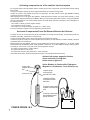
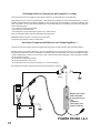
Activate fuel pumps, magnetic clutches,
starter solenoids, cooling fans,
blower motors, lights etc.
Activa Bombas de Combustilbe, Embragues
Magnéticos, Ventiladores, Luces, Motores, etc.
Connect the
negative auxiliary
clip
Conecte el Clip
Auxiliar Negativo
Press the power switch
forward to activate the
bulb
Presione el interruptor
hacía adelante para
activar el Bulbo
Contact the tip
to the positive
terminal of the bulb
Contacte la Punta
al terminal Positivo
del Bulbo
POWER PROBE I & II
Activating components out of the vehicle's electrical system
By using the Power Probe tip together with the auxiliary ground lead, components can be activated, thereby testing
their function.
Connect the negative auxiliary clip to the negative terminal of the component being tested.
Contact the probe to the positive terminal of the component, the LED indicator should light GREEN indicating
continuity through the component.
While keeping an eye on the green LED indicator, quickly depress and release the power switch forward (+). If the
green indicator changed instantly from GREEN to RED you may proceed with further activation. If the green indicator
went off at that instant or if the circuit breaker tripped, the Power Probe has been overloaded. This could happen for
the following reasons:
· The contact is a direct ground or negative voltage.
· The component is short-circuited.
· The component is a high amperage component (i.e., starter motor).
If the circuit breaker is tripped, reset it by depressing the reset button.
Activando Componentes Fuera Del Sistema Eléctrico del Vehículo
Por medio de uso de la punta del Power Probe combinada con el cable de masa auxiliar, componentes pueden ser
probados y activados, verificando su funcionamiento.
Conecte el clip del cable auxiliar a la terminal negativa del componente a probar.
Contacte la punta de prueba a la terminal positiva del componente. El LED deberá encenderse VERDE, indicando
continuidad dentro del componente.
Mientras observa el LED VERDE, presione y suelte rapidamente el interrutor hacía adelante (+). Si el LED, cambió
instantaneamente de VERDE a ROJO, puede proceder a reactivarlo. Si el LED VERDE se apagó y saltó el fusible,
se produjo un corto circuito. Esto pudo ocurrir por las siguientes razones:
· El contacto es masa directa o voltaje negativo.
· El componente está en corto circuito.
· El componente es de muy alto amperaie (ei.. motor arranque).
Si el fusible térmico saltó, reseteelo presionando el botón en la parte lateral del Power Probe.

8
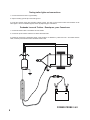
POWER PROBE I & II
Testing trailer lights and connections
1. Connect the Power Probe to a good battery.
2. Clip the auxiliary ground clip to the trailer ground.
3. Probe the contacts at the jack and apply voltage to them. This lets you check the function and orientation of the
trailer lights. If the circuit breaker tripped, reset it by depressing the reset button.
Probando Luces de Trailers - Remolques y sus Conexiones
1. Conecte el Power Probe a una batería en buen estado.
2. Conecte el clip de la masa auxiliar a una buena tierra del trailer.
3. Pruebe las conexiones y aplíqueles voltaje. Esto permite a Ud. identificar y ubicar las luces. Si el fusible térmico
salta, reseteelo presionando el botón lateral del Power Probe.

TRICK: When powerin
g
-up
components,
y
ou can increase the life
of
y
our Power Probe switch if
y
ou first
p
ress the switch, then contact the ti
p
to
the component. The arcin
g
will take
p
lace at the ti
p
instead of the contacts
o
f th
e
s
wit
c
h
.
MA
ÑA: Cuando se activan
com
p
onentes, es
p
osi
b
le extender la
vida del interru
p
tor del Power Pro
b
e, si
Ud. primero presiona el interruptor
y
des
pu
és contacta el componente. El
arco voltaico
(
c
h
íspa )
acu
rrirá en la punta
de
p
rue
b
a
.
POWER PROBE I &II
Activating electrical components
To activate components with positive (+) voltage:
Contact the probe tip to the positive terminal of the component, the LED indicator should light GREEN.
While keeping an eye on the green indicator, quickly depress and release the power switch forward (+). If the green indicator changed
instantly from GREEN to RED you may proceed with further activation. If the green indicator went off at that instant or if the circuit breaker
tripped, the Power Probe has been overloaded. This could happen for the following reasons:
· The contact is a direct ground.
· The component is short-circuited.
· The component is a high current component (i.e., starter motor).
If the circuit breaker tripped, reset it by depressing the reset button.
Warning: Haphazardly applying voltage to certain circuits can cause damage to a vehicle's electronic components. Therefore, it is strongly
advised to use the correct schematic and
diagnosing procedure while testing.
Activando Componentes Eléctricos con (+) Voltaje
Para activar componentes con Voltaje (+):
Contacte la punta del probador en la terminal positiva del componente. El LED indicador debe encenderse VERDE. Mientras observa el
indicador LED VERDE, presione rapidamente el interruptor hacía adelante (+). Si el indicador, cambia instantaneamente de VERDE o
ROJO, Ud. puede proseguir con otras pruebas. Si el indicador VERDE se apaga y salta el fusible térmico, el circuito está en corto. Esto
puede suceder por las siguientes razones:
· El contacto es una masa/tierra directa.
· El componente está en corto circuito.
· El componente es de alta corriente ( ej. Motor de arranque )
Si el fusible térmico saltó, reseteelo presionando el botón lateral del Power Probe.
Precaución: Aplicar voltaje directo a ciertos circuitos puede producir daños irreversibles a componentes electrónicos del vehículo. Por
consiguiente es recomendable que sean usados procedimientos correctos de diagnóstico y diagramas esquemáticos, durante el
procedimiento de diagnóstico.
M
o
t
or
9

10
POWER PROBE I & II
H
o
rn
C
laxo
n
De
p
ress the rocke
r
s
wi
tc
h r
ea
rw
a
r
d
to
g
round the horn
.
P
r
es
i
o
n
e
el
intrerruptor para
act
iv
a
r
e
l Cl
a
x
o
n
.
Activating electrical components with negative (-) voltage
Contact the probe tip to the negative terminal of the component, the LED indicator should light RED.
While keeping an eye on the red LED indicator, quickly depress and release the power switch rearward (-). If the red
indicator changed instantly from RED to GREEN you may proceed with further activation. If the green indicator went
off at that instant or if the circuit breaker tripped, the Power Probe has been overloaded. This could have happened
for the following reasons:
· The contact is a direct positive voltage.
· The component is short-circuited.
· The component is a high amperage component (i.e., starter motor).
If the circuit breaker tripped, reset it by depressing the reset button.
WARNING: With this function a vehicle's fuse can be blown
or tripped if grounding the contact in series with it.
Activando Componentes Eléltricos con Voltaje Negativo (-)
Contacte la punta de prueba a la terminal negativa del componente, el LED indicador debe encenderse ROJO.
Mientras observa el indicador LED ROJO, presione rapidamente el interruptor hacia atrás (-). Si el indicador ROJO
cambia instantaneamente de ROJO a VERDE Ud. puede proceder con las pruebas. Si el indicador VERDE se apaga
y salta el fusible térmico indica un corto circuito o que el Power Probe fué sobrecargado. Ésto pudo haber sucedido
por las siguientes razones:
· El contacto es Volaje Positivo Directo.
· El componente está en corto circuito.
· El componente es de mucho flujo de amperios ( ej., motor de arranque ).
Si el fusible térmico saltó, resételo presionando la tecla ubicada en el lateral.

11
POWER PROBE I &II
Motor
P
o
s
i
t
i
v
e
c
u
r
r
e
n
t
i
s
n
o
w
f
l
o
w
i
n
g
d
i
r
e
c
t
l
y
t
h
r
o
u
g
h
t
h
i
s
l
e
a
d
L
a
c
o
r
r
i
e
n
t
e
p
o
s
i
t
i
v
a
a
h
o
r
a
f
l
u
y
e
d
i
r
e
c
t
o
p
o
r
e
s
t
e
c
a
b
l
e
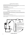
Positive hook-up clip hangs loose.
Clip positivo (ROJO) suelto.
e
s
t
a
c
i
v
a
d
o
e
e
l
a
.
a
n
d
a
t
i
v
a
t
i
n
t
h
r
e
l
a
y
.
Jumper lead feature
The Power Probe negative battery hook-up lead and auxiliary ground lead are connected directly through the Power
Probe. By leaving the positive hook-up disconnected from the vehicle's battery, the Power Probe can be used as a
long jumper lead.
Be careful to avoid short circuits and overloading when
using this jumper function. The leads, in this config-
uration, are NOT protected by the Power Probe's circuit
breaker.
Función de Puente
El cable negativo de batería y el auxiliar del Power Probe están conectados directamente a través del mismo Power
Probe. Si dejamos el cable y pinza positivo (+) desconectados en la batería del vehículo, el Power Probe puede ser
usando como un puente.
Tenga cuidado y evite cortos circuitos y sobre carga cuando use función de puente. Los cables, al ser conectados
como se muestran, el fusible no protége.

12
POWER PROBE I & II
Checking for bad ground contacts
Probe the suspected ground wire or contact with the probe tip.
Observe the green LED indicator.
Depress the power switch forward then release.
If the LED indicator changed from GREEN to RED, this is not a true ground.
If the circuit breaker tripped, this circuit is more than likely a direct ground. Keep in mind that high current components
such as starter motors will also trip the circuit breaker.
Following and locating short circuits
In most cases a short circuit will appear by a fuse or a fusible link blowing or a protection device tripping (i.e., a circuit
breaker). Here is the best place to begin the search.
Remove the blown fuse from the fuse box.
Use the Power Probe tip to energize each of both contacts in the fuse box. The side which trips the Power Probe
circuit breaker is the shorted circuit. Take note of this wire's identification code or color. Follow the wire as far as you
can along the wiring harness, for instance if you are following a short in the brake light circuit you may know that the
wire must pass though the wiring harness at the door sill. Locate the color-coded wire in the harness and expose it.
Probe through the insulation of the wire with the Power Probe tip and depress the power switch forward to energize
the wire. If the Power Probe circuit breaker tripped you have verified the shorted wire. Cut the wire and energize
each end with the Power Probe tip. The wire which trips the Power Probe circuit breaker again will lead you to the
shorted area.
Follow the wire in the shorted direction and repeat this process until the short is located.
For more information on short circuit tracing see pages 20 of this instruction booklet.
Buscando Malos Contactos de Masa/Tierra
Pruebe la masa/tierra que sospecha con la punta de prueba. Observe el indicador LED VERDE. Presione el
interruptor hacía adelante y suéltelo. Si el indicador LED cambia de VERDE a ROJO, esta no es una tierra
verdadera. Si el fusible térmico sálta, el circuito está directo a masa/tierra. Mantenga en mente que ciertos
componentes de alto flujo de corriente, como los motores de arranque, pueden hacer saltar el fusible térmico.
Siguiendo y Ubicando Cortos Circuitos
En la mayoría de los casos un corto circuito de identificará por in fusible quemado ( ej., un fusible térmico ). Este es
el lugar mas conveniente para comenzar.
Remueva el fusible quemado de la caja de fusibles.
Use la punta del Power Probe para energizar cada lado del fusible. El que haga saltar el fusible térmico del Power
Probe es el lado del corto circuito. Tome nota e identifique el color del cable con el corto. Siga el cable lo mas lejos
que pueda en el arnés, por decir si Ud. sigue un corto circuito en las luces de frenos, puede saber si está
atravesando por detrás de un panel. Ubique el cable acorde al color y expóngalo. Toque con la punta del Power
Probe y presione el interruptor hacía adelante (+). Si el fusible del Power Probe salta, Ud. acaba de indentificar
donde se encuentra el corto circuito. Corte el cable y energice cada lado, uno a la vez. El lado que haga saltar el
fusible otra vez es donde está el corto circuito. Siga el cable en la dirección del corto circuito, y repita esta operación
hasta encontar el punto donde está ubicado el corto circuito.

13
POWER PROBE II
Audio Tone
Audio Tone
On-Off Button
Audio Tone
Indicator
POSITIVE = CONSTANT TONE
NEGATIVE = PULSING TONE
POSITIVO = TONO CONSTANTE
NEGATIVO = TONO PULSANTE
Using the light and tone (Power Probe II)
Usando La Luz y Tono ( Power Probe II )
The Power Probe II has the option of a light and tone.
Once connected to a good battery, the light and the tone
will be activated.
The light illuminates the area you are testing and is a
great asset for seeing in dark areas.
The tone feature enhances the polarity signal. When the
tip is contacted to a positive circuit, a high pitch tone will
sound off. When the tip is contacted to a negative circuit,
a low pitch tone will sound off. The tone can be toggled
on or off by pressing the audio tone on-off button.
En la parte trasera del Power Probe II hay dos
interruptores deslizantes. Uno es para encender y
apagar la luz de iluminación para mediciones y el otro
enciende y apaga el tono audible.
La luz o LED ilumina el área de prueba y es de gran
utilidad cuando se realizan mediciones en cajas de
fusibles y tableros.
El tono audible ayuda a determinar la polaridad del
circuito. El tono será pulsante indicando un circuito
negativo y un tono constante cuando es circuito positivo.
Esto elimina la necesidad de observar el LED
continuamente.
Light
LUZ

14
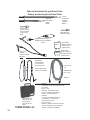
POWER PROBE I & II
Parts and accessories for your Power Probe
Partes y accessories para su Power Probe
Hook-up clip
assembly
Con
j
unto de Pinzas
PN
0
12
S
E
T
Extension lead:
20 ft.
Cable Extensión
20 ft. ( 6 mts )
PPEXT20
9 inch tip
Punta Prueba
9 pulgadas
( 228,6mm )
PN006L
Regular tip
Punta Prueba
Regular
PN006
Extending your
Power Probe lead
is a snap with the
20 ft. lead extension.
Extensión Disoponibles
20' para su Power Probe
Circuit breaker
(Requires soldering)
Fusíble Térmico
( Reguire soldar )
PN004
PN005
Rocker switch
(Requires soldering)
Interruptor Temporario
( Reguire soldar )
Red/Green LED
(Requires soldering)
LED ROJO/VERDE
( Reguire soldar )
PN009
Bright White LED
(Requires soldering)
Cigarette lighter adapter
Adaptador para el encendedor
PPCLA
Blow mold case for
Power Probe I & II
Estuche para el
Power Probe I & II
PN021
PPACC01
Accessories can also be purchased in a kit.
Kit includes:
PN021 - Case
PPEXT20 - 20ft extension cable
PPCLA - Cigarette Lighter adapter
PN006L - 9" extension probe
PPACC01
Los accesorios también pueden ser
Comprados en un conjunto (kit)
El Conjunto (kit) incluye:
PN021 - Estuche
PPEXT20 - Cable de extensión de 20 pies
PPCLA - Adaptador para el encendedor
PND06L - Probador de 9 pulgadas

15
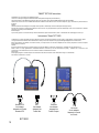
ECT-2000
R
EURO
GBC
POWER
PROBE
European
fuse adapter
Adaptador de
Fusible Europeo
ATO
POWER
PROBE
Standard ATO
fuse adapter
Adaptador de Fusible
Standard ATO
MINI
POWER
PROBE
Mini
fuse adapter
Adaptador de
Fusible Mini
Universal
circuit adapter
Adaptador Universal
de Circuito
"SMART" ECT 2000 instructions
Congratulations on your purchase of the "SMART" ECT 2000.
You are now on the way to finding those SHORT and OPEN circuit problems with greater speed and efficiency.
The advanced features of the "SMART" ECT 2000 put it above any of the others. It's programmed digital intelligence makes the unit "SMART".
The ECT 2000 consists of two units. A "SMART" transmitter and a "SMART" receiver with four of the most common adapters to get you connected to any electrical circuit on
the vehicle.
Warranty:
The Power Probe ECT 2000 undergoes a strict quality control inspection for workmanship, function and safety before leaving the factory.
From the date of purchase we will warranty the Electronic Circuit Tracer for one year against defects in parts and workmanship. In the event of a malfunction or defective
unit, please call or write your Power Probe dealer.
Technical Support
If you have any questions or comments about your Power Probe instrument, please call Power Probe, toll free: 1-800-655-3585. We will be happy to hear from you.
Instrucciones "Smart" ECT 2000
Le felicitamos en su compra del "Smart" ECT 2000. Usted esta en camino a encontrar esos problemas de corto circuitos y circuitos abiertos, de forma eficiente y rápida.
Los rasgos característicos avanzados del "Smart"ETC 2000 lo sitúan por encima de cualquier otro. Su programación digital inteligente hace la unidad "Smart".
El ETC 2000 consiste de dos unidades. Un Transmisor "Smart" y un receptor "Smart" con cuatro de los adaptadores más comunes, para permitir su conexión a cualquier
circuito eléctrico en el vehículo.
Garantía:
EL Power Probe ETC 2000 pasa por una estricta inspección de control de calidad en su fabricación, funcionamiento, y seguridad antes de salir de la factoría.
Desde el día de su compra, garantizaremos el Rastreador Electrónico de Circuitos por un año contra defectos en piezas y fabricación. En el evento de un mal
funcionamiento o una unidad defectuosa, favor de contactar o escribir a su distribuidor Power Probe.
Apoyo Técnico:
Si tiene al
g
una pre
g
unta o comentario respecto a su instrumento Power Probe, favor llamar a Power Probe libre de car
g
os al: 1-800-655-3585.
Nos sentiremos contentos en oír de usted.
POWER
PROBE

16
ECT-2000
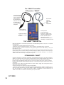
LED Indicators
In
d
i
cado
r
es
LE
D
Audio Speaker
for tone indication.
High tone = OPEN circuit
Low tone = SHORT circuit
Bocina de Audio para la
indicación por tono.
Tono Alto = Circuito Abierto
Tono Bajo = Circuito en Corto
Ground lead needs
to be connected to
chassis ground for
proper function.
El cable de tierra
debe ser conectado
al chasis para un
funcionamiento
apropiado.
Twin lead for
adapters
Cable doble
para
adaptadores
To
gg
le Tone Switc
h
Interru
p
tor acodad
o
de tono
THE "
S
MART" TRAN
S
MITTE
R
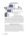
When the transmitter is connected and powered up, it will automatically detect for an open or a complete
circuit to ground.
The OPEN CIRCUIT LED indicates that the circuit is open.
The SHORT CIRCUIT LED indicates that the circuit is shorted (or grounded through a compenent).
When first initialized, the audio tone default is off. By depressing the TOGGLE TONE button you can cycle
the audio tone on or off.
When the transmitter is on, a signal transmits along the circuit. The signal transmits through plastic panels,
carpet, molding, etc. The signal is picked-up and detected with the "SMART" receiver. You can also pick up a
signal through the self-test area on the face of the "SMART" transmitter allowing you to confirm the
"SMART" ECT 2000 is hooked up correctly and ready to use.
El TRANSMISOR "SMART"
Cuando el transmisor es conectado y energizado, este primeramente pasa por un ciclo de auto prueba y
detecta las condiciones del circuito. Usted lo escuchara durante la auto prueba, emitiendo tonos auditivos
bajos, altos, bajos, altos, y vera los indicadores LED alternado entre corto y abierto respectivamente.
El LED de CIRCUITO ABIERTO (OPEN CIRCUIT) o un tono alto (2kHz) indica que el circuito esta abierto.
El LED de CIRCUITO EN CORTO (SHORT CIRCUIT) o un tono bajo indica que el circuito esta en corto (o
aterrizando).
Inicialmente el tono auditivo estará desactivado. Al oprimir el botón "Toggle Tone" usted puede activar o
desactivar la función de tono auditivo.
Cuando el transmisor esta activado, una señal será transmitida
a través del circuito. La señal es transmitida a través de paneles plásticos, alfombras, molduras, etc. La
señal es recogida y detectada por el receptor "SMART". También usted puede captar una señal mediante el
área de auto prueba en la carátula del transmisor "SMART", permitiéndole a usted confirmar que el
"SMART" ECT 2000 esta conectado correctamente y listo para ser usado.
The "SMART" Transmitter
El Transmisor "SMART"

17
ECT-2000
POWER
PROBE
ATO
POWER
PROBE
FUSE
This black lead must always
be connected to ground
Este ca
b
le ne
g
ro de
b
e esta
r
conectado a tierra siem
p
r
e
Chassis ground / Aterrizado - Chasis
Short circuit to ground
Circuito en corto a tierra
This black lead must alwa
y
s be connected
to ground. Este ca
b
le ne
g
ro de
b
e esta
r
conectado a tierra siempre.
This green lead is the signal output. Connect
it directly to the circuit you want to trace.
Este cable ahora esta listo para
probar circuitos abiertos o en corto.
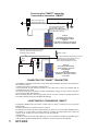
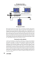
Figure A
Connecting to the vehicle's
fuse socket with fuse ada
p
ter
Figura A
C
o
n
ectado
a
l v
eh
ículo en el lugar del
f
us
i
b
l
e
v
ía una adaptador de fusible
Figure B
Connecting to the electrical
system using the "universal
circuit adapter"
Figura B
C
o
n
ect
ándose al sistema eléctrico
utilizando el "ada
p
tador universa
l
de circuito"
Black
Negro
Red
Rojo
Green / Verde
C
O
NNECTIN
G
THE "
S
MART" TRAN
S
MITTER
The "SMART" transmitter has two wires, the black lead with the alligator clip and the gray lead with the
twin terminal connector.
The black lead must be connected to chassis ground.
The gray lead with the twin terminal connector is to be used with one of the four adapters that are
provided with your ECT 2000.
One contact needs to be connected to positive vehicle battery voltage, the other contact connects to
the circuit being tested. (See figure B)
When connecting the twin connector (gray lead), there is no need to consider its polarity because the
ECT 2000 is polarity sensing and will adjust automatically.
CONECTANDO EL TRANSMISOR "SMART"
El transmisor "SMART" tiene dos cables, el cable negro con pinza y el cable gris con el conector de
doble terminal.
El cable negro debe ser conectado a tierra en el chasis.
El cable gris con conector de doble terminal es para ser usado con uno de los cuatro adaptadores que
se proveen con su ETC 2000. Un contacto debe ser conectado al voltaje positivo de la batería del
vehículo, el otro contacto se conecta al circuito que se este probando.
(Vea Figura B)
Cuando se conecta el conector doble (cable gris), no hay necesidad de considerar su polaridad ya que
el ECT 2000 se ajustara automáticamente mediante su función de detección de polaridad.
Connecting the "SMART" transmitter
Conectando el transmisor "SMART"

18
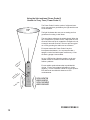
ECT-2000
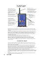
OPEN AND SHORT PICK-UP
Placing the surface of this reception
area parallel to the wire or circuit
allows the receiver to determine the
condition of the signal and gives you
the proper indication.
RECOJEDOR DE APERTURAS Y
CORTOS
Situando la superficie de esta ár
ea
de
recepción paralela al alambre o
circuito, permite que el receptor
determine la condición de la señal y le
da a usted una indicación apropiada.
WIRE HARNE
SS
PR
O
B
E
Insertin
g
the probe
g
ets
y
ou closer to the
wire if it is runnin
g
inside of a harness.
This is useful for open circuits onl
y.
So
n
da
de
Al
a
m
b
r
ado
de
Ar
n
és
In
se
rt
a
n
do
l
a
so
n
da
l
o
ace
r
ca
a
l
a
l
a
m
b
r
e
s
i
es
t
e
co
rr
e
de
ntr
o
de
u
n
a
r
n
és. Esto es
ú
til
p
ara circuitos abiertos solamente
.
DIRECTION TO SHORT
These two LEDs indicate the
direction to the short circuit.
Dirección al Corto
Estos dos LED's indican la
dirección hacia el circuito en
corto.
OPEN CIRCUIT
This LED indicates the
detection of the open circuit.
CIRCUITO ABIERTO
Este LED indica la detección
de circuito abierto.
POWER / SENSITIVITY
This switch will power up the
receiver and lock or unlock the
sensitivity threshold allowing you to
control the distance of picking up
the signal.
POTENCIA / SENSITIVIDAD
Este interruptor energizara el
receptor y fijara o liberara el ajuste
de sensitividad, permitiéndole a
usted controlar la distancia de
captación de señal.
THE "
S
MART" RE
C
EIVE
R
When first powered up, the "SMART" receiver will cycle through a self-test. It will beep low, high,
low, high and the LEDs will alternate accordingly. The unit is now ready to receive a signal from the
transmitter.
The left side of the "SMART" receiver contains the reception area or pick-up side. You are to place
this side in range of the transmitting circuit. The "SMART" receiver will pick up the signal and
determine if it is open or shorted. The receiver will beep repeatedly and increase in rate the closer
you get to the signal. You can also place the pick-up on the yellow self-test area of the SMART
transmitter to test the signal.
The DIRECTION TO SHORT indicator shows you the direction to ground.
The OPEN CIRCUIT indicator shows you that you are detecting an open circuit.
In the case of an open circuit being buried and shielded inside of a wire harness, the WIRE
HARNESS PROBE aids you in probing into the harness to get you closer to the open wire.
For longer battery life, the "SMART" receiver has an automatic 30 second shut-off when it is not
receiving a signal.
EL RECEPTOR "SMART"
Cuando se energiza inicialmente, el receptor "SMART" pasa por un ciclo de auto prueba. Hará un
sonido "Bip" bajo, alto, bajo, alto, y los LED's alternaran respectivamente. La unidad estará entonces
lista para recibir señales del transmisor.
El lado izquierdo del receptor "SMART" contiene un área de recepción o lado captador. Usted a de
poner este lado dentro de alcance del circuito transmisor. El receptor "SMART" captara la señal y
determinara si es una apertura o corto. El receptor comenzara su sonido "Bip" repetidamente y
aumentará el numero de repeticiones según usted se acerca a la señal. Usted también puede poner el
captador en el área amarilla de auto prueba del transmisor "SMART" para probar la señal.
El indicador de DIRECCION al CORTO le muestra a usted la dirección a tierra.
El indicador de CIRCUITO ABIERTO le muestra a usted que esta detectando un circuito abierto.
En caso que un circuito abierto este enterrado o acorazado dentro del arnés del alambrado, la SONDA
DE ALAMBRADO DE ARNES lo ayudara a usted sondear dentro del arnés para acercarlo al alambre
abierto.
Para alargar la vida de la batería, el receptor "SMART" tiene una función de apagado automático en
30 segundos cuando no esta recibiendo una señal.
The "SMART" receiver
E
l Rece
p
tor "SMART
"

19
ECT-2000
ATO
POWER
PROBE
FUSE
ATO
POWER
PROBE
FUSE
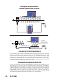
"SMART" transmitter
Transmisor "SMART"
Self test area
transmitting a signal
Área de auto prueba
transmitiendo una señal
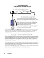
LOCKING THE RECEPTION DISTANCE
As you bring the receiver near the transmitting signal, the tone pulses will increase in p.p.m. (pulses per
minute). When you reach the desired distance, depress the POWER/SENSITIVITY button to lock the
reception at that distance. Moving the receiver away from your set threshold will stop the signal
indication. Moving the receiver back into the transmitting signal will resume the signal indication.
Depressing the "POWER/SENSITIVITY" button again will return the receiver back to the tone pulse
mode. The receiver is most sensitive in this mode and is great for roughly searching for a circuit. You
can use the distance lock to pinpoint your short or open circuit.
CERRANDO DISTANCIA DE RECEPCION
Al usted traer el receptor cerca de la señal transmitida, los pulsos de tono aumentaran en p.p.m.
(pulsos por minuto). Cuando usted alcance la distancia deseada, oprima el botón de POTENCIA /
SENSITIVIDAD para fijar la recepción a esa distancia. Al mover el receptor lejos de la distancia
establecida, detendrá la señal de indicación. Moviendo el receptor dentro del área de transmisión de
señal, reanudara la señal de indicación. Oprimiendo nuevamente el botón de "POTENCIA /
SENSITIVIDAD" regresara el receptor al modo operacional de pulso de tono. El receptor es más
sensitivo en este modo, y es grandioso para la búsqueda sencilla de un circuito. Usted puede utilizar la
función de cierre de distancia para localizar el punto de su corto o circuito abierto.
Locking the reception distance
Cerrando la distancia de rece
p
c
i
ó
n

20
ECT-2000
F
USE
AT
O
POWER
OWER
POWER
P
PROBE
No matter what side of the circuit
y
ou test, the RECEIVE
R
will indicate the direction to the short or
g
round
.
(
observe LED indicator
)
No im
p
orta el lado del circuito en
q
ue este
p
robando, el rece
p
tor indicara la direcc
i
ón
a se
g
uir hasta el corto o tierra
.
(
Observe el indicador LED
)
Signal drops at the
point of the short circuit.
La señal se cae en el
punto del corto en el circuito
TRACING SHORT CIRCUITS
To locate a short circuit, remove the blown fuse and connect the appropriate
adapter into the fuse socket. Connect the transmitter to the adapter. It may be
necessary to turn the vehicle's ignition switch on to activate the circuit. You can
see that the transmitter is working by hearing it cycle through its tests and observing its LED indicators. Take the
"SMART" receiver and turn it on. Move the "SMART" receiver around the circuit in question until you receive a signal.
Keep in mind that the SMART receiver is direction sensitive. This means that the signal reception is the strongest when
the OPEN & SHORT PICK-UP is parallel to the circuit. The pulsing signal will increase in PPM (pulses per minute) the
closer you get to the wire or circuit. The pulsing signal will decrease the further away you get from the circuit. If desired,
you can lock the threshold. (See LOCKING THE RECEPTION DISTANCE page 19) Follow the signal in the direction of
the arrow. When you come to the short, the receiver will stop beeping as you pass it. Search this area for the short. You
may find it useful to cut the wire and probe the circuit using a Power Probe circuit tester. (see "Following and locating
short circuits" on page 12). or you can reconnect the transmitter directly to the circuit. This may isolate other parallel
circuits that could be conducting some of the signal. In the case of an obstacle, such as a back seat blocking the way, try
opening the trunk and checking for a signal on that side. This may save you a lot of time in removing the obstacle. As
long as the receiver is receiving a signal, it will remain on. When it is not receiving a signal it will shut-off after 30
seconds.
RASTREANDO CIRCUITOS EN CORTO
Para localizar un corto en un circuito, remueva el fusible fundido y conecte el adaptador apropiado en el receptáculo del
fusible. Conecte el transmisor al adaptador. Puede ser necesario girar el interruptor de encendido para activar el
circuito. Usted puede ver que el transmisor esta funcionando escuchando su ciclo a través de sus pruebas y
observando sus indicadores LED's. Tome el receptor "SMART" y enciéndalo. Mueva el receptor "SMART" alrededor del
circuito en cuestión hasta que reciba una señal. Mantenga en mente que el receptor "SMART" es sensitivo a la
dirección. Esto significa que la recepción de la señal es más fuerte cuando el captador de cortos y aperturas esta
paralelo al circuito. La señal pulsante aumentara en PPM (pulsos por minuto) mientras mas cercano este al alambre o
circuito. La señal pulsante disminuirá mientras mas se aleje del circuito. Si se desea se puede cerrar el punto de
comienzo. (VEA CERRANDO LA DISTANCIA DE RECEPCION pagina 19). Siga la señal en la dirección de la flecha.
Cuando llegue al corto, el receptor parara el "Biping" al pasarse. Busque el corto en esta área. Usted puede encontrar
útil el corta el alambre y sondear el circuito utilizando un probador de circuito Power Probe. (Vea "Siguiendo y
localizando circuitos en corto" en la pagina 12). O usted puede reconectar el transmisor directamente al circuito. Esto
puede aislar otros circuitos paralelos que pueden estar conduciendo parte de la señal. En caso de obstáculos, tal como
un asiento trasero bloqueando el paso, trate abriendo el maletero (baúl) y continué probando la señal en ese lado. Esto
puede ahorrarle mucho tiempo al no remover el obstáculo. Mientras el receptor siga recibiendo la señal, este continuara
activo. Cuando no este recibiendo la señal, este se apagara después de 30 segundos
Tracing short circuits
R
ast
r
ea
n
do
co
r
tos
e
n
c
ir
cu
i
tos
Page is loading ...
Page is loading ...
Page is loading ...
-
 1
1
-
 2
2
-
 3
3
-
 4
4
-
 5
5
-
 6
6
-
 7
7
-
 8
8
-
 9
9
-
 10
10
-
 11
11
-
 12
12
-
 13
13
-
 14
14
-
 15
15
-
 16
16
-
 17
17
-
 18
18
-
 19
19
-
 20
20
-
 21
21
-
 22
22
-
 23
23


Power Probe II User manual
- Category
- Cable network testers
- Type
- User manual
- This manual is also suitable for
Ask a question and I''ll find the answer in the document
Finding information in a document is now easier with AI
in other languages
- español: Power Probe II Manual de usuario
Related papers
-
 Power Probe III User manual
-
Mastech PP319FTCGRN User manual
-
Power Probe PP3CSRED User manual
-
Power Probe PP3CSFIRE III User manual
-
 Power Probe PP3CSBLK User manual
-
 Power Probe PP3CSGRN User manual
-
Power Probe 319FTC-CARB III User manual
-
Power Probe PP3CSCARB III User manual
-
 Power Probe PP3CSBLU User manual
-
Power Probe PP3S User manual


Other documents
-
Autel Autel PowerScan PS100 Electrical System Diagnostic Tool Automotive Circuit Tester User manual
-
 AUTOOL AUTOOL Automotive Circuit Tester,Car Electrical System Diagnostic Tool User manual
-
ANCEL 13 User manual
-
 Positivo Twist 3 Hard reset manual
-
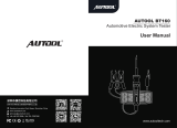 AUTOOL BT-160 User manual
-
-
Craftsman 82140 Owner's manual
-
-
Amprobe VPC-12 User manual
-
 Wavetek Meterman 5XL 10XL 15XL 16XL User manual


