Page is loading ...

www.autooltech.com
User Manual
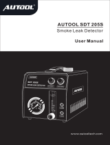
AUTOOL BT160
深圳市偶然科技有限公司
Shenhua Innovation Park, Baoan, Shenzhen, China
www.autooltech.com
+86-400 032 0988 / +86-755-27807580
深圳市偶然科技有限公司
深圳市光明新区长春南路中鹏程工业园
Automotive Electric System Tester

1 2
•
•
•
•
•
Introduction
Quickly check if a circuit is Positive, Negative or Open by probing it and observing the
RED or GREEN LED.
Quickly activate and check electric components by pressing power switch to (-) or (=)
position to determine their electronic and grounding status.
Test continuity of switches, relays, diodes, fuses and wires by connecting them between
the auxiliary ground lead and the probe tip and observing the GREEN LED.
Find faulty ground connections instantly.
Follow and locate short circuit.
This is overload protected by disconnecting circuit and beeping alarm to ensure safety of
user and battery. Before using this tester, please read the instruction manual carefully.
Automotive Electric System Tester
Thank you for purchasing Automotive Electric System Tester. It’s your best tool for testing
automotive electrical problems.
After simply hooking up two clips to the vehicle’s battery, user is able to operate it with below
key functions.
Only for use with 6-24V DC systems.
NOT designed to be used with 110/220 AC-volt house current and other over 24V DC
systems.
There are probably sparks on probe tip during it is used. DO NOT operate it in area with
combustible gas, dust and explosive conditions.
Check case and leads prior to using it. DO NOT use it when cracks or damage is visible.
Be careful of the sharp probe tip during using or putting away this tool. Keep out of reach
of children.
DO NOT attempt to open this tool, no serviceable parts are inside. Opening it voids the
warranty. All repairs should only be performed by authorized dealer.
Warning
•
•
•
•
•
•
Operation Voltage: 6-24V DC
Overload Protection: 10A
Lead Length: approximately 4M (13F)
Specification
•
•
•
Red LED: Positive voltage supplied or indicated.
Green LED: Negative voltage supplied or indicated.
Power Switch: Press button to “-” side to output positive voltage;
Press button to “=” side to output negative voltage.
Description
•
•
•
Operation Instruction
Unroll the leads.
Connect red clip to positive terminal of vehicle's battery.
Connect black clip to negative terminal of vehicle's battery.
Contact the probe tip to a positive (+), the LED should light RED.
Contact the probe tip to a negative (-), the LED should light GREEN.
Quick Self-Test
Unroll the leads.
Connect red clip to positive terminal of vehicle's battery.
Operation Instruction
Connect black clip to negative terminal of vehicle's battery.
Press button to “-” side , the LED should light RED.
Press button to “=” side , the LED should light GREEN.
Loose the button and contact the probe tip to positive terminal of battery , the LED should
light RED.
Loose the button and contact the probe tip to negative terminal of battery , the LED should
light GREEN.
Press button to “-” side , the LED should light RED. Then have the probe tip quickly
contact negative terminal of battery(there will be a little sparks), LED indicator turns to
GREEN with buzzer sounding.
Please complete self-test to determine tool’s functional availability prior to using it.
•
•
•
•
•
•
•
•
•
•
NOTE: DO NOT operate it in area with combustible gas, dust and explosive conditions.
NOT allowed to use it with AC and over 24V DC circuit.
Polarity Testing
This tool can test uncertain polarity of contact in the circuit of vehicle.
•
•
•
•
•
NOTE: DO NOT operate it in area with combustible gas, dust and explosive conditions.
NOT allowed to use it with AC and over 24V DC circuit.
Unroll the leads.
Connect red clip to positive terminal of vehicle's battery.
Connect black clip to negative terminal of vehicle's battery.
Connect auxiliary ground lead to one side of tested wire along with
probe tip connecting to the other side. When continuity is present,
the LED will light GREEN. If LED does NOT light up, NO continuity
present.
Continuity Testing
NOTE: DO NOT operate it in area with combustible gas,dust and
explosive conditions. NOT allowed to use it with AC and over 24V
DC circuit.
•
•
•
•

3 4
Unroll the leads.
Connect red clip to positive terminal of vehicle's battery.
Connect black clip to negative terminal of vehicle's battery.
Connect auxiliary ground lead to negative terminal of tested component.
Press button to (-) side with LED lighting RED. Contact the probe tip to positive terminal
of tested component to active the component. If LED turns to GREEN with buzzer
sounding, stop testing and check the component if defective or not, or rating current of
component is higher than that of this tester.
Testing Components Out of Vehicle’s Electrical System
•
•
•
•
•
NOTE: DO NOT operate it in area with combustible gas, dust and explosive conditions.
NOT allowed to use it with AC and over 24V DC circuit.
Testing Components in Vehicle’s Electrical System
Unroll the leads.
Connect red clip to positive terminal of vehicle's battery.
Connect black clip to negative terminal of vehicle's battery.
When component’s control switch is located at the side of positive terminal of component ,
press button to “-” side to have LED light RED. Contact probe tip to the positive terminal of
component. The component will be activated.
When component’s control switch is located the at side of negative terminal of component ,
press button to “=” side to have LED light GREEN. Contact probe tip to the negative
terminal of component. The component will be activated.
When it comes to check each little metal points in lamp’s socket , connect auxiliary ground
lead to ground of component. Then press button to “-” side to have LED light RED. Contact
probe tip to each metal points individually. The component will be activated.
•
•
•
•
•
•
If color of LED changes along with buzzer sounding, stop
testing and check the component if defective or not, or rating
current of component is higher than that of this tester.
•
NOTE: DO NOT operate it in area with combustible gas, dust
and explosive conditions. NOT allowed to use it with
AC and over 24V DC circuit.
The black clip and auxiliary ground lead are connected directly
through the unit. User can consider it as a long jumper test lead
by leave the red clip disconnected from the battery.
Jumper Lead Operation
NOTE: DO NOT operate it in area with combustible gas, dust
and explosive conditions. NOT allowed to use it with AC and
over 24V DC circuit.
Unroll the leads.
Connect red clip to positive terminal of vehicle's battery.
Connect black clip to negative terminal of vehicle's battery.
Press button to “-” side , the LED should light RED , and
positive voltage is supplied. Then have the probe tip quickly
contact negative terminal of component as close as possible,
LED indicator turns to GREEN with buzzer sounding, which
means it is well grounded. If NOT, the LED remains RED
without any buzzer.
Grounding Testing
For some components of which negative terminal is required to be well grounded for large
current flowing, this tester is a good tool to test their grounding.
•
•
•
•
NOTE: DO NOT operate it in area with combustible gas, dust
and explosive conditions. NOT allowed to use it with AC
and over 24V DC circuit.
Unroll the leads.
Connect red clip to positive terminal of vehicle's battery.
Connect black clip to negative terminal of vehicle's battery.
Press button to “-” side , the LED should light RED , and positive voltage is supplied.
Remove the blown fuse from the fuse box and begin tracking from two terminals of the
fuse socket. Use probe tip quickly contact wire. If LED lights GREEN with buzzer, short
circuit or overloading component appears in this side. Please note this wire’s color or
identification code. Follow the wire as far as you can along the wiring harness. Locate the
color-coded wire in the harness and expose it. Cut the wire. Follow the wire in the shorted
direction and repeat this process until the short is located. If there are components in the
following wire, check the components individually if good or not.
Short Circuit Following and Locating
In most cases short circuit or instant overload of component will lead to blown fuse or circuit
breaker tripping. This tester can search and locate the problem.
NOTE: DO NOT operate it in area with combustible gas, dust and explosive conditions.
NOT allowed to use it with AC and over 24V DC circuit.
•
•
•
•
•
/