Page is loading ...

Doc# M9053 • REV M (Nov 2020) Page 1 of 12
SM6100 VIBRATION INPUT MONITOR
Installaon Manual
0598
C US
The SM6100 is a versale protecon
instrument capable of measuring excesive
vibraon. In its standard conguraon, the
SM6100 is an economical single input vibra-
on monitor loaded with standard features
and packaged in an industrial grade housing.
Fully congured, the SM6100 provides for
machine control with oponal LCD readout,
real me remote operator interface via 4-20
mA and an external BNC (weather-proof
only) for easy analyst access to the buered
dynamic vibraon signal.
SPECIFICATIONS
Sensor External accelerometer, velometer or velocity transducer.
See opon ‘G’ in SM6100 Datasheet (doc # 1009514).
Signal Condioner Amplier/ integrator to obtain velocity or displacement
response. True RMS detecon.
Maximum Vibraon Limit 50 g, peak; 4 ips, peak. See opon “B” for vibraon ranges in
SM6100 Datasheet (doc # 1009514).
Buered Dynamic Signal (Vxducer) (gain X1) 2 Hz to 3000 Hz (-3 dB). Capable of driv-
ing 300 meters (1000 feet) of shielded cable (0.03uF max).
Sensor OK Indicator A green LED when illuminated indicates that the external
sensor is connected.
Alarm Limit(s) Single limit standard, second limit oponal, Adjustable from
-10% to 110% of range, 2% repeatability.
Trip Indicators Limit 1, amber LED; Limit 2, red LED
Limit Trip Delay Fully adjustable me delay of 1 - 15 seconds

Doc# M9053 • REV M (Nov 2020) Page 2 of 12
Triac Outputs 250 VAC, 1A, opcally isolated, eld selectable N.O. or N.C.
Factory set @ N.C. posion. Holding current 35 mA maxi-
mum at 25°C (60 mA at -40°C).
Oponal FET Output 50 VDC, 0.5A, Field Selectable N.O. or N.C. Factory set @ N.C.
Startup Trip Delay Standard delay is xed at 30 seconds. Oponal remotely
retriggerable startup delay adjustable from 1 - 30 seconds.
Oponal 4-20 mA Source
Output
4-20 mA proporonal to velocity or displacement. See op-
on “B” in SM6100 Datasheet (doc # 1009514). Zero and
Span calibrated ±2%. Non-linearity less than 2%. 600 ohms
max. load resistance.
Weight 2 Kg, (4.4 lbs).
Housing Cast aluminum: Explosion-proof / weather proof. Stud
mount: 1/2-14 NPT standard or oponal M20 X 1.5 straight
thread with jam nut. Other mounngs available.
Conduit connecons 3/4-14 NPT or M20 X 1.5 straight thread.
Input power 95 to 125 VAC, 190 to 250 VAC, 50/60 Hz, 5W max. or 20 to
28 VDC, 7W max. Power isolated from circuits.
Frequency Response (vel) ±3.0 dB 2 Hz to 3000 Hz
(disp) ±3.0 dB 2 Hz to 200 Hz
Temperature Limits No Display: -40°C to +85°C, -20°C to +85°C (ATEX) w/Display:
-10°C to +70°C
Output Sensivity vs
Temperature
Less than .05%/°C (calibrated at 25°C)
Alarm Test Alarm limit adjustment to below 0% of range causes triac/
FET actuaon.
Field Wiring Wire clamp type screw terminal block. Max. wire gauge: 14
AWG. 500 Vrms, circuit to case.
Hazard Rang See opon “D” in SM6100 Datasheet (doc # 1009514)
Environmental Rang NEMA 4/4X, IP 65
Electromagnec Compat-
ibility
CE tested to EN61326-1:2006.
Oponal Display 2 1/2 digit LCD. Window provided only with display version.
Reset Standard internal switch, remote N.O. contacts or oponal
external switch.
SPECIFICATIONS (connued)

Doc# M9053 • REV M (Nov 2020) Page 3 of 12
OUTLINE & DIMENSIONS
MECHANICAL INSTALLATION
Monitor Installaon
The Model SM6100 Monitor can be mounted in any convenient locaon where the display
can be viewed. Unit requires a tapped hole, see Opon F in SM6100 Datasheet (doc #
1009514) or use a Metrix model 7084 ange mount adapter.
If an NPT mounng stud is selected, the stud will ghten before the switch casing touches
the machine case. The SM6100 should be hand ghtened and then wrench ghtened to
bring the conduit connecons to the appropriate locaon. Studs with straight threads are
provided with a locking nut.
Special Condions for Safe Use:
Ambient Operang Temperature: -40°C to +85°C (model without display), -10°C to +70°C
(model with display)
Aprox. Weight:
272 g (0.6 lbs)
Units:
mm [in.]

Doc# M9053 • REV M (Nov 2020) Page 4 of 12
NOTE:
1) Diagrams show all available opons, see SM6100 Datasheet
(doc # 1009514) to verify opons on your parcular unit.
2) On Single Limit Models, use Load Limit Two (2) connecon.
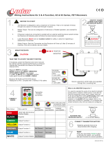
WIRING
Terminal Wiring
If you have selected the oponal display, the display circuit board must be removed (two
screws) to expose the terminal strips. The display board cable should not be disconnected.
Place the display board out of the way to allow wiring to the terminal strips. The display may
be reinstalled in any of the four possible orientaons.
Refer to gure 1 for wiring informaon. For incoming power and switch output(s) use ap-
proved wire of 14 AWG (1.5 sq. mm) or smaller.
For the current and dynamic signal outputs a shielded, twisted pair is recommended. By
convenon, the shield should be ed to common only at the receiver end. A cable consist-
ing of separate shielded twisted pairs can also be used. For the dynamic signal output the
capacitance of the cable run must not exceed .03 uF (typically 1000 feet).
Figure 1: Wiring Diagram (LCD opon not shown)
NOTE: On ATEX approved units, a locking set
screw must be loosened prior to lid removal.
Note: On ATEX installaons, a means for disconnecng power to the switch must
be provided. Also, the symbol signies a protecve earth terminal. For reset and
startup delay funcons, use a twisted pair to reduce electrical noise pickup.
CAUTION: Conduit seals are highly recommended to prevent the entry of moisture
into the switch. Moisture will damage the switch and void the warranty.

Doc# M9053 • REV M (Nov 2020) Page 5 of 12
Power Wiring
It is highly recommended that all power and triac/FET wiring be routed separately from the
external sensor, the dynamic signal and 4-20mA wiring in order to reduce AC/transient noise
pickup. The power required is indicated on the nameplate. The voltage supply must be
within the following limits:
24 VDC: 20 to 28 VDC
115 VAC: 95 to 125 VAC, 50/60 Hz
230VAC: 190 to 250 VAC, 50/60 Hz
Polarity does not need to be observed when wiring for DC power. The preferred method of
operaon is to connuously apply power to the SM6100. If power is to be applied as a part
of the machine startup sequence it is advisable to apply power to the SM6100 30 seconds
prior to starng the machine in order to allow the electronics circuits to stabilize. This is
parcularly important if the adjustable startup delay opon is ulized and the delay is set to
less than 20 seconds.
Alarm Limit Triac Output Wiring
The triac output(s) are electro-opcally isolated from each other, power, and the internal cir-
cuit. These are medium power devices with high immunity to electrical transients. If desired,
each triac can be supplied from an AC voltage source dierent from the main supply. The
triacs can be connected in series with the triacs of other units. See Fig. 2. Parallel connecon
of two switches doubles the triac holding (minimum load) current requirements. The maxi-
mum triac supply voltage is 250 VAC. The worst case triac leakage (o) current is 2 mA. The
maximum triac holding current is 35 mA at 25°C (60mA at -40°C) which requires that the relay
pull-in current have a greater value. Do not use a DC supply. The triacs can be set for NC or
NO operaon by posioning the Limit 1/Limit 2 switches accordingly.
FIGURE 2: Parallel connecon of two SM6100
A. Set each SM6100 for N.C. (normally closed) operaon. (See Fig. 1)
B. M2, M3 and remote reset contacts must be isolated
Alarm Limit FET Output Wiring (oponal)
The oponal FET limit output(s) provide a low leakage switch for DC inputs to PLC’s or other
devices. Do not use on an AC supply. Observe proper polarity when wiring the FET(s) (See
gure 1). Damage to the FET(s) will result from improper wiring. As with the triacs, the FET(s)
can be set for N.C. or N.O. operaon by posioning the Limit 1/Limit 2 switches accordingly.

Doc# M9053 • REV M (Nov 2020) Page 6 of 12
Limit Trip Delay
The base unit has an adjustable (1-15 sec.) limit trip delay. The vibraon level must be con-
nuously above the limit seng for the duraon of the me delay before the output devices
switch. The 4-20 mA output is not aected by this me delay. To reset the limit output
devices, the internal reset push-buon or the oponal external reset push-buon must be
pressed. Remote reset by a N.O. push-buon or momentary contacts may be made by wir-
ing to the remote reset terminals. Note that the vibraon level must be below the trip level
for the reset to funcon.
Startup Trip Delay
Some machines generate vibraon levels during startup which are higher than normal run-
ning levels. These high vibraon levels can exceed the Alarm Trip Limits which are set above
the normal running vibraon level. The standard SM6100 has a xed me delay which inhib-
its alarm trips for 30 seconds from the closing of the startup contacts.
An oponal adjustable startup trip delay (1-30 sec.) permits the Alarm Trip Limits to become
operave in less than 30 seconds. Protecon of machines with short startup mes can be
improved by ulizing the adjustable Startup Trip delay.
The Startup Trip Delay is triggered by closing a set of contacts (momentary or connuous)
connected to the startup terminals. The contacts must be opened before the internal startup
delay mer can be iniated again. Connecng these terminals to a set of isolated auxiliary
N.O. contacts in a motor starter is a method commonly used to iniate the startup trip delay.
The 4-20 mA current output is inhibited (set to 4.0 mA) during the startup trip delay.
Remote Reset Wiring (oponal)
If remote reset capability is desired, connect Reset terminals (see Figure 1) to a remotely locat-
ed, momentary N.O. push-buon switch. Observe hazardous area requirements if applicable.
External Sensor
The SM6100 requires the use of an external sensor. Refer to Opon G from SM6100 Data-
sheet (doc # 1009514) to determine the type of sensor required.
4-20 mA Current Source Output (oponal)
If the oponal 4-20 mA output is installed it may be connected to a remote receiver, as
shown on the wiring diagram (see Figure 1). This output is a current source (at 15VDC) and
requires no external loop power supply. Full scale current (20 mA) corresponds to the full
scale vibraon response marked on the face plate. A current of 4.0 mA represents a zero
vibraon condion. The maximum load resistance is 600 ohms. In high electrical noise loca-
ons a shielded, twisted pair cable is recommended.
FORMULA: X Full scale vibraon = Actual vibraon
EXAMPLE:
Measured mA Full Scale Vibraon Actual Vibraon
4.0 1.0 ips, peak 0.0 ips, peak
12.0 1.0 ips, peak 0.5 ips, peak
20.0 1.0 ips, peak 1.0 ips, peak
Measured mA - 4mA
20mA - 4mA

Doc# M9053 • REV M (Nov 2020) Page 7 of 12
Dynamic Outputs
The sensor (transducer) signal is available at the terminal block and is capable of driving a
cable with a capacitance of up to .03 uF (typically 300m/1000 feet). Longer runs with great-
er than .03 uF of capacitance can be used without the buer becoming unstable. However,
the frequency response will be reduced due to the increased capacitance.
RECEIVER CONFIGURATION / CALIBRATION
Signal Condioning Module Output: 4 - 20 mA Source Opon
The SM6100 can be factory congured to provide a 4 - 20 mA current source output pro-
poronal to the specied full scale vibraon response (velocity or displacement). Figure 3
shows suggested programming for a 4-20 mA receiver (PLC, DCS, monitor or computer).
Figure 3: 4-20 mA receiver suggested programming
Vibraon Switch Calibraon
The SM6100 has been factory calibrated to standards traceable to the U.S. Naonal
Instute of Standards and Technology (NIST). If the accuracy is in queson, the SM6100
output response can be compared (on an operang machine) with an independent vibra-
on measurement made at the external sensor in the same axis and at the same locaon
with a calibrated vibraon analyzer. Ensure that the analyzer is congured with the same
frequency response as the SM6100 and with the same unit of measure (i.e. ips pk.). To pre-
vent tampering, there are no user accessible adjustments available for eld recalibrang. If
recalibraon is required, the SM6100 should be returned to the factory for recalibraon to a

Doc# M9053 • REV M (Nov 2020) Page 8 of 12
Figure 4: Switch calibraon block diagram
Determining Output Voltage
If it is desired to determine either the acceleraon or velocity amplitude when one measure-
ment is unknown, the following formulas can be employed.
If g’s (A) are known and you wish to determine the velocity output:
If velocity is known and you wish to determine the displacement output:
If g’s (A) are known and you wish to determine the displacement output:
Where V = ips, peak, F = RPM, A = g peak, D = mils, peak-to-peak
USER ADJUSTMENTS
Limit Trip Delay
The Limit Trip Delay adjustment allows the user to set the me delay from 1 to 15 seconds.
This is useful in avoiding false trips from transient condions while the machine is running.
Adjustable Startup Trip Delay (oponal)
The oponal Startup Trip Delay adjustment allows the user to set the me delay from 1 to 30
seconds. This is useful in tailoring the Startup Trip Delay for a parcular machine’s startup
vibraon characteriscs.
traceable standard. In eld installaons, the calibraon should be veried at least once per
year. In test cell applicaons, depending upon the severity of handling, correct operaon
and calibraon should be veried each 90-180 days.

Doc# M9053 • REV M (Nov 2020) Page 9 of 12
Limit Sengs
The Limit Seng adjustment allows to set the vibraon levels at which a limit will trip. The ad-
justment has a range of -10% to 110% of the full scale vibraon level. A midscale adjustment
corresponds to a 50% vibraon level limit. Turning the adjustment to its minimum value (CCW)
allows the user to test the trip circuitry, including LED’s, me delays and triac (FET) switches.
The limit seng can be set precisely by measuring the limit voltage with a DVM. The test
points for measuring this voltage are labeled TP3 (Limit 2), TP4 (Limit 1) and COM (common).
The DC voltage represents a percentage of full scale. For example, .46 VDC would represent
a limit seng of 46% of full scale. This test should be performed with the machinery not
running or switch outputs by-passed.
Auto Reset
The switch outputs (triacs or FETs) are congured at the factory for latching operaon (Figure
5a). The switch outputs can be congured for non-latching operaon (Figure 5b) so they
automacally reset when the vibraon level falls below the alarm limit threshold. To do this,
remove power to the unit. Remove the transmier cover and the display board if present.
Refer to Figures 5a &5b (move both jumpers to the auto posion). Reassemble the display
board and transmier cover. The switch outputs will now reset when the vibraon level falls
below the alarm limits.
Figure 5a: Figure 5b:
Switch Output Congure as Switch Output Congure as Reset Opon
Latched Opon (factory default)
CAUTION: This test should be performed with the machinery turned o or switch
outputs by-passed. Aer tesng, reset the limits to the proper operaonal values.
Cauon: Aer tesng, reset the limits to the proper operaonal values.

Doc# M9053 • REV M (Nov 2020) Page 10 of 12
TROUBLESHOOTING
The unit appears to be funconing, but limit operaon is in queson.
a) Operaon of the limit triac/FET and the aached relay can be veried by toggling the NO/
NC switch.
b) The limit seng can be rotated to the minimum (-10%) seng in order to exercise all of
the limit control logic and trip delay circuits. The limit triac/FET should operate and the limit
LED should turn on aer the set trip delay expires. REMEMBER to return the limit seng to
the original posion aer this test.
c) If the LED is lit but the limit is not funconing, check to make sure the triac/FET load is
wired properly and power is present at the limit terminal block and relay.
The unit appears to be funconing, but the 4-20 mA operaon is in queson.
a) Ensure that the current loop is wired properly and that the total loop resistance does not
exceed 600 ohms. The Model SM6100 4-20 mA circuit is a current source. A voltage source
(power supply) must not be used in the circuit.
b) Verify current output with separate current meter connected in series with the 4-20 mA
output and the receiving instrument input. Verify the current is correct. Current output
with zero vibraon should be 4.0 mA. A 20 mA current represents full scale vibraon. Refer
to “Wiring: 4-20 mA Current Source Output”.
The unit does not respond to vibraon input during the rst few seconds of operaon.
The startup me delay circuit prevents the transmier from reacng to a vibraon input
during the startup delay me period. The standard me delay is xed at 30 seconds. If the
unit has the oponal variable startup delay, it can be varied from 1 to 30 seconds. The cur-
rent output is held at 4.0 mA and the display is held at 000 unl the startup me delay has
expired.
The unit trips the limits shortly aer applying power to the unit.
Units with an adjustable startup me delay which is set close to the minimum seng can
have the limits trip at power up. This is due to the seling me of the circuitry in the Model
SM6100 switch. If a short startup delay is desired, it is suggested that power rst be applied
to the unit for a minimum of 20 seconds. Power may also be applied connuously. The lim-
its may need to be reset depending on the parcular applicaon. Aerwards, the machine
can be started in a normal fashion.
CAUTION: Disconnect or disarm the machine alarms and/or
shutdown circuits prior to tesng the vibraon switch outputs.
CAUTION: voltages at the limit switch terminal block can be dan-
gerous. Exercise cauon when checking for voltage at the terminal
block. For AC loads, ensure the minimum current through the load
is 35 mA for temperatures above 25°C or 60 mA below 25°C. For DC
loads, ensure proper wiring polarity has been observed.

Doc# M9053 • REV M (Nov 2020) Page 11 of 12
The unit is funconing but accuracy is in queson.
a) The vibraon output can be veried by placing a separate vibraon pickup near the exter-
nal sensor and comparing the two readings. Remember that the vibraon meter or analyzer
must ulize true RMS detecon and have similar frequency response characteriscs. Even
then, signicant dierences can exist due to dissimilar sensor orientaons, handheld versus
rigid mounng, meter or analyzer me constant dierences, and other factors. The calibra-
on of the Model SM6100 should be veried on a yearly basis as a minimum.
b) Alternately, the external sensor can be removed and placed on a calibrated shaker
system in order to verify the calibraon. Metrix can provide factory calibraon traceable to
NIST standards.
The unit does not appear to be funconing.
Ensure that all wiring connecons to the terminal block are correct, terminal screws are ght
and that the correct voltage is present at the terminal block power (Vin) terminals. DC volt-
age polarity is arbitrary. If power is applied, the LCD display (if present) should be funcon-
ing, and the current output should be between 4.0 and 20.0 mA.
Sensor “OK” LED is not lit.
This indicates a problem with either the remote sensor or the wiring to the sensor. The sen-
sor may be shorted, open or there may be a defect in the cable. For ICP transducers, ensure
that the proper bias voltage is present at the sensor input to the SM6100. This is 12 volts
nominal for most accelerometers. For non-powered velocity transducers, ensure that the
nominal resistance of the transducer can be measured when the transducer is disconnected
from the SM6100.

Doc# M9053 • REV M (Nov 2020) Page 12 of 12
This electronic equipment was manufactured according to high quality stan-
dards to ensure safe and reliable operaon when used as intended. Due to
its nature, this equipment may contain small quanes of substances known
to be hazardous to the environment or to human health if released into the
environment. For this reason, Waste Electrical and Electronic Equipment
(commonly known as WEEE) should never be disposed of in the public waste
stream. The “Crossed-Out Waste Bin” label axed to this product is a reminder
to dispose of this product in accordance with local WEEE regulaons. If you
have quesons about the disposal process, please contact Metrix Customer
Service.
ENVIRONMENTAL INFORMATION
info@metrixvibraon.com
www.metrixvibraon.com
8824 Fallbrook Dr. Houston, TX 77064, USA
Tel: 1.281.940.1802 • Fax: 1.713.559.9421
Aer Hours (CST) Technical Assistance: 1.713.452.9703
/