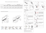
Page is loading ...

V230504
ACCESS & INDUSTRIAL CONTROL
X7 X2 X1 X2 X2
X1 X1 X1X1X1
- 1 -
VR2
J1
J1
VR2
VR1
VR1
N.O
N.O
N.C
N.C
V+
V+
V-
V-
COM
COM
Relay
Relay
AR-0600M-270 Electromagnetic Lock
Product Information
Electromagnetic Lock Optional Order (Bracket)
Product Specication & Key Features
Power Supply : 12VDC / 24VDC
Current Draw : 560mA/12VDC;280mA/24VDC
Door Monitoring Output: Door Relay Status (N.O/N.C/COM)
Holding Force : 270KG( 600LBS)
Lock Surface Temperature: ≦ ambient temperature ± 20°C
Operating Temperature : -10°C ~ +55°C
Lock Body Dimension (mm) : 47(H) x 251(W) x 25(D)
Armature Plate Dimension (mm) :40(H) x 185(W) x 15(D)
Material : Alluminum Alloy 6063-T5
Holding force increased by 10%,250Kgs---->270Kgs
Lock Body mounting plate (thickened from 6mm to 8mm) and xing screw (increased from M4 to M5), lock strength is greatly
improved
The overall size of lock body remain the same, support both old and new installation.
Registered patent for Anti Falling Design, prevent lock to fall down when screw is loosening, enhance safety.
(Patent no. :USA 16/828.910 , Taiwan I679336 , EP 20168852.0-1005 , China 202010227686.3)
Registered patent for Anti Residual Magnetism design, anti-residual magnetism part located the edge of electromagnet, more
durable than conventional anti-residual magnetism design that easily oxidized dust on the armature plat(Patent no.: Taiwan
M597321 / EP20168849.6 / China 202010170047.8)
Registered patent for Strong Lock Design, newly designed strong lock base and eliminating the unnecessary screws.(Patent no.
:USA 16/828.931 ,Taiwan I679336, EP 20168852.4, China 202010227687.8)
Entire lock body comply with UL94V0 standard (re resistance and self-extinguishing characteristic)
Content
Fixing Screw
4mm*25mm
Rubber Armature
Screw M8*20mm
Guide Pin
Hexagon Allen
Wrench(M4)
Hexagon Allen
Wrench(M5)
Rubber Washer Flat Washer
Sexnut Bolt
Secure Nut
Aluminum Pipe
2Installation Diagram for
Magnetic Lock Sticker
1Accessories & Tools
Wire
Application
Wire Description
DSS
(Door Sensor
Status)
N.O. (N.O) DC 24V 1 Amp
COM (COM) DC 24V 1 Amp
N.C. (N.C) DC 24V 1 Amp
Power V+ DC 12V or 24V
V- DC 0V
AR-0600M-270
N.O.
COM
N.C.
V+
V-
AR-MA-46190
Specication Key Features
AR-0600M-270 AR-0600MZL-M5 AR-0600M-U AR-721RB
LZ Bracket U Bracket Relay
Armature Plate (MA) Bracket
(*Purchase Recommendation) (with Time Delay)
DC 12V: Factory Default Value
DC 24V: move J1 as shown
Wiring Table
Wiring Diagram & Installation Manual
Voltage Adjustment
1234
AR-600M / 600M-270

V230504
ACCESS & INDUSTRIAL CONTROL
25.8
40
16
16
Ø9.50
82.5 82.5
250
185.5
185.5
27.2
51.4
43.4
8
250
38 24 50 50 60
7.5 7.5
AR-0600M-270 Electromagnetic Lock
Magnetic Lock wire to Access Controller Magnetic Lock wire to External Relay Output
(With time delay)
EXIT
N.O.
COM
N.C.
V+
V-
COM
N.C.
N.O.
CTL
12V
PB
GND
Power
DC12V-24V
Relay
AR-721RB
Push Button
Magnetic
Lock
1
2
3
4
5
6
7
8
COM
N.C.
SENSOR
12V
GND
N.O.
COM
N.C.
V+
V-
Controller
Magnetic
Lock
Power
DC12V-24V
Unit (mm)
Dimension and Diagram
Installation Manual
Lock Body Top view
Lock Body Front view Lock Body Side view
Armature Plate Side view
Armature Plate Top view
Armature Plate Front view
AR-0600M-270
AR-0600M-270

V230504
ACCESS & INDUSTRIAL CONTROL
- 2 -
AR-0600M-270 Electromagnetic Lock
For Lock Body
For Armature Plate
Installation Diagram Template
Instructions for use:
[For lock body]
Place the template into proper position of the door and frame. Mark the hole
positions and drill the hole.
[For Armature Plate] Installation Diagram Template for armature plate is
divided into :
Part 1.Standard Installation: holes position (marked with blue circles), holes can
be drilled as required.
Part 2. With Armature Plate AR- MA-46190: holes position can follow installation
diagram template, holes can be drilled as required.

V230504
ACCESS & INDUSTRIAL CONTROL
- 3 -
AR-0600M-270 Electromagnetic Lock
Installation Instruction
Armature Plate
Fix sexnut bolt, aluminum pipe, at washer, rubber washer,
and rubber armature screw by sequence based on the picture
above. Last, lightly fasten the guide pin to secure the armature
plate
Stick the Installation Template sticker into the hole drilling
position and mark the hole drilling position for armature
plate
Separate the Installation Template Sticker into two
parts, take the armature plate's part and place it into
the door position
Drill the hole based on the hole position on the sticker,
after it is done, remove the sticker
Armature Installation Side View
1 2
53
6
Separate the Installation Template Sticker
Install armature plate
Mark hole drilling position
Finished installation
Hole drilling
Suggestion for door
hole is 10mm
Sexnut Bolt Aluminum
Pipe
Flat Washer
Armature Plate
Rubber Washer Rubber Armature
Screw M8*20mm
For Lock Body For Armature Plate
Armature plate xed to door, the installation is nished.
※Remarks: Rubber washer can make small adjustment
and movement for the armature plate, but still tightly
secured armature plate and lock body.

V230504
ACCESS & INDUSTRIAL CONTROL
- 3 -
AR-0600M-270 Electromagnetic Lock
Installation Instruction
Armature Plate with Bracket
Fix rubber washer, armature plate as well as
rubber armature screw by sequence. Last, lightly
fasten the guide pin to secure the armature plate.
Stick the Installation Template sticker into
the hole drilling position and mark the
hole drilling position for armature plate
Fix the screw and install AR-MA-46190 bracket
as a base of armature plate for higher security.
Separate the Installation Template Sticker
into two parts, take the armature plate's
part and place it into the door position
Drill the hole based on the hole position
on the sticker, after it is done, remove the
sticker
Armature Plate Installation Reference
1
4
2
5
3
6
Install AR-MA-46190 bracket
Separate the Installation
Template Sticker
Install the armature plate and
x to the bracket.
Mark hole drilling position
Armature plate xed to bracket,
the installation is nished.
Hole drilling
Suggestion for door
hole is 10mm
AR-MA-46190 Armature Plate
Rubber Washer Rubber Armature
Screw M8*20mm
For Lock Body For Armature Plate
Armature plate xed to bracket, the installation is nished.
※Remarks: Rubber washer can make small adjustment and
movement for the armature plate, but still tightly secured
armature plate and lock body.

V230504
ACCESS & INDUSTRIAL CONTROL
SOYAL
1
1
1
1
2
3
2
2
2
2
3
- 4 -
SOYAL
SOYAL
SOYAL
AR-0600M-270 Electromagnetic Lock
Installation Instruction
4
7
1
6
8
2
5
3
Remove the Mounting Plate
from the lock body
Install lock body on the Mounting Plate
Draw positioning line of lock
body
Wiring & Voltage Adjustment
Complete the assemble of The Mounting Plate
on the Lock body
Mark hole drilling position
Mounting Plate x to door
frame
Hole drilling
Stick the Installation Template sticker into
the hole drilling position and mark the
hole drilling position for lock body
Drill the hole based on the hole position
on the sticker, after it is done, remove the
sticker
Put the lock body into the door frame, compare
it to the armature plate position (the position
should be considering armature plate position,
so when door is closed, lock is properly locked).
Draw the lock body position for marking.
Step 1: Patented Anti-Falling Design, with at shrapnel on both sides of
the magnetic lock, starting from left or right, tilt the lock to either left or
right and buckle the at shrapnel
Step 2: Continue to buckle the other side, so that the magnetic lock
body and the Mounting Plate are tightly buckled
Use the Hexagon Allen Wrench to x the magnetic lock on
the Mounting Plate.
Step 1: Use provided Hexagon Allen Wrench to
loosen the screws on the lock body to the state
where the Mounting Plate can be removed (do not
remove all)
Step 2: Move the Mounting Plate to the left or right
by approx.1mm
Step 3: Remove the at shrapnel from the Mounting
Plate and pull upward
Step 1: Loose the screw to open Cover
Part
Step 2: Wire cable and bring the cable
out to the hole and adjust voltage if
necessary
Step 3: Fix the Cover Part back with the
screw
Step 1: Fix the middle hole on the door frame
position with Fixing Screw 4mm*25mm.
At this time, you can adjust the installation
position.
Step 2: Fix the remaining holes with Fixing
Screw 4mm*25mm to the door frame to nish
Mounting Plate installation.

V230504
ACCESS & INDUSTRIAL CONTROL
- 5 -
AR-0600M-270 Electromagnetic Lock
Narrow Door Installation (Inswing Door)
Narrow Door Installation (Outswing Door)
Frameless Glass Door
Door Frame
L Bracket
Z Bracket
L Bracket
Lock : AR-0600M-270
Bracket : AR-0600MZL-M5
Lock : AR-0600M-270
Bracket : AR-MA-46190 + AR-0600MZL-M5(L)
Lock : AR-0600M-270
Bracket :AR-MA-46190+ AR-0600M-U
Door Frame
Door Frame
Installation with Bracket
U Bracket
Electromagnetic
Lock Electromagnetic Lock
Electromagnetic Lock
Electromagnetic Lock
Electromagnetic
Lock
Electromagnetic
Lock
Armature Plate
Bracket(MA Bracket)
Armature Plate
Bracket(MA Bracket)
Armature plate
L Bracket
Z Bracket
Armature plate
Armature Plate Bracket
(MA Bracket)
L Bracket
Armature Plate Bracket(MA Bracket)
Armature plate
U Bracket
/


