Page is loading ...

202011 Ver:1.0
Shenzhen Kstar New Energy Company Limited
Add:Kstar Industrial Park, Guangming Hi-Tech Park,
shenzhen ,P.R.CHINA
Tel:0755-21389008 Fax:0755-21389008
Web:www.kstar.com
INSTALLATION, OPERATION &
MAINTENANCE MANUAL
KSTAR BluE-H5/H3
ENERGY STORAGE SYSTEM

This manual is under the copyright of Shenzhen Kstar Science and
Technology Co., Ltd, with all rights reserved. Please keep the manual
properly and operate in strict accordance with all safety and operating
instructions in this manual. Please do not operate the system before
reading through the manual.
Copyright Statement
Stock code:002518

07
65
66
65
Routine Maintenance
7.1 Alarm code
7.2 Error code
0867
Fault diagnosis and solutions
11 76
Quality Assurance
0970
Machine Parameters
10 75
Routine Maintenance
12 77
Contact Informaition
03
02
01
04
05
Installation
01
04
06
07
08
11
13
14
16
27
30
31
31
01
14
30
32
34
32
62
62
System Operation
1.1 System Introduction
1.3 Safety Introduction
1.4 Battery Safety Datasheet
1.5 General Precautions
1.6 Parts List
1.7 System Appearance
1.8 Liability Limitation
2.1 Installation Site and Environment
2.2 Installation
2.3 External CT connection
3.1 Switch On
3.2 Switch Off
3.3 Emergency Procedure
EMS Introduction And Set UP
4.1 Function Description
4.2 Display and Setting
Wireless Router Connection
CONTENTS
5.1 Download APP
5.2 Connect Wi-Fi Datalogger 62
4.3 Setting
4.4 Inquiry
4.5 Statistics
38
58
59
06
63
64
63
Create Account And Add Datalogger
6.1 Create Account
6.2 Add Datalogger
4.6 Restart 61
Introduction
27
2.4 DRED port connections(optional)
28
2.5 Single Line Diagram
03
1.2 Operation Modes

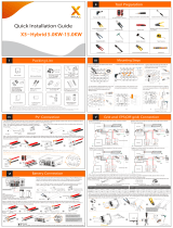
Figure1 DC-coupled Storage System – Scheme
Figure 3 Hybrid-coupled Storage System – Scheme
Introduction
01
Kstar BluE-H5 (incl.BluE-PACK10.2 and BluE-S 5000D)/BluE-H3 (incl. BluE-PACK5.1
and BluE-S 3680D) can be applied in DC-coupled systems (mostly new installation),
AC-coupled systems (mostly retrofit) and Hybrid-coupled systems (mostly retrofit, and
PV capacity-increase), as the following schemes show:
User Manual User Manual
01 www.kstar.com 02
www.kstar.com
GridGrid Meter
Backup Loads
BluE-H5/H3
LAN
Monitoring
Device
PV
Normal Loads
CT
Figure 2 AC-coupled Storage System – Scheme
CAUTION:
If CT test pass but inverter still can't achieve export power
(power is not controllable or always 0 power output).
Please check installation location of the CT.
1.1 System Introduction
BluE H3-5
BluE H3-10
BluE H5-10
BluE H5-20
BluE-S 3680D
BluE-S 3680D
BluE-S 5000D
BluE-S 5000D
BluE-PACK5.1
BluE-PACK10.2
BluE-PACK10.2
BluE-PACK20.4
Inverter ESS
Solution
Configuration
PV
PV
Monitoring
Device
LAN
BluE-H5/H3
PV Inverter Grid Meter Grid
Backup Loads
Normal Loads
CT
GridGrid Meter
Backup Loads
BluE-H5/H3
LAN
PV Inverter
PV
Monitoring
Device
Normal Loads
CT

1.2 Operation Modes:
There are three basic modes that end users can choose via inverter screen/APP.
User Manual User Manual
03 www.kstar.com 04
www.kstar.com
• BAT PRIORITY: Under this mode, the battery is only used as a backup power
supply when the grid fails and as long as the grid works, the batteries won’t be used
to power the loads. The battery will get charged with the power generated by the PV
system or from the grid.
• PEAK SHIFT: This mode is designed for time-use mode customer. The customer is
able to set up the charging/discharging time & power via inverter screen or APP.
• SELF CONSUME: The energy generated by the solar panels will be used in the
following order: Feed the home loads; Charge the battery and then, feed into the
grid.When the sun is off, the load will be supported by battery to enhance self
consumption. If the power supply from the batteries is not sufficient, the grid will
support the load demand.
$
TIME
Electricity Price
1.3.2 Operator Requirements
The operators should get a professional qualification, or be trained.
The operators should be familiar with the whole storage system, including
compositions and working principles of the system.
The operators should be familiar with the Product Instruction.
While maintaining, the maintainer is not allowed to operate any equipment until all the
equipment has been turned off and fully discharged.
The warning signs contain important information for the system to operate safely, and
it is strictly prohibited to torn or damage them. Ensure that the warning signs are
always well-functioned and correct placed. The signs must be replaced immediately
when damaged.
1.3.3 Protection of Warning Sign
1.3.1 Manual Keeping
This manual contains important information about operating the system. Before
operating, please read it very carefully.
The system should be operated in strict accordance with the instructions in the
manual,otherwise it can cause damages or loss to equipment, personnel and property.
This manual should be kept carefully for maintenance and reparation.
1.3 Safety Introduction

1.4.1 Hazard Information
1.3.4.Setting of Warning Sign for Safety
This sign indicates a hazardous situation which, if not avoided,
could result in death or serious injury!
This sign shows danger of hot surface!
Refer to the operating instructions.
The Storion BluE-H5/H3 must not be touched or put into service until
5 minutes after it has been switched off or disconnected to prevent
an electric shock or injury.
During instruction, maintenance and repair, follow the instructions below to prevent
non-specialist personnel from causing misuse or accident:
Obvious signs should be placed at front switch and rear-level switch to prevent
accidents caused by false switching.
Warning signs or tapes should be set near operating areas.
The system must be reinstalled after maintenance or operation.
To ensure the electrical parameters to match requirements, related measuring
equipment are required when the system is being connected or tested.
Ensure that the connection and use matched specification to prevent electric arcs or
shocks.
It is very likely that moisture may cause damages to the system. Repair or maintaining
activities in wet weather should be avoided or limited.
The battery system is part of the energy storage system which stores life-threatening high
voltage even when the DC side is switched off. Touching the battery outlets is strictly
prohibited. The inverter can keep a life-threatening voltage even after disconnecting it
from the DC and / or AC side. Therefore, for safety reasons, it must be tested with a
properly calibrated voltage tester before an installer works on the equipment.
Exempt from classification according to Australian WHS regulations.
Classification of the hazardous chemical
Other hazards
This product is a Lithium Iron Phosphate Battery with certified compliance under the
UN Recommendations on Transport of Dangerous Goods, Manual of Tests and
Criteria, Part III, subsection 38.3. For the battery cell, chemical materials are stored in
a hermetically sealed metal case, designed to withstand temperatures and pressures
encountered during normal use. As a result, during normal use, there is no physical
danger of ignition or explosion and chemical danger of hazardous materials' leakage.
However, if the product is exposed to a fire, added mechanical shocks, decomposed,
added electric stress by misuse, the gas release vent will be operated. The battery cell
case will be breached at the extreme. Hazardous materials may be released.
Moreover, if heated strongly by the surrounding fire, acrid or harmful fume may be
emitted.
5min
1.3.5 Measuring Equipment
1.3.6 Moisture Protection
1.3.7 Operation After Power Failure
05 www.kstar.com 06
www.kstar.com
1.4 Battery Safety Datasheet
User Manual User Manual
1.4.2 Safety Datasheet
For detailed information please refer to the provided battery safety datasheet.

CAUTION:
Risk of injury through lifting or dropping the system. The inverter and battery are
heavy. There is risk of injury if the inverter or battery is lifted incorrectly or dropped
during transport or when attaching to or removing from the wall.
Lifting and transporting the inverter and battery must be carried out by more
than 2 people.
WARNING
Do not install the system in any environment of temperature below -10°C or over
50°C and in which humidity is over 90%.
Do not touch the system with wet hands.
Do not put any heavy objects on top of the system.
Do not damage the system with sharp objects.
Do not install or operate the system in potentially explosive atmospheres or
areas of high humidity.
Do not mount the inverter and the battery pack in areas containing highly
flammable materials or gases.
If moisture has penetrated the system (e.g. due to a damaged enclosure), do not
install or operate the system.
Do not move the system when it is already connected with battery modules.
Secure the system to prevent tipping with restraining straps in your vehicle.
A certified ABC fire extinguisher with minimum capacity of 2kg must be carried
along when transporting.
It is totally prohibited to smoke in the vehicle as well as close to the vehicle when
loading and unloading.
For the exchange of a battery module, please request for new hazardous goods
packaging if needed, pack it and let it be picked up by the suppliers.
In case of contact with electrolyte, rinse the affected areas immediately with
water and consult a doctor without delay.
4xM5*12
2xMC4 1xUser Manual
1xCollector
1xCT Connector
BluE-S 5000D/BluE-S 3680D
Risk of chemical burns from electrolyte or toxic gases. During standard operation, no
electrolyte shall leak from the battery pack and no toxic gases shall form. Despite
careful construction, if the Battery Pack is damaged or a fault occurs, it is possible that
electrolyte may be leaked or toxic gases formed.
Check the following parts list to ensure it is complete.
Kstar delivers a total system separately on site to client, this consists of:
07 www.kstar.com 08
www.kstar.com
The transportation of Kstar BluE-H5/H3 must be made by the manufacturer or
an instructed personal. These instructions shall be recorded and repeated.
1xCT and
com cable
DANGER
Do not touch uninsulated cable ends.
Do not touch the DC conductors.
Do not open the inverter and battery.
Do not wipe the system with damp cloth.
Have the system installed and commissioned by qualified people with the
appropriate skills only.
Prior to performing any work on the inverter or the battery pack, disconnect the
inverter from all voltage sources as described in this document.
Danger to life due to high voltages of the PV array, battery and electric shock. When
exposed to sunlight, the PV array generates dangerous DC voltage which will be
present in the DC conductors and the live components of the inverter. Touching the DC
conductors or the live components can lead to lethal electric shocks. If you disconnect
the DC connectors from the system under load, an electric arc may occur leading to
electric shock and burns.
1.5 General Precautions
1.6 Parts List
User Manual User Manual
2xAC Collector
1x Mounting Panel
2xφ8*60
202011 Ver:1 .0
INSTALLATION, OPERATION &
MAINTENANCE MANUAL
KSTAR B luE-H 5/H3
ENERGY STORAGE SYSTEM

12xφ8*60
12xM6 Gasket 1x Battery Communication Cable
4xPower Cable
(2 black, 2 red)
6x M5*123x Mounting Panel
16xφ8*60
16x M6 Gasket 1xBattery Communication Cable
6x Power Cable
(3 black, 3 red)
8xM5*124xMounting Panel
09 www.kstar.com 10
www.kstar.com
BluE-PACK15.3 (includ three pieces BluE-PACK5.1)
BluE-PACK20.4 (includ four pieces BluE-PACK5.1)
8xφ8*60
8xM6 Gasket 1x Battery Communication Cable
2xPower Cable(1 black, 1 red)
4xM5*122xMounting Panel
BluE-PACK10.2 (includ two pieces BluE-PACK5.1)
4xφ8*60 4xM6 Gasket2xM5*12
1x Mounting Panel
BluE-PACK5.1
User Manual User Manual

1.7.1 Cable Box Part
Figure 5 Inverter without Cable Box Covers– Front View
1
2
3
4
5
Hybrid Inverter BluE-S 5000D/3680D
EMS Display Screen
Cable Box (connected to Inverter)
BluE-PACK5.1 (Battery 1)
BluE-PACK5.1 (Battery 2, if configured)
Object
Figure 4 BluE-H5/H3 Delivery Scope
Figure 6 Cable Box Part without Covers – Front View
11 www.kstar.com 12www.kstar.com
1
2
3
5
4
Descripition
1
2
3
Battery circuit breaker
DC isolation switch
Output terminal block(BACK UP/ON GRID)
Object Descripition
1.7 System Appearance
User Manual User Manual
2
1
3

Installation
PV1, PV2
1
Any product damage or property loss caused by the following conditions, Kstar does
not assume any direct or indirect liability.
2.1.1 General
NOTE:
Please be cautious unpacking the battery, otherwise components could be damaged.
This Manual introduces the basic steps to install and set up Kstar BluE-H5/H3.
This BluE-H5/H3 energy storage system is outdoor version and can be installed in an
outdoor or an indoor location.
When BluE-H5/H3 systems are installed in a room, BluE-H5/H3 must not be hampered by
the structure of the building, the furnishings and equipment of the room.
The Storion BluE-H5/H3 is naturally ventilated. The location should therefore be clean, dry
and adequately ventilated. The mounting location must allow free access to the unit for
installation and maintenance purposes, and the system panels must not be blocked.
The following locations are not allowed for installation:
The BluE-H5/H3 shall not be installed :
(a) in restricted locations as defined for panels in AS / NZS 3000;
(b) within 600mm of any heat source, such as hot water unit, gas heater, air conditioning
unit or any other appliance.
(c) within 600mm of any exit;
(d) within 600mm of any window or ventilation opening;
(e) within 900mm of access to 240Vac connections;
(f) within 600mm of side of other device.
2.1.2 Restricted Locations
habitable rooms;
ceiling cavities or wall cavities;
on roofs that are not specifically considered suitable;
access / exit areas or under stairs / access walkways;
where the freezing point can be reached, such as garages, carports or other places as
well as wet rooms (environmental category 2);
locations with humidity and condensation over 90%;
places where salty and humid air can penetrate;
seismic areas - additional security measures are required;
Sites with altitude below 2000m;
places with an explosive atmosphere;
locations with direct sunlight or a large change in the ambient temperature;
places with flammable materials or gases or an explosive atmosphere.
Product modified, design changed or parts replaced without authorization;Kstar
Changes, repair attempts and erasing of series number or seals by non Kstar
technician;
System design and installation are not in compliance with standards and regulations;
Fail to comply with the local safety regulations (VDE for DE, SAA for AU);
Transport damage (including painting scratch caused by rubbing inside packaging
during shipping). A claim should be made directly to shipping or insurance company
in this case as soon as the container/packaging is unloaded and such damage is
identified;
Fail to follow any/all of the user manual, the installation guide and the maintenance
regulations;
Improper use or misuse of the device;
Insufficient ventilation of the device;
The maintenance procedures relating to the product have not been followed to an
acceptable standard;
Force majeure (violent or stormy weather, lightning, overvoltage, fire etc.);
Damages caused by any external factors.
02
GRID
13 www.kstar.com 14
www.kstar.com
2
BACKUP
3DRM4
COM
5CT/METER
6
INV
7BAT+,BAT-
8
1.8 Liability Limitation
2.1 Installation Site and Environment
User Manual User Manual
DVC C DVC C
DVC C DVC A
DVC A DVC A
DVC B/C DVC C
Description Description
Object Object
DVC class DVC class
Figure 7 Cable Box Part without Covers
2
3
1
BACK UP
ON GRID
PV1+
PV1-
PV2+
PV2-
DRM
COM
CT/METER
INV BAT+ BAT-
78
4
5
6
8
9
RJ45
9DVC C

2.1.3 Barrier to Habitable Rooms
A BluE-H5/H3 installed in any corridor, hallway, lobby or the like and leading to an
emergency exit shall ensure sufficient clearance for safe egress of at least 1 meter.
The BluE-H5/H3 must also not be installed in potentially explosive atmospheres for gas
cylinders that are heavier than air gases and have a vent clamp in accordance with AS /
NZS 3000.
To protect against the spread of fire in living spaces where the BluE-H5/H3 is mounted or
on surfaces of a wall or structure in living spaces with a BluE-H5/H3 on the other side, the
wall or structure shall have a suitable non-combustible barrier. If the mounting surface
itself is not made of a suitable non-combustible material, a non-combustible barrier can be
placed between the BluE-H5/H3 and the surface of a wall or structure.
If the BluE-H5/H3 is mounted at a wall or at a distance of 300mm from the wall or the
structure separating it from the habitable space, the distances to other structures or
objects must be increased. The following distances must remain free :
(i) 600 mm beside the BluE-H5/H3;
(ii) 500 mm above the BluE-H5/H3;
(iii) 600 mm before the BluE-H5/H3.
If the distance between the BluE-H5/H3 and the ceiling or any object above the system is
less than 500mm, the ceiling or structural surface above the system must be made of
noncombustible material within a radius of 600mm around the system.
The BluE-H5/H3 must be mounted to ensure the highest point is not more than 2.2m
above the ground or the platform.
Step 1 Remove the battery and inverter from the packaging box.
Figure 9 Unpacking the
inverter and battery
15 www.kstar.com 16
www.kstar.com
≥600mm≥600mm
≥500mm
≥600mm
Top----------- 500mm
Front--------- 600mm
Laterals------600mm
Figure 8 Limited Distance of Installation to Neighboring Objects
Step 2 Assemble the battery mounting panel on the battery.
Figure 10 Assemble Battery Mounting Panel
M5*12 Screws
2.2.1 Battery Installation
2.2 Installation
User Manual User Manual
Step 3 Position the battery parallell to the wall and use a Φ8mm drill to drill holes at a
depth of about 70mm in the wall for sub sequent fix ation of the mounting plates.
Debris Baffle, drill φ8,
depth about 70 mm
Figure 11 Battery Installation -
Drill Holes

Hang the inverter onto the mounting panels, adjust the entire system and
ensure that the battery and the inverter have been securely hung onto the panels and
brackets.
Step 4
Remove the debris baffle and secure the battery to the wall with screws and gaskets.
NOTE:
The type B RCD must be installed on the backup port of the system.In additon, the
installation of inverter must fulfill AS/NZS 3000,AS/NZS 4777.1 and AS/NZS 5033.
Figure 12 Battery Installation – Mounting on the Wall
17 www.kstar.com 18
www.kstar.com
ST6.3*50
Gasket
To assemble the second (and all other) battery, repeat steps 6 and 7,
respectively.
Figure 13 Battery Installation –
Second Battery Installation
2.2.2 Inverter Installation
Step 7
Inverter Installation.
Figure 14 Inverter Installation
Figure 15 Inverter Installation on the Wall
Step 6
Step 5
User Manual User Manual
the internal N line of converter is connected to grid neutral via internal relays, when
in stand-alone mode.

Please make AC cables on site.
Please follow the AC cable requirements below.
19 www.kstar.com 20
www.kstar.com
Step 8-1
Step 8
User Manual User Manual
WARNING:
There are"L" "N'' '' '' symbols marked inside the connector, the Line wire of
grid must be connected to "L" terminal; the Neutral wireof grid must be
connected to "N" terminal; the Earth of grid must be connected to '' ''
For all AC connections, 4-10mm² 105 XJ cable is required to be used. Please make
sure the resistance of cable is lower than 1 ohm. If the wire is longer than 20m, it's
recommended to use 10mm² cable.
Object Description Value
12mm to 18mm
4mm² to 10mm²
approx.13mm
approx.53mm
External diameter
Copper conductor cross-section
Stripping length of the insulated conductors
Stripping length of the outer sheath of the AC cable
A
B
C
D
The PE conductor must be 10mm longer than the L and N conductors
b. Insert the conductor into the suitable ferrule acc. to DIN 46228-4 and crimp the contact.
c. Unscrew the swivel nut from the threaded sleeve and thread the swivel nut and threaded
sleeve over the AC cable.
d. Insert the crimped conductors L, N and PE into the corresponding terminals and tighten the
screw with a hex key wrench screwdriver(size:2.5, 1.2-2.0N.m). Ensure that all conductors are
securely in place in the screw terminals on the bush insert.
e. Screw the swivel nut onto the threaded sleeve. This seals the AC connector and provides
strain relief for the AC cable. When doing so, hold the bush insert firmly by the locking cap.
This ensures that the swivel nut can be screwed firmly onto the threaded sleeve.
f. Assembly the plug shell ,adapter as below picture, Push the adapter and Shell by hand until
a “Click” is heard or felt.
g. Plug the AC connector into the jack for the AC connection by hand until a “Click” is heard
or felt.
b
c
d
e
f
A
B
DC
U
O
W

NOTE:
The communication cable is in type B, see Figure 18. Leave the power cables
and communication cables hanging on outside. Leave the device aside.
Take out the communication cable set provided in the accessory parts of one
BluE-H5/H3-BAT, cut off one end and crimp a new RJ45 connector. If there are two
batteries,you only need to remake one of battery communication cable on site.
Figure 18 Network Cable Type B
21 www.kstar.com 22
www.kstar.com
Step 9
1
2
3
4
5
6
7
8
Or/W
Or
G/W
BI
BI/W
G
Br/W
Br
Or/W
Or
G/W
BI
BI/W
G
Br/W
Br
RJ45 Connector RJ45 Connector
1
2
3
4
5
6
7
8
User Manual User Manual
Step 8-2 Connect the Backup and Grid cables in advance according to the connector
mode, and connect them to the Backup and Grid board connectors in turn.
(8) Use tool to clamp the AC wiring terminal and wire rod; screw the nut, but do not
tighten it. Make sure that the cable is free to pass through the waterproof components.
Once the terminal is connected to the right site of the inverter, tighten the nut.
(9) Connect the AC wiring terminal to the corresponding hole site of the inverter and
lock it with a screw driver or electric screw driver (suggestion: stem diameters and
torsion of screwdriver or electric screwdriver should be 4mm and 8~12kg-f.cm
respectively)
(10) Tighten the nut.
(11) Circuit breaker parameters are recommended:
Back-up 32A/400Vac 6KA
On-grid 40A/400Vac 6KA
Figure 16
Figure 17 Cable Box Bottom View, Wiring Connectors
BACK UP
ON GRID
PV1+
PV1-
PV2+
PV2-
DRM
COM
CT/ME TE R

Connect the BAT communication cable of the cable box from Step 13 to the
topmost battery at the right side. Then use the communication cable supplied with the
batteries to connect the batteries to each other via the respective connectors on the
left side. After you have connected all the modules together, close all covers (if you
want to connect further battery modules, you must mount them before closing).
Step10
Connect the power cables of the bottom battery from Step 4 to the side
terminals of the top battery. Make sure that red connects to red and black connects to
black.
Figure 19 Wiring the Communication Cable
23 www.kstar.com 24
www.kstar.com
Step11
Figure 20 Wiring the Battry
Power Cable
Close the battery covers and connect the PV-MC4 connectors to the system
(connection on both sides). Also, connect all AC cables, the meter communications
cable METER, and the Ethernet cable LAN. Then close the cable box cover.
The installation is now complete.
Step13
Close the lid and tighten the screw.
Step12
Figure 21
User Manual User Manual
4*MC4
Figure 22 PV Wiring
BACK UP
ON GRID
PV1+
PV1-
PV2+
PV2-
DRM
COM
CT/ME TE R

NOTE:
The DIP setting is only changed on the last battery.
If you connect more than 2 battery modules to the system, please only install the
additional batteries 3-4 on the side of the system. You can connect up to 4 batteries, 2
each mounted on top of each other, to the BluE-H5/H3.
To do this, carry out the individual installation steps as for the first two batteries,
including the DIP setting on the last module.
Open the front cover of the last battery and remove the DIP cover. Now set
the DIP switch 2 to "on" mode and close the cover again.
Step14
Figure 24 Increase the Battery Modules
Figure 23 DIP Operation
25 www.kstar.com 26
www.kstar.com
NOTE:
Recommended AC circuit breaker rating is 32A.
ON
1 2 3 4 5
DIP switch setting
address
#2
DIP switch position
#4
1
ON
OFF
#3
OFF OFF
2
OFF
ON
OFF OFF
3 ON ON
OFF OFF
4 OFF OFF
ON OFF
5 ON OFF
ON OFF
6
OFF
ON
ON OFF
7
ON
ON
ON OFF
8 OFF OFF OFF ON
When PACKs are used in parallel, the address can be distinguished by setting the
address on the BMS DIP switch. It is necessary to avoid setting the address to the
same. For the definition of the BMS DIP switch, refer to the following table.
User Manual User Manual
STATEMENT:
The method of anti-islanding protection is Method(c)
NOTE:
The address of the battery pack connected to the inverter is 1, and the others are
dialed in the order of 2-8.
NOTE:
It is necessary to disconnect the power line, communication line and communication
line between battery pack and inverter to manually sleep all battery packs.
ON
1 2 3 4 5
#1
BAT
BAT
DIP Switch

27 www.kstar.com 28
www.kstar.com
The electricity meter should be mounted and connected at the grid transition point
(feed-in point) so that it can measure the grid reference and feed-in power.
1. Loosen the nut, and untangle the single-aperture sealing ring.
2. Install the waterproof component and screw on the waterproof sheath nut.
3. Open the external CT wiring port, the arrow points to the direction of the power grid,
put the wire into the external CT card slot, and buckle the buckle.
NOTE: External CT should be placed near the power grid.
Power grid
line L
PV Panels
PV Switch
DC
DC
AC
PV1
PV2 Grid Switch
Back up
Switch
Grid Meter Grid
Router
Battery
Switch
Norma l Load
BACKUP Lo ad
5kW Hybrid Inverter
BluE-S 5000D
DSP
EMS
CT
The single line diagrams of DC-, AC- and Hybrid-coupled sysyem are as below:
2.5 Single Line Diagram
BluE-PACK
BluE-PACK
BluE-PACK
BluE-PACK
Figure 25
User Manual User Manual
Figure 27 DC-coupled system
Pin Pin
1DRM 1/5
5RefGen
2DRM 2/6
6Com/DRMO
3DRM 3/7
4DRM 4/8
Description Description
Please follow below figure to assemble DRM connector.
Figure 26 DRM connector
DRED means demand response enable device. The AS/NZS 4777.2:2015 required inverter
need to support demand response mode(DRM). This function is for inverterthat comply with
AS/NZS 4777.2:2015 standard. KSG single phase inverter is fully comply with all DRM. A 6P
terminal is used for DRM connection.
Pin Pin
1CT positive electrode
4
2CT negative pole
3
NC
NC
Description Description

Step 2: Turn on the external grid switch.
Step 4: Open the outer shell of the cable box. Open the battery switch cover and turn on
the battery switch on the cable box.
Step 5: Press power button on all the batteries until the indicator lights turn on.
Step 6: Close the battery switch cover and the outer shell of the cable box.
System Operation
03
When turning on the system, it is very important to follow the steps below to prevent
damage to the system.
WARNING: Please check the installation again before turning on the system.
NOTE:
the Backup switch is only used when a backup load is applied.
Step 3: If backup load is applied, turn on the external Backup switch.
Step 1: Turn on the external PV switch.
PV Panels
PV Switch
DC
DC
AC
PV1
PV2 Grid
Switch
Back up
Switch
Grid Meter Grid
Router
Battery
Switch
Normal Load
BACKUP Lo ad
5kW Hybrid
Inverter
BluE-S 5000D
DSP
EMS
CT
PV Meter
AC
DC
PV PanelsPV Inverter
29 www.kstar.com 30
www.kstar.com
BluE-PACK
BluE-PACK
BluE-PACK
BluE-PACK
3.1 Switch On
User Manual User Manual
Figure 29 Hybrid-coupled system
DC
DC
AC
Grid Switch
Back up
Switch
Grid Meter Grid
Router
Battery
Switch
Normal Load
BACKUP Lo ad
5kW Hybrid Inverter
BluE-S 5000D
DSP
EMS
CT
PV Meter
AC
DC
PV PanelsPV Inverter
BluE-PACK
BluE-PACK
BluE-PACK
BluE-PACK
Figure 28 AC-coupled system

Step 1: Press the power button on all the batteries, till the lights turn off.
Step 2: Open cable box outer shell, open the battery switch cover and turn off the battery switch.
Step 3: Turn off the external grid switch.
Step 4: If backup load is applied, turn off the external backup switch.
Step 5: Turn off the external PV switch on the cable box.
Step 6: Close the battery switch cover and the outer shell of cable box.
3.3.3 Fire
Ems Introduction And Set Up
04
3.3.1 Emergency Handling Plan
4.1 Function Description
3.3.2 Hazards
There may be a possible explosion when batteries are heated above 150°C.
When the battery pack is burning, it leaks poisonous gases. Do not approach.
When the BluE-H5/H3 energy storage system appears to be running abnormally, you can turn off
the grid-connected main switch that directly feeding the BESS, and turn off all load switches
within the BESS, turn off the battery switch at the same time. To prevent a potentially fatal
personal injury, if you want to repair or open the machine after the power is switched off,
please measure the voltage at the input terminals with a suitably calibrated voltage tester.
Before working on this equipment, please confirm that there is no grid electric supply to the BESS!
The upper cover plate cannot be opened until the DC-link capacitance inside the battery
modules discharges completely about 15 minutes later.
1.Disconnect the AC breaker.
2.Check the control power supply. If it is OK, return the power supply to find out the reason.
3.Please record every detail related to the fault, so Kstar can analyse and solve the
fault. Any operation of equipment during a fault is strictly forbidden, please contact Kstar as
soon as possible.
4.As battery cells contain a little Oxygen inside and all cells have got explosion-proof valves,
explosion hardly happens.
5.When the indicator light on the battery shows a red fault, check the fault type through the
communication protocol, and contact our after-sales service personnel for advice.
If the battery pack leaks electrolyte, avoid contact with the leaking liquid or gas.
If one is exposed to the leaked substance, immediately perform the actions
described below:
Inhalation: Evacuate the contaminated area, and seek medical attention.
Eye contact: Rinse eyes with running water for 5 minutes, and seek medical
attention.
Contact with skin: Wash the affected area thoroughly with soap and water, and
seek medical attention.
Ingestion: Induce vomiting and seek medical attention.
If a fire breaks out in the place where the battery pack is installed, perform the following
countermeasures:
Fire extinguishing media
During normal operation, no respirator is required. Burning batteries can not be
extinguished with a regular fire extinguisher, this requires special fire extinguishers such
as the Novec 1230, the FM-200 or a dioxin extinguisher. If the fire is not from a battery,
normal ABC fire extinguishers can be used for extinguishing.
Fire -fighting instructions
1. If fire occurs when charging batteries, if it is safe to do so, disconnect the battery pack
circuit breaker to shut off the power to charge.
2. If the battery pack is not on fire yet, extinguish the fire before the battery pack catches
fire.
3. If the battery pack is on fire, do not try to extinguish but evacuate people immediately.
Effective ways to deal with accidents
Battery in dry environment: Place damaged battery into a segregated place and call
local fire department or service engineer.
Battery in wet environment: Stay out of the water and don’ t touch anything if any part
of the battery, inverter, or wiring is submerged.
Do not use a submerged battery again and contact the service engineer.
Figure 30 BluE-H5/H3 EMS Interface
31 www.kstar.com 32
www.kstar.com
A
B
C
D E FH
Figure 31 BluE-PACK Interface
Reset button
Running light
Fault indicator
Capacity indicator
3.2 Switch Off
3.3 Emergency Procedure
User Manual User Manual

A
B
C
D
E
F
H
Indicator LED
Button Function
Name
Object Description
Red: The inverter is in fault.
Grid connection
Return Button: Escape from current
interface or function.
Up button: Move cursor to upside or
increase value.
Down Button: Move cursor to downside or
decrease value.
ENT Button: Confirm the selection.
33 www.kstar.com 34
www.kstar.com
4.2.4 Battery
Interface
BATTERY
VOLT: 42.2V
CURR: 20.2A
CAPACITY: 40Ah
Battery input voltage
Battery current ( +means discharge, -means charge)
Battery Capacity
4.2.3 Bus voltage
Interface
Bus voltage of the system
DC VOLTAGE
BUS: V
4.2.2 PV2 input display interface
Interface
PV2 INPUT
VOLT: 49.8V
CURR: 0.00A
POWER: 0W
PV2 input real-time voltage
PV2 input real-time current
PV2 Input power
4.2.1 PV1 input display interface
Interface
PV1 INPUT
VOLT: 33.8V
CURR:
POWER: 0W
PV1 input real-time voltage
PV1 input real-time current
PV1 input power
Off-grid
LED indicator description
status
ON/
OFF RUN ALM Instructions
●
●
●
●
● ●
● ● ●
dormancy
ALL OFF
Standby
Normal
light Flash
one time
According to battery indicator standby mode
Table 4.1 LED working status indication
Shut down
Normal/Alarm
/Protection
off
Power indicator LED
off off off off off off off off
off
Module low voltage
charge
According to battery indicator
(Power indicator highest LED flashes two)
Overcharge
protection
Temperature,
overcurrent,
failure,
protection
Stop charging
Discharge
Undervoltage
protection
Stop discharging
Failure
Stop charging and
discharging
Alarm
Normal
Alarm
Normal
Alarm
light
light
light
light
light
light
light
light
light
off
light
light
light
off
off
off
light
Flash
three times
off
off
Temperature,
overcurrent,
short circuit,
reverse
connection,
failure
protection
light light light light light light
off off off off off off
light
light
off
According to battery indicator
off
off off off off off off off
off off off off off off
off off off off off off
The maximum
power
LED flashes twice,
and the ALM does
not flash when an
overcharge alarm
occurs
If there is no mains
electricity, the
indicator light turns
to standby
Stop discharging
Flash
three times
Flash
three times
Flash
three
times
Flash
one time Flash
three times
4.2. Display and Setting
User Manual User Manual
0.00A
/