Page is loading ...

IMPORTANT! For safety reasons, the concrete wall must be
capable of supporting the combined weight of the mount
and the display. The manufacturer takes no responsibility for
failure caused by walls of insufficient strength.
(C) Concrete Anchor (x2)
Model: AFM400B
Display Size: 26” to 47”
Maximum Load: 25 kg (55 lbs)
Mounting Pattern: 400 mm x 400 mm (15.7” x 15.7”) max
Tilt Range: up to 10° down
Pan/Swivel Range: up to 180°
Prole: 3.8 cm to 41.5 cm (1.5” to 16.3”)
(A) M8 x 63 Lag Bolt (x2)
(B) Lag Bolt Washer (x2)
(D) M4 x 12 Screw (x4)
(F) M6 x 12 Screw (x4)
(M) S4 Allen Key (x1)
(N) S8 Socket Wrench (x1)
(E)
M4 x 20 Screw (x4)
(G) M6 x 30 Screw (x4)
(I) M8 x 30 Screw (x4)
IMPORTANT! For safety reasons, this mount must be secured
to a wood stud capable of supporting the combined weight
of the mount and display. Do not mount to drywall alone.
Part 1A – Mounting to the Wall (Drywall)
3
4
5
6
SPECIFICATIONS
BOX CONTENTS
HARDWARE KIT
TOOLS REQUIRED
INSTALLATION
(H) M8 x 12 Screw (x4)
Phillips Head Screw Driver
Ratchet or Driver with 13 mm (1/2”) Socket
Electric or Portable Drill
6 mm (1/4”) Drill Bit and Stud Finder for Drywall Installation
10 mm (3/8”) Masonry Bit for Concrete Installation
Level
Mount (x1)
Mount Arm (x2)
Instruction Manual (x1)
Hardware Kit (x1)
Part 1B – Mounting to the Wall (Concrete)
(J) M6 Washer (x4)
Fig. 2
Fig. 3
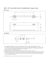
Use a high quality stud finder to locate a stud where you
wish to install your mount. Mark both edges of the stud to
help identify the exact center.
NOTE: You must use the center of
the stud to avoid cracking or splitting
the wood during installation.
Carefully remove the plastic covers
from the mount as shown (see Fig. 1).
Place the mount against the wall and
level it using the integrated bubble
level.
While another person holds the
mount in position, mark two
locations for securing the mount to
the wall (see Fig. 2).
Set the mount aside and drill a 6
mm (1/4”) pilot hole at each marked
location.
Place the mount against the wall
over the drilled holes, making sure
the arrow on the mount points up.
Attach the mount to the wall using
the lag bolts (A) and lag bolt washers (B) provided (see Fig. 3).
Do not over-tighten these bolts and do not release the
mount until all bolts are in place. Ensure that the mount
remains level after all bolts are secured.
1
2
(K) M8 Washer (x4)
(L) Spacer (x8)
Fig. 1
INSTRUCTION MANUAL
FULL-MOTION WALL MOUNT
fits most flat panel TVs
Thank you for choosing the AVS AFM400B. Before beginning installation, please
check all parts are included and undamaged. For any parts enquiries, please
contact AV Supply Group Ltd on (09) 274 9172 or email to info@avsupply.co.nz
PRODUCT CARE: Periodically clean your mount with a dry
cloth. Inspect all screws and hardware at regular intervals
to ensure that no connections have become loose over
time. Re-tighten as needed.
CAUTION: Do not use this product for any purpose not
explicitly specified by AVS. Improper installation may cause
property damage or personal injury. If you do not
understand these directions, or have doubts about the
safety of the installation, contact AVS Customer Service or
call a qualified contractor. AVS is not responsible for damage
or injury caused by incorrect mounting, assembly, or use.
WARNING! This product contains small items that could
be a choking hazard if swallowed. Keep these items away
from young children!
The wall or mounting surface must be capable of
supporting the combined weight of the mount and the
display; if not, the structure must be reinforced.
Locate pipes, wires, or any other hazards in the wall where
you wish to install.
1
2
3
4
5
IMPORTANT SAFETY INSTRUCTIONS
Follow all instructions and recommendations regarding
adequate ventilation and suitable locations for mounting
your display. Consult the owner’s manual for your
particular display for more information.
AV Supply Group (AVS) intend to make this manual
accurate and complete. However, AVS makes no claim that
the information contained herein covers all details,
conditions, or variations. Nor does it provide for every
possible contingency in connection with the installation or
use of this product. The information contained in this
document is subject to change without notice or
obligation of any kind. AVS makes no representation of
warranty, expressed or implied, regarding the information
contained herein. AVS assumes no responsibility for
accuracy, completeness or sufficiency of the information
contained in this document.
7
8
6
Safety gear and proper tools must be used. Failure to do so
can result in injury or damage.

4
5
6
Part 2 – Attaching the Mount Arms to the Display
(continued)
3202297-130416
OPERATION AND ADJUSTMENT
A
B
Fig. 4
Fig. 5
NOTE: This mount comes with a selection of different screw
diameters and lengths to accommodate a wide variety of
display models. Not all of the hardware in the kit will be used. If
you cannot find the appropriate screw size in the kit provided,
consult the manufacturer of your display for more information.
Part 2 – Attaching the Mount Arms to the Display
IMPORTANT! Use extra care during this part of the installation.
If possible, avoid placing your display facedown as it may
damage the viewing surface.
Part 1B – Mounting to the Wall (Concrete)
(continued)
Set the mount aside and drill a 10 mm (3/8”) hole at each
marked location. Remove any excess dust from the holes.
Insert a concrete anchor (C) into
each hole so that it is flush with the
concrete surface (see Fig. 5). A
hammer can be used to lightly tap
the anchors into place if necessary.
NOTE: If the concrete wall is
covered by a layer of plaster or
drywall, the concrete anchor must
pass completely through the layer
to rest flush with the concrete
surface.
Place the mount against the wall
over the drilled holes, making sure
the arrow on the mount points up.
Attach the mount to the wall using
the lag bolts (A) and lag bolt
washers (B) provided (see Fig. 3). Do not over-tighten
these bolts and do not release the mount until all bolts
are in place. Ensure that the mount remains level after all
bolts are secured.
1
2
3
Carefully remove the plastic covers from the mount as
shown (see Fig. 1).
Place the mount against the wall in the desired location
and level it using the integrated bubble level.
While another person holds the mount in place, mark two
locations as shown for securing the mount to the wall(see
Fig. 4).
A
B
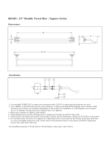
Attach the mount arms to the back of your display using
the screws identified in steps 1 and 2 (see Fig. 6):
If you are using the M4 or M6 screws you will need to use
the M6 washers (J). If you are using the M8 screws you
will need to use the M8 Washers (K).
If you are using the longer screws on a display with a
curved or recessed back, you may also need to use the
spacers (L). Use one spacer or two spacers stacked as
needed. Only use a spacer if necessary.
If the back of your display is flat and the mounting holes
are flush with the surface, you will use the shorter screws
(D, F or H) from the hardware kit.
If the back of your display is curved, has a protrusion, or if the
mounting holes are recessed, you will need to use the longer
screws (E, G or I) and may also need to use the spacers (L).
1
Determine the correct length of screw to use by examining
the back of your display:
2
Determine the correct diameter of screw to use by carefully
trying one of each size (M4, M6 and M8) from the hardware
kit. Do not force any of the screws – if you feel resistance
stop immediately and try a smaller diameter screw.
2
IMPORTANT! The latches must be closed and locked at
all times to prevent the display from being accidentally
knocked from the mount.
1
2
3
To change the tilt angle of your display, have one person
hold the display firmly in place while another person
loosens the tilt screws
using the S4 Allen key
(M) from the hardware
kit (see Fig. 8). Once
loosened, move your
display to the desired
position and then
re-tighten the screws
to lock the angle in
place.
Do not release
the display until both
tilt screws are fully
tightened and never remove the tilt screws.
Swivel adjustments can be made by grasping the display
firmly and moving it to the desired position. Be careful
that fingers or cables do not get pinched when moving
the mount.
Level correction adjustments can be made by simply
rotating the display in
the needed direction. If
it is too difficult to
move the display or if
the display does not
stay in position once
moved, adjust the
tension of the four nuts
located behind the
face plate using the S8
socket wrench (N)
provided in the
hardware kit (see Fig. 9). Adjust all four nuts evenly.
Do not
fully loosen or remove these nuts.
1
With the help of another person, carefully lift your display
and place it on the mount.
Do not release the display
until the mount arms have securely hooked onto the
mount.
Close the safety latch at the
bottom of each arm to prevent
the display from being lifted
from the mount. Each latch will
automatically lock when fully
closed
(see Fig. 7)
.
3
4
Re-attach the plastic covers that we removed in part 1.
Cables can be routed through the channel located on the
bottom of the mount to keep them organized and out of
the way.
Part 3 – Final Assembly
3
Fig. 6
For displays with curved or
recessed backs.
For displays with
at backs.
Fig. 7
Fig. 8
Fig. 9
Part 3 – Final Assembly
(continued)
/