I. SAFETY
PRECAUTIONS
L
hslallation
a
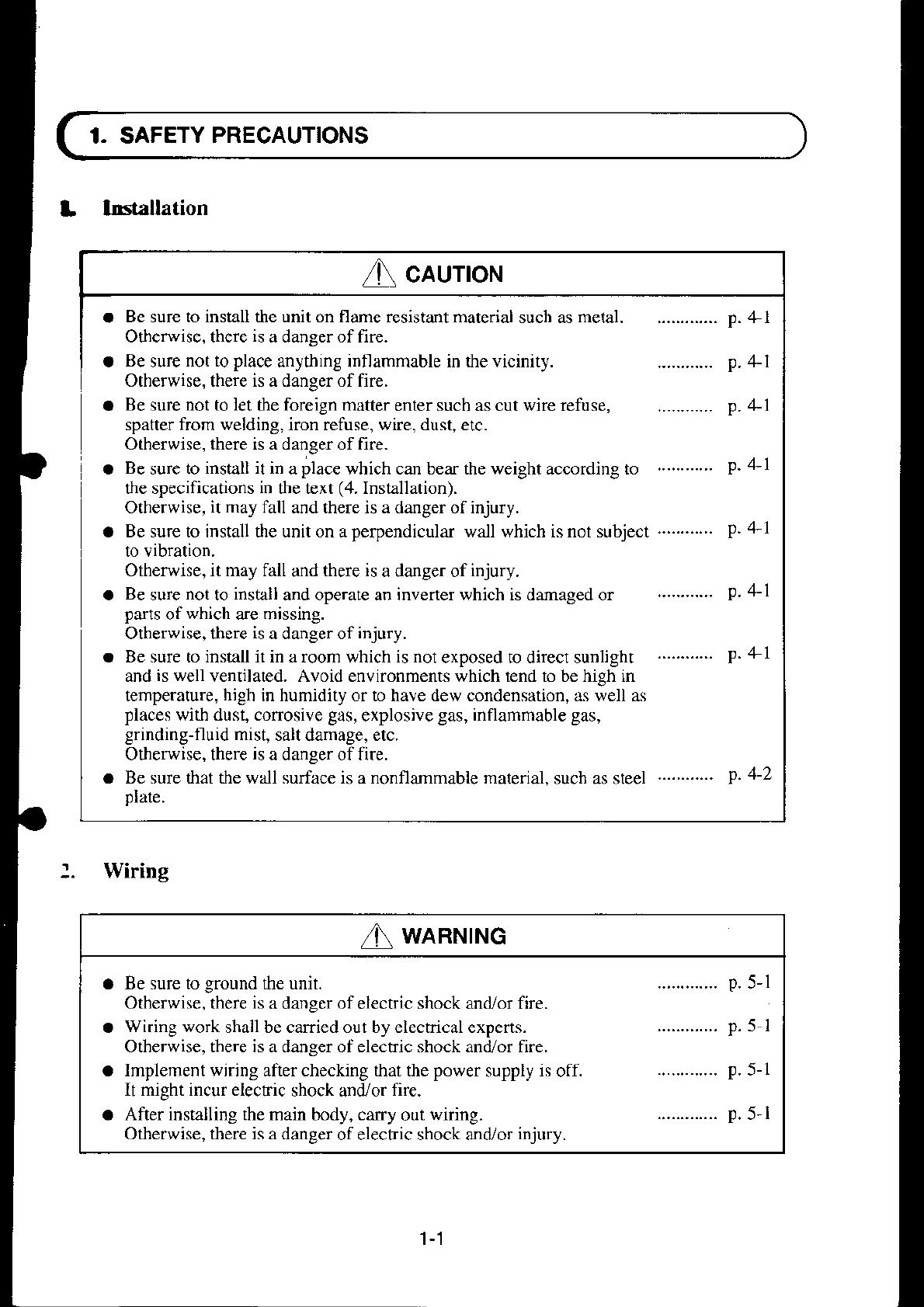
Be sure to install the unit on flame resistant material
such as
metal.
............. D. 4-l
Otherwise. there
is
a danser offire.
a
Be
sure
not to
place
anything inflammable in *re vicinity.
Otherwise. there is a daneer of fire.
o
Be
sure
not to let
the
foreign matter
enter such as cut wire refuse,
spatter from welding, iron refuse, wire, dust, etc.
Otherwise, there is a danger of fire.
a
Be
sure to
install it in
a
place
which can bear the weight according
the specifications
in
tle text
(4.
Installation).
Otherwise,
it may
fall and there is a danger of injury.
a Be sure to install the unit on a
perpendicular
wall which is not subject
Otherwise, it may fall
and
there is
a danger of
injury.
a
Be
sure
not
to
install
and operate an inverter which is damaged or
parts
ofwhich are missing.
Otherwise, there
is
a danger of
injury.
a Be sure to install it in a roorn which is not
exposed to direct sunlight
and
is well
ventilated. Avoid environments which tend to be high in
temperature,
high
in humidity or to have dew condensation, as well as
places
with dust, conosive
gas,
explosive
gas, inflammable gas,
grinding-fluid mist,
salt damage, etc.
Otherwise, there
is
a danger of fire.
a Be sure that the wall surface is
a
nonflarnmable material.
such as steel
Dlate.
Wiring
............
p. +l
............
p. +1
to
...........
P.4-1
............
p.4-l
............
p. +l
............ p.4-1
............ p.4-2
I
caurroH
a
a
WARNTNG
Be sure to
ground
the unit.
Otherwise, there
is
a danger ofelectric shock and/or fire.
Wiring work
shail be caried out by electrical experts.
Otherwise, there is a danger of elecffic shock and/or fire.
Implement wiring afier checking that the
power
supply
is
off.
It might incur electric
shock and/or
fire.
After installing the main body, carry
out
wiring.
Otherwise, there is a danger
of electric shock and,i or
injury.
p.5-l


