Norcold N82 Installation guide
- Category
- Fireplaces
- Type
- Installation guide
This manual is also suitable for

Improper installation, adjustment, alteration, service or
maintenance can cause personal injury or property damage. Refer
to this manual. For assistance or additional information, contact a
qualied installer, service agency, or the gas supplier.
FOR YOUR SAFETY
Do not store or use gasoline or other ammable vapors and liquid in the
vicinity of this or any other appliance.
FOR YOUR SAFETY
If you smell gas:
1. Open windows.
2. Don’t touch electrical switches.
3. Extinguish any open ame.
4. Immediately call your gas supplier.
For N62X and N62XXX models: 6 cu.ft., 2-way, R.V. refrigerators.
For N64X and N64XXX models: 6 cu.ft., 2-way or 3-way, R.V. refrigerators.
For N64XIM and N64XIMXX models: 6 cu.ft., 2 way, R.V. refrigerators with ice maker.
For N82X and N82XXX models: 8 cu.ft., 2-way, R.V. refrigerators.
For N84X and N84XXX models: 8 cu.ft., 2-way or 3-way, R.V. refrigerators.
For N84XIM and N84XIMXX models: 8 cu.ft., 2-way, R.V. refrigerators with ice maker.
The model numbers of 3-way refrigerators include “.3”. The model numbers of 2-way
refrigerators do not.
The letter “X”, in the model numbers above, stands for a letter or numeral which means a
refrigerator option.
NORCOLD, Inc.
P.O. Box 4248
Sidney, OH 45365-4248
Part No. 635487C (02/27/2014)
English
Installation Manual
DO NOT install this refrigerator in below deck marine applications. Do not install this refrigerator in a
xed indoor cabin or other dwelling applications. This refrigerator must use only NORCOLD designed and
approved outside air intake and exhaust ventilation for correct and safe operation. Any other ventilation
could cause lethal combustion exhaust fumes and/or explosive propane gas fumes to be in the living area
and/or to be below deck.
WARNING
!
WARNING
!

Installation Manual 2
Table of Contents
Safety Awareness
Safety Instructions
Safety Awareness ..................................................................................................................................................................................... 2
Safety Instructions ....................................................................................................................................................................................2
Certication and Code Requirements.......................................................................................................................................................3
Ventilation Requirements..........................................................................................................................................................................4
Key Refrigerator Dimensions....................................................................................................................................................................5
Assemble the Enclosure for the Refrigerator............................................................................................................................................5
Install the Lower and Upper Vents............................................................................................................................................................6
Install the Decorative Door panels (nonmetal door models)...................................................................................................................10
Install the Refrigerator ............................................................................................................................................................................ 11
Reverse the Door Swing-Nonmetal Doors (optional) .............................................................................................................................12
Reverse the Door Swing-Metal Doors (optional) ....................................................................................................................................13
Connect the Ice Maker (N64XIM, N64XIMXX, N84XIM, and N84XIMXX models) .................................................................................15
Connect the water supply line .........................................................................................................................................................15
Connect the Electrical Components .......................................................................................................................................................16
Connect the 120 volts AC supply ....................................................................................................................................................16
Connect the 12 volts DC supply ...................................................................................................................................................... 17
Connect the Low Ambient Heater (optional) ...........................................................................................................................................18
Connect the Propane Gas Components.................................................................................................................................................18
Connect the propane gas supply system ........................................................................................................................................18
Examine the gas supply system for leaks .......................................................................................................................................19
Ignition and Start Up ............................................................................................................................................................................... 19
Ignition and start up (N64X, N64XXX, N64XIM, N64XIMXX, N84X, N84XXX, N84XIM, and N84XIMXX models) ........................ 19
Ignition and start up (N62X, N62XX, N82X, and N82XX models) ................................................................................................... 21
Do a test of the gas safety valve .....................................................................................................................................................21
Shut down-all models ...................................................................................................................................................................... 21
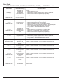
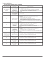
Fault Codes (N62X, N62XX, N82X, and N82XX models) ......................................................................................................................22
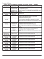
Fault Codes (N64X, N64XXX, N64XIM, N64XIMXX, N84X, N84XXX, N84XIM, and N84XIMXX models) ........................................... 23
Read this manual carefully and understand the contents before you install the refrigerator.
Be aware of possible safety hazards when you see the safety alert symbol on the refrigerator and in this manual. A signal word follows
the safety alert symbol and identies the danger of the hazard. Carefully read the descriptions of these signal words to fully know their
meanings. They are for your safety.
This signal word means a hazard, which if ignored, can cause dangerous personal injury, death, or much
property damage.
This signal word means a hazard, which if ignored, can cause small personal injury or much property
damage.
- This refrigerator is not approved for use as a free standing refrigerator. It is equipped for the use of propane gas only
and can not be changed to use any other fuels (natural gas, butane, etc.).
- Incorrect installation, adjustment, alteration, or maintenance of this refrigerator can cause personal injury, property
damage, or both.
WARNING
!
WARNING
!
CAUTION
!

Installation Manual 3
- Obey the instructions in this manual to install intake and exhaust vents.
- Do not install the refrigerator directly on carpet. Put the refrigerator on a metal or wood panel that extends the full
width and depth of the refrigerator.
- Do not allow anything to touch the refrigerator cooling system.
- Propane gas can ignite and cause an explosion that can result in property damage, personal injury, or death. Do not
smoke or create sparks. Do not use an open ame to examine the propane gas supply line for leaks. Always use two
wrenches to tighten or loosen the propane gas supply line connections.
- Make sure the electrical installation obeys all applicable codes. See “Certication and Code Requirements” section.
- Do not bypass or change the refrigerator’s electrical components or features.
- Do not spray liquids near electrical outlets, connections, or the refrigerator components. Many liquids are electrically
conductive and can cause a shock hazard, electrical shorts, and in some cases re.
- The refrigerator cooling system is under pressure. Do not try to repair or to recharge a defective cooling system.
- The cooling system contains sodium chromate. The breathing of certain chromium compounds can cause cancer. The
cooling system contents can cause severe skin and eye burns, and can ignite and burn with an intense ame. Do not
bend, drop, weld, move, drill, puncture, or hit the cooling system.
- The rear of the refrigerator has sharp edges and corners. To prevent cuts or abrasions when working on the
refrigerator, use caution and wear cut resistant gloves.
Certication and Code Requirements
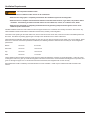
This refrigerator is certied by CSA International as meeting the
latest edition of ANSI Z21.19 / CSA 1.4 standards for installation in
mobile homes or recreational vehicles.
The refrigerator must be installed in accordance with this
“Installation Manual” in order for the Norcold limited warranty to be
in effect. In addition, the installation must conform to the following,
as applicable:
In the United States and Canada:
- Local codes, or in the absence of local codes, the National Fuel Gas Code, ANSI Z223.1/NFPA 54, the Natural Gas and Propane
installation Code, CSA B149.1, ANSI A119.2 Recreational Vehicles Code, and CSA Z240 RV Series, Recreational Vehicles.
- A manufactured home (mobile home) installation must conform with the Manufactured Home Construction and Safety Standard,
Title 24 CFR, Part 3280 [formerly the Federal Standard for Mobile Home Construction and Safety, Title 24 (part 280), and the
current CSA Z240.4, Gas-equipped Recreational Vehicles and Mobile Housing.
- If an external power source is utilized, the appliance, when installed, must be electrically grounded in accordance with local codes
or, in the absence of local codes, the National Electrical code, and ANSI/NFPA 70, or the Canadian Electrical Code, CSA C22.2.
Parts 1 and 2.
All propane gas supply piping and ttings must obey local, state, and national codes about type and size. These components must also
obey the current NFPA 1192 section 2-4, and in Canada with the current CAN 1-6.10 Standard.
Art01290
CAUTION
!

Installation Manual 4
Ventilation Requirements
The completed installation must:
- Make sure there is sufcient intake of fresh air for combustion.
- Make sure the living space is completely isolated from the combustion system of the refrigerator.
- Make sure there is complete and unrestricted ventilation of the ue exhaust which, in gas mode, can produce carbon
monoxide. The breathing of carbon monoxide fumes can cause dizziness, nausea, or in extreme cases, death.
- Make sure the refrigerator is completely isolated from its heat generating components through the correct use of
bafes and panel construction.
Certied installation needs one lower intake vent and one upper exhaust vent. Install the vents exactly as written in this manual. Any
other installation method voids both the certication and the factory warranty of the refrigerator.
The bottom of the opening for the lower intake vent, which is also the service access door, must be even with or immediately below the
oor level. This allows any leaking propane gas to escape to the outside and not to collect at oor level.
CSA International certication allows the refrigerator to have zero (0) inch minimum clearance at the sides, rear, top, and bottom. While
there are no maximum clearances specied for certication, the following maximum clearances are necessary for correct refrigerator
performance:
Bottom 0 inch min. 0 inch max.
Each Side 0 inch min 1/2 inch max.
Top 0 inch min. 1/4 inch max.
Rear 0 inch min. 1 inch max.
These clearances plus the lower and upper vents cause the natural air draft that is necessary for good refrigeration. Cooler air comes
in through the lower vent, goes up around the refrigerator coils where it removes the excess heat from the refrigerator components, and
goes out through the upper vent. If this air ow is blocked or decreased, the refrigerator will not cool correctly.
Each NORCOLD model is certied by CSA International for correct ventilation. Install only the certied vents that are listed in this
manual.
WARNING
!

Installation Manual 5
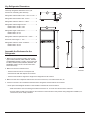
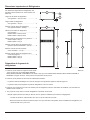
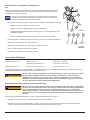
Key Refrigerator Dimensions
These key refrigerator dimensions are for your
reference as necessary (See Art01733).
Refrigerator cabinet width w/o trim - 23.47 in. max. ...1
Refrigerator width overall w/ trim - 24.6 in. ................. 2
Refrigerator cabinet to side trim - 0.80 in. ..................3
Refrigerator cabinet height w/o trim............................4
N600 models - 52.85 in. max.
N800 models - 59.85 in. max.
Refrigerator height overall w/ trim...............................5
N600 models - 54.5 in.
N800 models - 61.5 in.
Refrigerator cabinet to top/bottom trim - 0.93 in. ........ 6
Enclosure wall to hinges - 1.10 in. ..............................7
Refrigerator cabinet to center of handles ...................8
N600 models - 32.5 in.
N800 models - 39.5 in.
Art01733
1
8
7
5
6
4
3
2
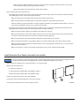
1. Make sure the enclosure is 59.88 - 60.01 inches
high for N82X, N82XXX, N84X, N84XXX, N84XIM,
and N84XIMXX models or 52.88 - 53.01 inches high
for N62X, N62XXX, N64X, N64XXX, N64XIM, and
N64XIMXX models x 23.50 - 23.63 inches wide x
24.00 inches deep.
2. Make sure the oor is solid and level.
- The oor must be metal or a wood panel and
extend the full width and depth of the enclosure.
- The oor must be able to support the weight of the refrigerator and its contents.
3. Make sure there are no adjacent heat sources such as a furnace vent, a hot water heater vent, etc.
4. If there is more than 1/2 inch between either side of the refrigerator and the inside of the enclosure:
- Fill the space with berglass insulation or add a bafe to eliminate the excess clearance.
- Make sure that the rear of the batt-type insulation is between 18 - 19 inches from the face of the enclosure.
- Securely attach the batt-type insulation to the enclosure so that it remains in this position during refrigerator installation, if it
becomes wet, and in windy conditions.
Assemble the Enclosure for the
Refrigerator

Installation Manual 6
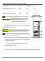
Install the Lower and Upper Vents
1. Using the following chart, decide which vents and rough opening (RO) sizes to use:
Certied Vent P/N RO Height RO Width
Upper Roof Exhaust Cap 622293 N/A N/A
Upper Roof Exhaust Vent 616319 24 in. 5 1/4 in.
Upper Exhaust & Lower Intake - Plastic 621156 13 3/4 in. 21 1/2 in.
Lower Square Corner Intake 616010 9 3/4 in. 19 3/8 in.
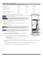
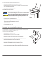
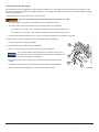
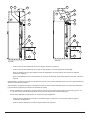
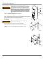
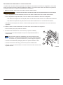
2. Install the lower intake vent (See Art01598, Art01599, and Art01602):
The lower intake vent is also the service access opening for the components
on the rear of the refrigerator.
Make sure the bottom of the opening of the lower intake vent is even
with or immediately below the oor level. This allows any leaking
propane gas to escape to the outside and not to collect at oor level.
- Make sure the bottom of the opening of the lower intake vent [9] is even with or
immediately below the oor level.
- Align the lower intake vent vertically below the coils [10] and the condenser [11] of the
refrigerator.
3. Install the upper exhaust vent:
Make sure that no sawdust, insulation, or other construction debris is
on the refrigerator or in the enclosure. Debris can cause a combustion
hazard and prevent the refrigerator from operating correctly.
Tighten the screws of the upper roof exhaust cap to 10 inch-pounds max. Also
make sure that the air ow around the upper roof exhaust cap is not blocked
or decreased by other roof mounted features such as a luggage carrier, an air
conditioner, a solar panel, etc.
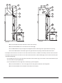
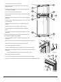
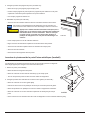
- If the design of the vehicle allows, install the roof exhaust vent [12] directly above the
condenser [11] of the refrigerator (See Art01598):
- Install a bafe [13] to prevent stagnant hot air in the area [14] above the refrigerator.
- Make sure there is less than 1/4 inch clearance [15] between the bafe and the
top of the refrigerator.
- Make sure the bafe is the full width of the inside of the enclosure.
- If the design of the vehicle does not allow you to install the roof exhaust vent directly above the condenser [11] of the refrigerator
(See Art01599):
- Align the roof exhaust vent [12] above the condenser [11] of the refrigerator and move it inboard as necessary.
- Install two bafes [13] to prevent stagnant hot air in the area [14] above the refrigerator.
10
11
9
Art01602
NOTICE
WARNING
!
NOTICE
CAUTION
!

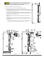
Installation Manual 7
Art01599
20
14
13
12
11
16
9
10
18
17
19
16
19
Art01598
14
9
11
12
13
15
16
10
17
18
15
15
16
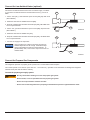
- Make sure the bafes are the full width of the inside of the enclosure.
- Make sure that the bafes are no more than 45° from vertical [20].
- Put one bafe between the top rear edge of the refrigerator and the inside edge of the upper exhaust vent opening.
- Put the other bafe between the outside edge of the upper exhaust vent opening and the side wall of the vehicle.
- If the depth of the enclosure is 24 inches or more and is less than 25 inches, no bafes are necessary at the rear of the enclosure.
- If the depth of the enclosure is 25 inches or more and is less than 26 inches, add two bafes [16] to the rear of the enclosure (See
Art01598 and Art01599).
- Put one bafe 18 inches to 18 1/2 inches above the bottom of the enclosure [17] (4 1/4 inches to 4 3/4 inches above the top of
the lower intake vent opening REF) [18] .
- Put the other bafe at the lowest edge of the condenser [11] of the refrigerator.
- Make sure that the bafes are 1 inch or less [19] from the coils [10] and condenser of the refrigerator.
- Make sure that the bafes are the full width of the inside of the enclosure.

Installation Manual 8
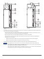
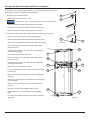
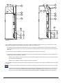
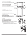
- If the depth of the enclosure is more than 26 inches, install a wood or an aluminum or galvanized sheet solid box bafe [21] in the
rear of the enclosure (See Art01617 and Art01618).
- Make sure that the bottom of the solid box bafe is 18 inches to 18 1/2 inches above the bottom of the enclosure [17] (4 1/4
inches to 4 3/4 inches above the top of the lower intake vent opening REF) [18].
- Make sure that the back of the solid box bafe is perpendicular to the bottom of the enclosure.
- Make sure that the back of the solid box bafe is either against the top of the enclosure or against the angled bafe [13]
(depending on the vehicle design).
- Make sure that the solid box bafe is one inch or less [19] from the coils [10] and condenser of the refrigerator.
- Make sure that the solid box bafe is the full width of the inside of the enclosure.
- If the design of the vehicle does not allow you to install a roof exhaust vent, install an upper side-wall exhaust vent.
The refrigerator is 23.7 in. min. to 24.0 in. max. from the rear of the breaker to the rear of the condenser [22].
N62X, N62XXX, N64X, N64XXX, N64XIM, and N64XIMXX models are 47.1 in. min. to 47.4 in. max. from the bottom
of the refrigerator to the bottom of the refrigerator condenser [23].
N82X, N82XXX, N84X, N84XXX, N84XIM, and N84XIMXX models are 54.1 in. min. to 54.4 in. max. from the bottom
of the refrigerator to the bottom of the refrigerator condenser [23] (See Art01601).
Art01617
14
15
13
12
19
11
21
18
17
10
9
Art01618
14
20
12
13
11
19
21
18
17
10
9
NOTICE

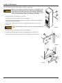
Installation Manual 9
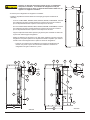
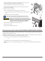
Only use an upper side-wall exhaust vent on refrigerator models
that are equipped with a fan. If you use an upper side-wall exhaust
vent on a refrigerator model that is not equipped with a fan, the
refrigerator cooling performance will be poor.
- Make sure the refrigerator model is equipped with a fan.
- Install the upper side-wall exhaust vent [24] (See Art01592 and Art01593).
- For N62X, N62XXX, N64X, N64XXX, N64XIM, and N64XIMXX models, make sure the
distance [25] from the bottom of the enclosure to the top of the rough opening for the
upper exhaust vent is at least 55 inches.
- For N82X, N82XXX, N84X, N84XXX, N84XIM, and N84XIMXX models, make sure the
distance [25] from the bottom of the enclosure to the top of the rough opening for the
upper exhaust vent is at least 62 inches.
- Align the upper exhaust vent [24] horizontally above the lower intake vent [9] of the
refrigerator.
- To prevent stagnant hot air in the area above the refrigerator, install an aluminum or
galvanized steel sheet bafe [13] between the top of the refrigerator and the top of the
upper exhaust vent.
- Make sure there is less than 1/4 inch clearance between the bafe and the top of
the refrigerator and that the bafe overlaps the refrigerator 1 inch or less.
22
23
Art01601
Art01592
15
13
15
11
213
15
25
24
26
9
10
27
Art01593
27
17
10
9
18
25
21
24
1513
15
11
15
213
CAUTION
!

Installation Manual 10
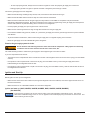
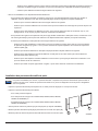
The doors are made to accept decorative panels. The decorative panels must be 3/16 inch or less in thickness. Install
the decorative door panels in the refrigerator doors before installing the refrigerator in the vehicle.
- Make an upper door panel that is 21 19/32 inches wide x 14 17/32 inches high.
- Make a lower door panel that is:
- 21 19/32 inches wide and
- 31 5/8 inches high (for N62X, N64X, and N64XIM models) or
- 38 5/8 inches high (for N82X, N84X, and N84XIM models).
- Pull the panel retainer [37] off each door (See Art00965).
- Push the decorative door panel [38] into the slots of the door [39].
- Push each panel retainer into the slot on the edge of the door.
Install Decorative Door Panels (non-metal door models)
- Make sure that the bafe is against the wall of the vehicle at the top of the upper exhaust vent and 1/4 inch or less
from the top of the opening for the upper exhaust vent [15].
- Make sure the bafe is the full width of the inside of the enclosure.
- When using an upper side-wall exhaust vent:
- If the depth of the enclosure is 24 inches or more and is less than 26 inches [27], install a bent aluminum or galvanized steel
sheet bafe [26] to the rear of the enclosure (See Art01592).
- Make sure that the bend of the bafe is the full width of the inside of the enclosure.
- Make sure that the bend of the bafe is ush with the bottom edge of the upper intake vent door frame.
- Make sure that the top edge of the bafe is 1/4 inch [213] below the bottom of the condenser and that there is 1/4 inch or
less clearance [15] between the rear of the condenser and the bafe.
- If the depth of the enclosure is more than 26 inches [27], install a wood or an aluminum or galvanized steel sheet solid box
bafe [21] between the lower intake vent and the upper exhaust vent (See Art01593).
- Make sure that the solid box bafe is the full width of the inside of the enclosure.
- Make sure that the bottom of the solid box bafe is 18 inches to 18 1/2 inches above the bottom of the enclosure [17] (4
1/4 inches to 4 3/4 inches above the top of the lower intake vent opening REF) [18] .
- Make sure that the back of the solid box bafe is perpendicular to the bottom of the enclosure.
- Make sure that the horizontal top of the solid box bafe is even with the bottom edge of the upper exhaust vent [24].
- Make sure that the vertical top edge of the bafe is between 1/4 inch [213] below the condenser and 1 1/2 inches above
the bottom of the condenser.
- Make sure that there is 1/4 inch or less clearance [15] between the rear of the condenser and the bafe.
Art00965
37
38
39
NOTICE

Installation Manual 11
Put the refrigerator in position (See Art00962, Art00963, and Art00964):
Make sure the combustion seal [28] is not broken, is completely around
the refrigerator mounting anges, and is between the mounting anges
and the wall of the enclosure If the seal is not complete, exhaust fumes
can be present in the living area of the vehicle. The breathing of exhaust
fumes can cause dizziness, nausea, or in extreme cases, death.
- Push the refrigerator completely into the enclosure.
- Put the upper trim piece [40] onto the front of the refrigerator.
- Put screws [41] through the upper and lower mounting anges on the front of the refrigerator
and into the enclosure wall and oor.
- Put a cap [42] on each of the screw holes in the upper trim piece [40] on the front of the
refrigerator.
Do not omit the bottom trim piece. This piece is part of the combustion
seal.
- Push the bottom trim piece [29] onto the front of the refrigerator.
- Put two screws [41] through the trim piece, the mounting ange, and into the oor.
- Put screws through mounting ange on the rear of the refrigerator and into the oor.
Install the Refrigerator
Art00962
28
29
Art00963
41
42
40
Art00964
41
29
41
WARNING
!
WARNING
!

Installation Manual 12
This refrigerator has cabinet hinges that allow you to change the direction the door opens
by moving the hinges on a diagonal to the opposite side.
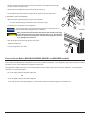
1. Remove the doors (See Art01726):
- Remove the storage bins from the doors.
Do not mix the upper and lower hinge pins because they are different.
- Remove and save the upper hinge pin [63] from each hinge.
- Pull the door latch and remove each door from the refrigerator.
- Remove and save the lower hinge pin [64] from each hinge.
2. Change the position of the cabinet hinges and the strike plate (See Art01728):
- Remove and save the screws from the strike plate [65a].
- Remove the two plastic hole caps that are near the strike plate.
- Remove the L-shaped plastic covers that are opposite the hinges.
- Remove and save the screws from the upper cabinet hinge
[66a] of each door.
- Put each of these hinges on the other side of the refrigerator
as the lower hinge [66b].
- Attach each of these hinges with screws.
- Remove and save the screws from the lower cabinet hinge
[67a] of each door.
- Put each of these hinges on the other side of the refrigerator
as the upper hinge [67b].
- Attach each of these hinges with screws.
- Put the L-shaped plastic covers over the holes that were used
by the hinges.
- Remove and save the screw [41] from the front box [68] (See
Art01573).
- Pull the front box away from the refrigerator and out from under
the controls [69].
- Reverse the front box and put it on the opposite side of the
controls.
- Attach the front box to the refrigerator with the screw.
- Put the strike plate on the opposite side of the refrigerator
[65b].
- Put the two round plastic caps into the holes that are near the
strike plate.
66
Art01726
63
64
67
Reverse the Door Swing-Nonmetal Doors (optional)
Art01728
66a
67a
65b
66a
66b
67a
65a
67b
67b
66b
NOTICE

Installation Manual 13
3. Change the position of the door handles (See Art01727):
- Remove the screws [41] and door handle [70] from each door.
- Reverse each door handle and put the lower door handle on the upper door and the
upper door handle on the lower door.
- Attach each door handle with the screws.
4. Reinstall the doors (See Art01726):
- Turn the lower hinge pins into the lower cabinet hinges.
To prevent damage to the threads of the hinge pins, turn the hinge pins by
hand until tight and then tighten with a screwdriver.
Apply Loctite removable thread locker (blue) to the threads of the
hinge screws before assembly to prevent loosening during use.
Do not allow Loctite to contact any of the plastic surfaces of the
refrigerator because it can damage those surfaces.
- Put each door down onto the lower hinge pin.
- Align the holes in the upper hinges and hold in this position.
- Turn the upper hinge pin into the hinges of each door.
- Tighten the hinge pins.
- Put the storage bins in the doors.
41
70
Art01727
Reverse the Door Swing-Metal Doors (optional)
This refrigerator has door hinges that allow you to change the direction the door opens by
moving the hinges on a diagonal to the opposite side.
1. Remove the doors (See Art00986):
- Remove the storage bins from the doors.
- Remove and save both hinge pins [71] from each door.
- Pull the door latch and remove each door away from the refrigerator.
2. Change the position of the cabinet hinges and the strike plate (See Art01728):
- Remove and save the screws from the strike plate [65a].
- Remove the two plastic hole caps that are near the strike plate.
- Remove the L-shaped plastic covers that are opposite the hinges.
- Remove and save the screws from the upper cabinet hinge [67a] of each door.
- Put each of these hinges on the other side of the refrigerator as the lower hinge [67b].
71
73
66
67
74
Art00986
NOTICE
CAUTION
!

Installation Manual 14
- Attach each of these hinges with screws.
- Remove and save the screws from the lower cabinet hinge
[66a] of each door.
- Put each of these hinges on the other side of the refrigerator
as the upper hinge [66b].
- Attach each of these hinges with screws.
- Put the L-shaped plastic covers over the holes that were used
by the hinges.
- Remove and save the screw [41] from the front box [68] (See
Art01573).
- Pull the front box away from the refrigerator and out from under
the controls [69].
- Reverse the front box and put it on the opposite side of the
controls.
- Attach the front box to the refrigerator with the screw.
- Put the strike plate on the opposite side of the refrigerator
[65b].
- Put the two round plastic caps into the holes that are near the
strike plate.
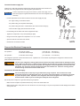
3. Change the position of the door handles and the door hinges
(See Art01695, Art00985, and Art00986):
- Remove the plastic cap that is opposite the upper hinge of the
upper door.
- Remove the cap screws [72] from the door handle [70] and door hinge [73].
- Remove the screws [41] and door handle from each door.
- Remove the upper hinge of each door.
- Put each of these hinges on the other side of the door as the lower hinge.
- Attach each of these hinges with the cap screws that were removed from the
other side.
- The recommended torque for each cap screw [72] is 35 in.-lbs.
- Remove the lower hinge of each door.
- Put each of these hinges on the other side of the door as the upper hinge.
- Attach each of these hinges with the cap screws that were removed from the other side.
Art01728
66a
67a
65b
66a
66b
67a
65a
67b
67b
66b
Art01573
69
41
68
Art01695
41
70
72

Installation Manual 15
- Reverse each door handle and put the lower door handle on the upper door and the up-
per door handle on the lower door.
- Attach each door handle with a cap screw [72] and screws [41].
- Put the plastic cap into the hole that is opposite the upper hinge of the upper door.
4. Reinstall the doors (See Art00986):
- Make sure each hinge bushing [74] is in the correct position.
- Put each hinge bushing into the bottom side of each door hinge.
- Put each door in the position on the refrigerator.
To prevent damage to the threads of the hinge pins, turn the hinge pins by
hand until tight and then tighten with a screwdriver.
Apply Loctite removable thread locker (blue) to the threads of the hinge
screws before assembly to prevent loosening during use. Do not allow
Loctite to contact any of the plastic surfaces of the refrigerator because
it can damage those surfaces.
- Align the hinges and put the hinge pins into each door.
- Tighten the hinge pins.
- Put the storage bins in the doors.
Art00966
49
50
51
121
73
72
Art00985
The ice maker is assembled to the refrigerators at the factory as optional equipment. If the refrigerator does not have a factory installed
ice maker, one can not be added to the refrigerator at a later time.
The refrigerator installer must connect a cold water supply line to the solenoid valve at the rear of the refrigerator. The following are
necessary to connect the icemaker:
- 1/4 in. OD copper tubing for the water supply line.
OR
- 1/4 in. OD plastic tubing for the water supply line.
- 1/4 in. shut off valve in the water supply line. This should be easily accessible through the lower intake vent.
Connect the Ice Maker (N64XIM, N64XIMXX, N84XIM, and N84XIMXX models)
CAUTION
!
NOTICE

Installation Manual 16
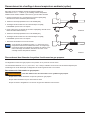
Connect the water supply line:
Install a 1/4 in. OD water supply line [43] from the water shut off valve of the vehicle to the
solenoid water valve [44] at the rear of the refrigerator (See Art01014):
A brass compression nut [45], a brass sleeve, a plastic sleeve [46] , and a
brass insert [47] are supplied and attached to the rear of the refrigerator (See
Art01755).
- Put the compression nut and then the sleeve onto the water supply line [43].
- For copper tubing, use the brass sleeve.
- For plastic tubing, use the plastic sleeve [46].
- For plastic tubing with .040 in. wall thickness, also use the brass insert [47].
- Flush the water supply line until the water is clear.
- Put the tubing into the water valve until it is against the stop.
- Tighten the compression nut by hand (hard nger tight).
- Using two wrenches, tighten the compression nut 1 ½ to 2 turns.
- Open the water shut off valve of the vehicle.
- Examine the connections for leaks.
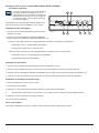
Connect the Electrical Components
AC Operation 120 volts AC voltage (132 volts max. - 108 volts min.)
12 volts DC control voltage (15.4 volts max. - 10.5 volts min.)
DC Operation 12 volts DC control voltage (15.4 volts max. - 10.5 volts min.)
This refrigerator operates on these electrical sources. Operation out of these limits may damage the refrigerator’s electrical circuit
parts and will void the warranty.
The rear of the refrigerator cooling system has hot surfaces and sharp surfaces that can damage electrical
wiring. Make sure that there is a good clearance between all electrical wiring and the cooling system of the
refrigerator. Position any electrical wiring within the refrigerator enclosure opposite the burner side of the
refrigerator. Do not put any electrical wiring through the roof exhaust vent. Failure to correctly position
electrical wiring can result in electrical shock or re.
Connect the 120 volts AC supply:
Connect the AC power cord(s) only to a grounded three-prong receptacle. Do not remove the round
ground prong from any of the AC power cords. Do not use a two prong adapter or an extension cord with
any of the AC power cords. Operation of the refrigerator without correct ground can cause dangerous
electrical shock or death if you are touching the metal parts of the refrigerator.
Put the AC power cord(s) into a grounded three-prong receptacle:
- Make sure the receptacle is positioned within easy reach of the lower intake vent.
- Make sure the power cord(s) does not touch the burner cover, the ue pipe, or any hot component that could damage the insulation
of the power cord.
43
44
45
48
Art01014
NOTICE
WARNING
!
WARNING
!

Installation Manual 17
Connect the 12 volts DC supply:
As the distance from the vehicle battery to the refrigerator increases, the correct AWG wire size and fuse size also increases. If the
wire size is too small for the distance, a voltage drop occurs. The voltage drop decreases the output of the system heater and causes
poor cooling performance.
1. Determine the min. wire size and the max. fuse size to use:
If you use an incorrect wire size and/or fuse size, electrical re can result.
- On 2-way models, use a minimum of 18 AWG wire and a maximum 6 Amp fuse.
- On 3-way models, measure the distance from the vehicle battery to the refrigerator.
- If the distance is 0 - 20 feet, use a minimum of 10 AWG wire and a maximum 30 Amp fuse.
- If the distance is over 20 feet, use a minimum of 8 AWG wire and a maximum 40 Amp fuse.
- If the wire size is larger than the min. size, use the correct fuse per RVIA A119.2 standard or local codes.
2. Install a fuse in DC power supply wires between the battery and the refrigerator:
- Put fuse as close to the battery as possible.
3. Connect the DC power supply wires (See Art00966):
- Attach a 1/4 inch Quick Connect terminal to each DC power supply wire.
Do not use the chassis of the refrigerator or the vehicle frame as one of
the conductors. Attach the DC power supply wires only to the battery and
the power board [49] of the refrigerator.
- Push the positive DC power wire [50] onto the power board terminal that is marked
12VDC.
- Push the DC ground wire [51] onto the power board terminal that is marked GND.
- Make sure each DC power supply wire is on the correct polarity terminal.
Art00966
49
50
51
121
WARNING
!
NOTICE

Installation Manual 18
Connect the Propane Gas Components
This refrigerator operates on propane gas at a pressure of 11 inches Water Column Propane.
The controls operate on 12 volts DC (10.5 volts min. - 15.4 volts max.). Operation out of these limits can damage the refrigerator
electrical circuit parts and will void the warranty.
Connect the propane gas supply system:
Be very careful when working on or near the propane gas system.
- Do not smoke, or use an open ame near the propane gas system.
- Do not use an open ame to examine for leaks.
- Do not connect the refrigerator to the propane gas tank without a pressure regulator between them.
WARNING
!
Connect the Low Ambient Heater (optional)
Connect the low ambient heater wires to the 12 volts DC supply. The black
(+) wire of the low ambient heater is 16 AWG and the brown (-) wire is 18
AWG.
1. Cut the 12V input (+) wire behind the quick connect [269]; strip both ends
(See Art02316).
2. Solder the wires with the 16AWG black wire [266].
3. Wrap the soldered wires with black electrical tape [268]; BE SURE there
are no exposed strands.
4. Cut the 12V ground wire behind the quick connect [269]; strip both ends
(See Art02317).
5. Solder the wires with the 18AWG wire [267].
6. Wrap the soldered wires with black electrical tape [268] ; BE SURE there
are no exposed strands.
7. Connect 12V supply to the input wires.
This kit supplies DC voltage to the heater any time the
ambient temperature is low enough. Extended storage
during cold weather will drain the vehicle batteries. To
prevent battery drain, remove the 3 amp fuse from the low
ambient heater.
Art02316
268
269
266
Art02317
268
269
267
NOTICE

Installation Manual 19
Ignition and Start Up
- To avoid a propane gas leak, always use two wrenches to tighten or loosen the propane gas supply line connections.
- Leaking propane gas leak can ignite or explode and result in dangerous personal injury or death.
Connect the gas supply line to the refrigerator:
- Make sure that all tubing and ttings obey all local, state, and national codes about size and type.
- Make sure that all exible metal connectors obey the current CAN1-6.10 Standard.
- Make sure that the materials used for the gas supply line obey both the current ANSI A 119.2 (NFPA 1192) and CSA Z240
Standards on Recreational Vehicles. Norcold recommends the use of 3/8 inch copper tubing as the gas supply line and requires a
3/8 inch SAE (UNF 5/8-18) male are tting as the connection to the refrigerator.
- Put the propane gas supply line up through the oor of the enclosure.
- Make sure the hole through the oor is large enough allow clearance for the gas supply line.
- Put a weather resistant seal (grommet, sealant, etc.) around the gas supply line where it goes through the oor to prevent vibration
and abrasion.
- To prevent vibration and abrasion, make sure that the gas supply line is not against anything in the enclosure.
- Attach the gas supply line to the bulkhead tting of the refrigerator.
Examine the gas supply system for leaks:
Do not allow the leak detecting solution to touch the electrical components. Many liquids are electrically
conductive and can cause electrical shorts and in some cases, re.
Use a leak detecting solution to examine the gas supply line and all propane gas connections for leaks.
If you use compressed air for the test:
- The pressure of the compressed air at the manual shut off valve of the refrigerator must not be more than 1/2 psig (14 inches Water
Column).
- If the pressure of the compressed air is more than 1/2 psig (14 inches Water Column), remove the gas supply line from the
bulkhead tting of the refrigerator before the test.
- If the pressure of the compressed air is equal to or less than 1/2 psig (14 inches Water Column), close the manual shut off valve of
the refrigerator before the test.
Before ignition or start up of the refrigerator:
- Make sure the air ow in the lower intake vent, through the refrigerator coils and condenser, and out the upper exhaust vent is not
blocked or decreased.
- Make sure there are no combustible materials in or around the refrigerator.
Ignition and start up: (N64X, N64XXX, N64XIM, N64IMXX, N84X, N84XXX, N84XIM, N84IMXX)
(See Art01018)
If the gas does not ignite in 30 seconds, the gas safety valve of the refrigerator automatically closes. The controls
either select a different energy source or “no” “FL” appears in the center display and you will hear an alarm sound. This
means that the gas did not ignite.
WARNING
!
NOTICE

Installation Manual 20
f the gas does not ignite after several attempts, refer to the
“Fault Codes” section of this manual.
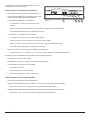
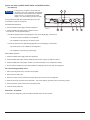
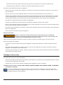
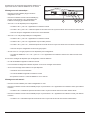
Set the controls to automatic mode operation:
- Push the ON / OFF button [30] to turn the refrigerator on.
- Push and hold the MODE button [31] until the letters “AU”
show in the center display [33] and then release.
- If 120 volts AC is available to the refrigerator:
- The letters “AU” and then “AC” show in the center
display.
- After ten seconds, the “AU” and then “AC” go off and only a green power ON light remains.
- This means that the refrigerator is operating on AC electric.
- If 120 volts AC is not available to the refrigerator:
- The letters “AU” and then “AC” show in the center display.
- After ve seconds, the “AU” and then “LP” show in the center display.
- After ten seconds, the “AU” and the “LP” go off and only a green power ON light remains.
- This means that the refrigerator is operating on propane gas.
- If neither 120 volts AC nor propane gas is available to the refrigerator:
- The fault codes “no” “AC” and then “no” “FL” show in the center display and an audible alarm sounds.
If an energy source is available to the refrigerator, but is not operating correctly:
- A fault code shows in the center display.
- The refrigerator controls try to change to a less efcient energy source.
- If a less efcient energy source is not available:
- An audible alarm starts.
- A fault code shows in the center display.
- Refer to the “Fault Codes” section of this manual.
Set the controls to manual mode operation:
- Push the ON / OFF button to turn the refrigerator on.
- Push and hold the MODE button until the letters “ AC” show in the center display and then release.
- After ten seconds, the “AC” goes off and only a green power ON light remains.
- Push and hold the MODE button until the letters “LP” show in the center display and then release.
- After ten seconds, the “LP” goes off and only a green power ON light remain
ON
TEMP
SET
MODE
ON-OFF
1-COLD COLDEST-9
Art01018
30
3132
33
Page is loading ...
Page is loading ...
Page is loading ...
Page is loading ...
Page is loading ...
Page is loading ...
Page is loading ...
Page is loading ...
Page is loading ...
Page is loading ...
Page is loading ...
Page is loading ...
Page is loading ...
Page is loading ...
Page is loading ...
Page is loading ...
Page is loading ...
Page is loading ...
Page is loading ...
Page is loading ...
Page is loading ...
Page is loading ...
Page is loading ...
Page is loading ...
Page is loading ...
Page is loading ...
Page is loading ...
Page is loading ...
-
 1
1
-
 2
2
-
 3
3
-
 4
4
-
 5
5
-
 6
6
-
 7
7
-
 8
8
-
 9
9
-
 10
10
-
 11
11
-
 12
12
-
 13
13
-
 14
14
-
 15
15
-
 16
16
-
 17
17
-
 18
18
-
 19
19
-
 20
20
-
 21
21
-
 22
22
-
 23
23
-
 24
24
-
 25
25
-
 26
26
-
 27
27
-
 28
28
-
 29
29
-
 30
30
-
 31
31
-
 32
32
-
 33
33
-
 34
34
-
 35
35
-
 36
36
-
 37
37
-
 38
38
-
 39
39
-
 40
40
-
 41
41
-
 42
42
-
 43
43
-
 44
44
-
 45
45
-
 46
46
-
 47
47
-
 48
48


Norcold N82 Installation guide
- Category
- Fireplaces
- Type
- Installation guide
- This manual is also suitable for
Ask a question and I''ll find the answer in the document
Finding information in a document is now easier with AI
in other languages
- français: Norcold N82 Guide d'installation
Related papers
-
Norcold N260 Installation guide
-
-
Norcold N62/N82 Series Owner's manual
-
-
-
-
-
-
-
Other documents
-
 DURA-LIFT DLADMH Installation guide
-
 NORCOLD INC N3104AGR User manual
-
Dometic RM1350 User manual
-
Dometic RM2351, RM2354, RM2410, RM2451, RM2454, RM2510, RM2551, RM2554, RM2620, DM2652, DM2662, DM2663, NDA140, RM3762, RM2820, DM2852,DM2862, RM3962, NDM1062, RM1350, RM1350SL Operating instructions
-
-
-
 Winnebago 1999 Vectra Grand Tour User manual
-
Dometic RMS8550 User manual
-
-
 Winnebago 2001 Chieftain User manual


