Page is loading ...

EConnect™ Wireless Thermostat Kit TA7210
With Equipment Interface Module
Installation guide for:
• Wireless equipment interface module
• EConnect™ wireless thermostat
• Wireless remote control
• Wireless outdoor air sensor
IMPORTANT INSTRUCTIONS
Need Help?
For assistance with this product please visit www.aubetech.com
or call Honeywell Customer Care toll-free at 1-800-831-2823.
ELECTRICAL HAZARD
Can cause electrical shock or equipment damage. Disconnect power
before beginning installation.
Must be installed by a certified electrician. Read these instructions
carefully. Failure to follow these instructions can damage the product or
cause a hazardous condition.
System
Installation
Guide
69-2472EF-01 (Aube TA7210 System Installation Guide).book Page 1 Wednesday, June 29, 2011 1:15 PM

Installation Guide
2
The equipment interface module (EIM) allows you to control a baseboard heater, a
convector or a fan-forced heater in a 120-volt, 208-volt or 240-volt application from a
EConnect™ wireless thermostat.
Installation procedure
Install the equipment interface module (EIM)............................................... Pages 3 - 6
Install batteries in wireless devices..................................................................... Page 7
Link all devices to wireless network........................................................... Pages 7 - 10
Exit wireless setup.............................................................................................Page 11
Customize thermostat (installer setup)......................................................Pages 11 - 18
Mount thermostat and outdoor sensor..................................................... Pages 19 - 20
For error codes, see page 20.
To verify the signal strength, see page 21.
To replace a wireless device, see pages 21-22.
For specifications and replacement parts, see page 23.
SAVE THESE INSTRUCTIONS
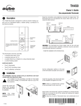
System installation at a glance
1.
Remote
control
Thermostat
Outdoor
air sensor
Thermostat
EIM in remote
junction box
EIM in heater
Electrical
panel
Heater
Supply wires
Wireless connection
69-2472EF-01 (Aube TA7210 System Installation Guide).book Page 2 Wednesday, June 29, 2011 1:15 PM

EConnect™ TA7210
3
Determine the location
The equipment interface module (EIM) consists of a relay and an antenna. They can be
installed either in the wiring compartment of the baseboard heater or in a 4-11/16” square
junction box.
• Installing the EIM in a baseboard heater
You can install the EIM in the wiring
compartment of the baseboard heater if you
have any of the heaters listed in the following
table:
• Installing the EIM in a 4-11/16” square junction box
You can use a 4-11/16” square junction box in either of
the following conditions:
• You have a convector or fan-forced heater.
• You cannot install or do not wish to install the EIM in
the wiring compartment of the baseboard heater.
Install the Equipment Interface Module (EIM)
2.
Install EIMs at a minimum distance of 2 feet (0.6 m) of each other. This minimum
distance still applies even if the EIMs are on opposite sides of a wall.
Manufacturer / brand Series
Cadet F
Global Commander CCB
King Electrical K, CB, KP, M
Marley 2500, BKOC, QMKC
Ouellet ODBA, ODI, ODIA, OFM, OPR
Stelpro CBB, N, SCA, SCAS
TPI 2900C, 2900S, 3700, 3900
The product has been tested for compatibility with the heaters listed above. If your
heater is not on the list, install the EIM on a 4-11/16” square junction box or replace
it with one listed.
The junction box can be installed anywhere in the
house; for example, near the main electrical panel.
Relay
Antenna
Relay
Antenna
69-2472EF-01 (Aube TA7210 System Installation Guide).book Page 3 Wednesday, June 29, 2011 1:15 PM

Installation Guide
4
Installation in a baseboard heater
ELECTRICAL HAZARD
Can cause electrical shock or equipment damage. Disconnect AC power before
beginning installation.
Wiring must comply with local electrical codes. Use special CO/ALR solderless connectors if
supply wires are made of aluminum.
Disconnect the heater wires from the supply wires. If the heater has a built-in thermostat, remove it.
1) Remove the knockout on the side of the heater.
2) Remove the locknut from the antenna and peel off
the adhesive backing. Feed the antenna cable
through the knockout and install the antenna
vertically as shown. Put the locknut and tighten.
3) Clean the back panel inside the wiring
compartment where the relay will be installed. Peel
the adhesive backing off the relay and stick the
relay on the back panel.
4) Connect the heater wires and the supply wires to
the relay.
See page 6 if you are connecting more than one
heater.
5) Insert the antenna plug into the relay receptacle
until you hear a click.
6) Put the heater cover back. (If a built-in thermostat
was removed, install one of the supplied plugs to
cover the hole on the existing cover.) Apply power
to the heater. Do not install the antenna cover yet.
ELECTRICAL HAZARD
Can cause electrical shock. Install heater cover
plate before applying power.
Relay wires must be at the top
L2 L1 : For 240V application
N L : For 120V application
BlueBlue
BlackBlack
RedRed
Install plug if
applicable.
69-2472EF-01 (Aube TA7210 System Installation Guide).book Page 4 Wednesday, June 29, 2011 1:15 PM

EConnect™ TA7210
5
Installation in a 4-11/16'' square junction box
ELECTRICAL HAZARD
Can cause electrical shock or equipment damage. Disconnect AC power before
beginning installation.
Wiring must comply with local electrical codes. Use special CO/ALR solderless connectors if
supply wires are made of aluminum.
1) Mount the junction box on the wall. Punch out
knockout(s), install strain relief bushing(s) and feed
the supply wires and the heater wires. Punch out
another knockout to install the antenna (step 2).
2) Remove the locknut from the antenna and peel off
the adhesive backing. Feed the antenna cable
through the knockout opening and mount the
antenna. Put the locknut and tighten.
3) Clean the interior side of the junction box where the
relay will be installed. Peel off the adhesive backing
of the relay module and stick the relay inside the
junction box.
4) Connect the supply wires and heater wires to the
relay.
See page 6 if you are connecting more than one
heater.
5) Insert the antenna plug in the relay receptacle until
you hear a click.
6) Install a cover plate on the junction box and
apply power to the heater. Do not put the antenna
cover back yet.
ELECTRICAL HAZARD
Can cause electrical shock. Install junction box
cover plate before applying power.
Relay wires must be at the top
To heater
L2 L1 : For 240V application
N L : For 120V application
Blue
Blue
Black
Black
Red
Red
69-2472EF-01 (Aube TA7210 System Installation Guide).book Page 5 Wednesday, June 29, 2011 1:15 PM

Installation Guide
6
Connecting multiple heaters to the same EIM
Connecting multiple EIMs on the same circuit
L2 L1 : For 240V application
N L : For 120V application
Blue
Blue
Black
Black
Red
Red
The maximum number of heaters per EIM
is limited to a maximum load of 12.5 A
Remote junction box or
heater wiring compartment
L2 L1 : For 240V application
N L : For 120V application
Blue
Blue
Black
Black
Red
Red
Blue
Blue
Black
Black
Red
Red
The maximum number of EIMs is 8 per thermostat.
Remote junction box or
heater wiring compartment
Remote junction box or
heater wiring compartment
69-2472EF-01 (Aube TA7210 System Installation Guide).book Page 6 Wednesday, June 29, 2011 1:15 PM

EConnect™ TA7210
7
Start wireless setup
Press the EIM Connect button to place it in wireless setup. When the amber light changes
to a green flashing light, you can begin to link devices to the wireless network (see pages
7-10).
Install batteries in wireless devices
3.
Thermostat Remote control
(optional)
Outdoor air sensor
(optional)
Install 2 AA alkaline batteries Install 3 AA alkaline batteries Install 2 AA lithium batteries
Link all devices to wireless network
4.
If the amber light changes to a red light
instead, there is another EIM currently in
wireless setup. Press the Connect button
on the other EIM to exit its wireless setup.
If the green flashing light disappears (after
a delay of 15 minutes) before you have
time to link all your devices, press the
Connect button again.
Connect button
* Flashing green: Ready for connection
Steady green: Connection established
Steady red: Connection failure
Connect LED *
69-2472EF-01 (Aube TA7210 System Installation Guide).book Page 7 Wednesday, June 29, 2011 1:15 PM

Installation Guide
8
Link thermostat and EIM to wireless network
Perform the following steps on the thermostat:
# Display Button Step
1)
The Connexion (link)
menu appears when you
connect the thermostat to
wireless network for the
first time. Press Ok to
select Zone.
2)
Press or to change
the zone name (optional;
see page 17) and press
Ok.
3)
Press Ok to select
Connecter (connect).
4)
SUCC (success) confirms
the connection is
successful. Press Sortir
(exit) once to link another
EIM (see page 9) or 3
times to return to home
screen.
If an error code (E followed by a number) appears on the screen, see its explanation
on page 20.
69-2472EF-01 (Aube TA7210 System Installation Guide).book Page 8 Wednesday, June 29, 2011 1:15 PM

EConnect™ TA7210
9
Link additional EIM to wireless network (optional)
1) If the green light on the previously-linked EIM is flashing, press its Connect button. The
green light will become steady.
2) Press the Connect button on the next EIM you wish to link and wait for its green
flashing light.
Perform steps 1 to 6 for each additional EIM. You can link a maximum of 8 EIMs to
the wireless network.
Skip steps 3 and 4 if the thermostat is displaying the Connexion menu (as
shown in step 5).
# Display Button Step
3)
Press and hold the right
center button for 5 secs.
4)
From the installer’s setup
menu, press to select
Connexion (link) and
press Ok.
5)
Press to select
Connecter autre (connect
more) and press Ok.
6)
SUCC (success) confirms
the connection is
successful. Press Sortir
(exit) once and go back to
step 1 to link another EIM
or press Sortir (exit) 3
times to return to home
screen.
69-2472EF-01 (Aube TA7210 System Installation Guide).book Page 9 Wednesday, June 29, 2011 1:15 PM

Installation Guide
10
Link outdoor sensor to wireless network (optional)
1) Make sure the Connect light on the EIM is
flashing (see page 7).
2) Press the Connect button on the back of the
sensor.
3) After 15 seconds, check if the thermostat is displaying a value for the outdoor
temperature reading.
Link remote control to wireless network (optional)
1) Make sure the Connect light on the EIM is flashing (see page 7).
2) Press CONNECT at the remote
control.
3) When the remote control displays
Connected (after a short delay),
press DONE.
4) Press NO at the next screen to save
and exit. (Or press YES and repeat
steps 1-4 to link to another network).
If you have more than one wireless thermostat,
make sure to activate the wireless setup from
an EIM linked to the thermostat. For example,
to display the outdoor temperature on
thermostat Y, you must activate the wireless
setup from either EIM B or C, not A.
If you have more than one wireless thermostat, repeat steps 1 and 3 for each thermostat.
If you have more than one wireless thermostat, make sure to activate the wireless setup
from an EIM linked to the thermostat. For example, to link the remote control to thermostat
Y, you must activate the wireless setup from either EIM B or C, not A.
Press and
release
Remote
control
Thermostat X
Thermostat Y
EIM A
EIM B
EIM C
Outdoor
sensor
Bathroom
wireless network
Bedroom
wireless network
CONNECT
WIRELESS SETUP
NOYES
CONNECT MORE?
Press to link to
another network
Press to
save and exit
69-2472EF-01 (Aube TA7210 System Installation Guide).book Page 10 Wednesday, June 29, 2011 1:15 PM

EConnect™ TA7210
11
1) Press the EIM Connect button. Its green flashing light will change to a steady green
light.
2) Put the cover back on the antenna module.
Accessing the installer setup menu
• To access the installer setup menu from the home
screen, press and hold the right center button for 5
secs.
Navigating the menus
• Press or to navigate the menus and setup
functions.
• Press Ok to select the flashing menu or setup function.
Modifying the settings
• Press or to modify the displayed setting.
• Press Ok to save the displayed setting. The setting will
flash to confirm that it has been saved.
Exiting the menus
• Press Sortir (exit) once to return to the previous menu
or as many times as necessary to return to the home
screen.
Exit wireless setup
5.
If you do not press the Connect button, the EIM will automatically exit wireless setup
after 15 minutes of inactivity.
Customize the thermostat
6.
If you press Sortir (exit) after you have changed
a setting, the new setting will not be saved.
Make sure you press Ok to save the new setting
before you press Sortir (exit).
69-2472EF-01 (Aube TA7210 System Installation Guide).book Page 11 Wednesday, June 29, 2011 1:15 PM

Installation Guide
12
Installer setup table
Temperature unit / Time format
Follow this procedure to select the temperature unit (°C or °F) and time format (12h or 24h).
Setup function Options Default setting To modify, see
Temperature unit °C / °F °C Page 12
Time format 12h / 24h 24h Page 12
Minimum setpoint 5°C to 30°C (41°F to 86°F) 5°C (41°F) Page 13
Maximum setpoint 5°C to 30°C (41°F to 86°F) 30°C (86°F) Page 13
Programmable mode On / Off On Page 14
Keypad lock None / Partial / All None Pages 15
Zone name 1, ..., 57 52 Pages 16-17
Adaptive Intelligent Recovery On / Off On Page 18
Anti-freeze On / Off On Page 18
To set the date & time, the schedule and the automatic daylight savings, refer to
User’s Guide.
The time format selection is available only if the thermostat is in programmable
mode.
# Display Button Step
1)
From the installer’s setup
menu, press Ok to select
the Format menu.
2)
Press or to change
the temperature unit. Press
Ok.
3)
Press or to change
the time format. Press Ok.
69-2472EF-01 (Aube TA7210 System Installation Guide).book Page 12 Wednesday, June 29, 2011 1:15 PM

EConnect™ TA7210
13
Minimum and maximum setpoints
Follow this procedure to set the minimum and maximum setpoint temperature.
# Display Button Step
1)
From the installer’s setup
menu, press to select
Consignes (setpoints) and
press Ok.
2)
Press Ok to select Min.
3)
Press or to change
the minimum setpoint.
Press Ok.
4)
Press Ok to select Max.
5)
Press or to change
the maximum setpoint.
Press Ok.
6)
Press Sortir (exit) once to
return to installer’s setup
menu or twice to return to
home screen.
69-2472EF-01 (Aube TA7210 System Installation Guide).book Page 13 Wednesday, June 29, 2011 1:15 PM

Installation Guide
14
Programmable mode
The thermostat is factory-set as a 7-day programmable thermostat. To set it as a non-programmable
thermostat, proceed as follows:
Copy
Use this function to copy the configuration settings, the schedule settings or both to other EConnect™
wireless thermostats in your house. This function is available only if the thermostat is connected either to a
remote control or outdoor sensor. The settings are copied to other thermostats connected to the remote
control or outdoor sensor.
# Display Button Step
1)
From the installer’s setup
menu, press to select
Horaire (schedule) and
press Ok.
2)
Press or to select
Non and press Ok.
# Display Button Step
1)
From the installer’s setup
menu, press as needed
to select Copie and press
Ok.
2)
Press or to select
Horaire (schedule),
Configuration or both.
Press Ok.
3)
Patientez (wait) may
appear for several
minutes. When SUCC
(success) appears, press
Sortir (exit) to return to
home menu.
69-2472EF-01 (Aube TA7210 System Installation Guide).book Page 14 Wednesday, June 29, 2011 1:15 PM

EConnect™ TA7210
15
Keypad lock
By default, the keypad lock is disabled.
# Display Button Step
1)
From the installer’s setup
menu, press to select
Verrouiller (lock) and
press Ok.
2)
Press or to select Oui
(Yes), Part (Partial) or Non
(No). Press Ok.
If you select Oui (yes), the
buttons will not appear on the
screen. To unlock, go to
Installer Setup (see page 11).
If you select Part (Partial),
the homeowner can change
the room temperature only.
If you leave at Non (no),
the homeowner will have
full access to all
thermostat functions.
69-2472EF-01 (Aube TA7210 System Installation Guide).book Page 15 Wednesday, June 29, 2011 1:15 PM

Installation Guide
16
Zone name
The zone name is used to identify the thermostat on the wireless remote control. By default, the
zone name is Thermostat (zone name 52). If you have a wireless remote control and more than
one wireless thermostat, change the zone name of the thermostat to identify it from the other
thermostats. For example, if the thermostat is in the living room, set the zone to 31.
# Display Button Step
1)
From the installer’s setup
menu, press to select
Connexion (link) and
press Ok.
2)
Press Ok to select Zone.
3)
Press or to set the
zone name (see page 17).
Press Ok.
4)
Press Sortir (exit) once to
return to installer’s setup
menu or twice to return to
home screen.
69-2472EF-01 (Aube TA7210 System Installation Guide).book Page 16 Wednesday, June 29, 2011 1:15 PM

EConnect™ TA7210
17
Zone name list
Adaptive Intelligent Recovery (horaire anticipé)
Available only if you use the thermostat in programmable mode.
When Adaptive Intelligent Recovery is on, the thermostat “learns” how long your heater
takes to reach the set temperature. The thermostat will then determine when to activate
heating so the desired temperature is attained at the desired time. The thermostat re-
assesses the heating start time daily based on the previous day’s performance. When
Adaptive Intelligent Recovery is off, heating starts at the set time.
To turn off Adaptive Intelligent Recovery, proceed as follows:
Zone Name Zone Name Zone Name Zone Name
1 Basement 16 Exercise Room 30 Library 44 Porch
2 Bathroom 17 Family Room 31 Living Room 45 Rec Room
3 Bathroom 1 18 Fireplace 32 Lower Level 46 Sewing Room
4 Bathroom 2 19 Foyer 33 Master Bath 47 Spa
5 Bathroom 3 20 Game Room 34 Master Bed 48 Storage Room
6 Bedroom 21 Garage 35 Media Room 49 Studio
7 Bedroom 1 22 Great Room 36 Music Room 50 Sun Room
8 Bedroom 2 23 Guest Room 37 Nursery 51 Theater
9 Bedroom 3 24 Gym 38 Office 52 Thermostat
10 Bedroom 4 25 Kid's Room 39 Office 1 53 Upper Level
11 Boat House 26 Kitchen 40 Office 2 54 Utility Room
12 Bonus Room 27 Kitchen 1 41 Pantry 55 Walk In Closet
13 Computer Room 28 Kitchen 2 42 Play Room 56 Wine Cellar
14 Den 29 Laundry Room 43 Pool Room 57 Workshop
15 Dining Room
# Display Button Step
1)
From the installer’s setup
menu, press to select
Horaire Anticipé
(Adaptive Intelligent
Recovery) and press Ok.
2)
Press or to select
Non (no) and press Ok.
69-2472EF-01 (Aube TA7210 System Installation Guide).book Page 17 Wednesday, June 29, 2011 1:15 PM

Installation Guide
18
Anti-freeze
When this function is on, the EIM will maintain the room temperature at 13°C (55°F) if it loses
communication with the thermostat or if the thermostat sensor is defective.
To turn off the Anti-freeze protection, proceed as follows:
System test
1) From the Home screen, press until the setpoint temperature is above the room
ambient temperature by at least 2°. Press Temporaire (temporary).
2) Wait for Chauffe (heat) to display on the thermostat.
3) Verify if the heater becomes hot.
4) Press Annuler (cancel) to return the thermostat to its previous mode.
Leave the protection on unless the EIM is installed in a junction box in a separate room from
the heater.
# Display Button Step
1)
From the installer’s setup
menu, press as needed to
select Hors-Gel (anti-freeze)
and press Ok.
2)
Press or to select Non
(no). Press Ok.
69-2472EF-01 (Aube TA7210 System Installation Guide).book Page 18 Wednesday, June 29, 2011 1:15 PM

EConnect™ TA7210
19
Follow the guidelines below when mounting the thermostat:
• Do NOT install the thermostat in an area where it can be exposed to water or rain.
• Avoid locations where there are air drafts (top of staircase, air outlet), dead air spots (behind a
door), direct sunlight or concealed chimney or stove pipes.
• For a new installation, choose a location about 1.5 m (5 ft.) above the floor.
• Install the thermostat on an inside wall facing the heater.
• Keep the thermostat's top and bottom air vents (openings) clean and unobstructed at all times.
Two mounting plates are provided for mounting the thermostat on the wall or on a junction box.
Use Method A for a slimmer thermostat look. Choose Method B if you prefer not to make an
opening in the wall. Method C must be used for installation on a junction box.
Mount thermostat and outdoor sensor
7.
Recessed mounting on a wall (Method A)
Mark the four corners and
join them to create a
rectangular outline.
Cut along the outline to
create an opening in the
wall.
Secure the mounting plate to
the wall using provided wall
anchors and screws.
Mounting on a wall
(Method B)
Mounting on a junction box
(Method C)
Installing faceplate
Secure the mounting
plate to the wall using
provided wall anchors
and screws.
Secure the mounting plate to a
junction box using provided
mechanical screws.
Complete the thermostat
installation by pressing
the faceplate against the
mounting plate.
Use mounting plate with no opening.
69-2472EF-01 (Aube TA7210 System Installation Guide).book Page 19 Wednesday, June 29, 2011 1:15 PM

Installation Guide
20
Mounting the outdoor sensor (optional)
Mount the sensor vertically on an
exterior wall, at least 6 inches below
any overhang. Choose a location
protected from direct sunlight.
Place sensor securely in bracket,
facing away from wall.
Error codes
8.
Display Description
LO The indoor temperature is below 0°C (32°F).
HI The indoor temperature is above 60°C (140°F).
- - The temperature reading is currently unavailable or the sensor is defective.
E128 The wireless network setup must be redone.
E129 Attempting to connect incompatible wireless devices.
E130 Invalid address. Call customer assistance.
E134 Low signal strength. Move wireless device to a different location and try again.
E137 Maximum number of devices is exceeded.
E138 Make sure Connected light on EIM is flashing and you are 2+ feet away from EIM.
E152 Incorrect order. Make sure to link EIM to proper thermostat.
69-2472EF-01 (Aube TA7210 System Installation Guide).book Page 20 Wednesday, June 29, 2011 1:15 PM
/