Cadet Manufacturing 00307 User manual
- Category
- Space heaters
- Type
- User manual

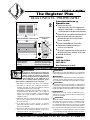
Features
&
Benefits
■
Thermal Safeguard:
•
High temperature manual reset:
turns off heater if normal operating
temperatures are exceeded
■
Commercial grade steel element
■
Powder coat paint process eliminates
sharp cutting edges
■
Five year extended warranty
■
Wall can designed for ease of
installation
■
Optional double pole field mount
thermostat kit available
■
Factory tested
MODELS:
RM202 RM208 RM108
RM151 RM162
Note: Thermostat not included
Dimensions in
inches (cm)
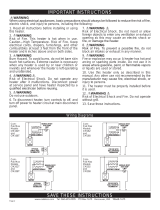
WARNING
Turn the electrical power off at the electrical
panel board (circuit breaker or fuse box) and lock
or tag the panel board door to prevent someone
from turning on power while you are working on
the heater. Failure to do so could result in serious
electrical shock, burns, or possible death.
SAVE THESE INSTRUCTIONS
1. Read all instructions before using this heater.
2. Read all information labels. Verify that the electrical supply
wires are the same voltage as the heater.
3. All electrical work and materials must comply with the
National Electric Code (NEC), the Occupational Safety and
Health Act (OSHA), and all state and local codes.
4. Connect the grounding pigtail (copper wire) provided in the
wall can to the supply ground wire.
5. If you need to install a new circuit or need additional wiring
information, consult a qualified electrician.
6. Protect electrical supply from kinks, sharp objects, oil,
grease, hot surfaces or chemicals.
7. WARNING
Overheating or fire may occur. DO NOT install the heater in a
floor, ceiling or behind doors.
8. WARNING
Fire or explosion may occur. DO NOT install heater in any
area where combustible vapors, gases, liquids, or excessive
lint or dust are present.
9. WARNING
Burn Hazard. This heater is hot when in use. To avoid
burns, do not let bare skin touch hot surfaces. Use extreme
caution when any heater is used by or near children or
invalids.
10. WARNING
Risk of Electrical Shock. Connect grounding lead to grounding
wire provided. Keep all foreign objects out of heater.
11. WARNING
Risk of Fire. Do not block heater. Heater must be kept clear of
all obstructions: a minimum of 3 feet in front, 6 inches
above and on both sides. Heaters must be kept clean of lint,
dirt and debris. (See Maintenance Instructions).
12. Use this heater only as described in this manual. Any
other use not recommended by the manufacturer may
cause fire, electrical shock, or injury to persons.
IMPORTANT INSTRUCTIONS
Tools Required:
Phillips Screwdriver
Straight Screwdriver
Wire Strippers
Utility Knife
(4) 1½“ Wood Screws
(3) Insulated Wire Connectors
(1) Strain Relief Connector
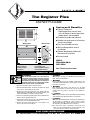
OWNER’S
GUIDE
The
Register
Plus
TEL: 360-693-2505 Fax: 360-694-8668 P.O. Box 1675 Vancouver, WA 98668-1675
Grill Front
Wall Can Front
4"T
10,16
2"T
5,08
3
/4"T
1,91
1"T
2,54
2
1
/2"T
6,35
3
3
/8"T
8,57
T
45˚
T
Wall Can Side
5
7
/8"T
14,92
1"T
2,54
2"T
5,08

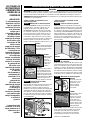
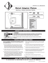
Installation
Instructions
PLACEMENT: For best results install The Register Plus on an inside wall. Headers and bracing are not
necessary. NOTE: The wall can must be installed in the TOP UP (horizontal) position only. Heater is not
approved for ceiling mount.
THERMOSTAT: A thermostat is required. A Cadet Elec tronic Thermostat is recommended for ultimate control
and comfort.
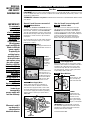
How do I install for new construction?
FIGURE 1
Metal legs position wall can
at minimum floor clearance.
The RM series REQUIRES A MINIMUM distance
of 6 inches from adjacent surfaces and 4½ inches
from the floor. However, Cadet RECOMMENDS
12 inches from all adjacent surfaces and 12 inches
from the floor (See Figure 5) for longer and cleaner
performance. Heaters must be spaced at least
3 feet apart.
Secure the wall can to the studs and/or sill plate
with screws through the larger (
3
/16 inch) holes.
(See Figures 1 and 2).
STEP 1
Mount Wall Can
How do I install in an existing wall?
Route supply wire from circuit breaker to
thermo stat to wall can. Remove a knockout
and attach the supply wire with a strain relief
connector leaving 10 inches wire lead for later
use. Connect supply ground wire to grounding
pigtail in wall can (See Figure 4). Proceed to
PART TWO.
STEP 2
Route Supply Wires
Route supply wire from circuit breaker to wall
thermo stat, then to wall can. Remove a knockout
and attach the supply wire with a strain relief
connector leaving 10 inches wire lead for later
use (See Figure 4). Connect sup ply ground wire
to ground ing pigtail in wall can.
FIGURE 6
Insert wall can, legs
first, into opening
and rotate into wall.
FIGURE 7
Keeping front of
wall can flush with
finished surface,
secure to wall stud
with screws through
larger (
3
/16 inch) holes.
IMPORTANT: Insert two drywall screws into
the small holes opposite the wall stud into the
drywall to rest against backside of sheetrock
(keeping wall can flush to wall).
Proceed to PART TWO.
FIGURE 2
Bend one leg
90 degrees
for higher
placement
and secure
to studs.
FIGURE 3
Face of wall can must
extend ½ inch or
5
/8
inch from face of stud
to allow for thickness
of sheetrock. Mount
wall can flush with
finished surface.
FIGURE 4
KNOCK-OUT
(TWIST TO
REMOVE)
STRAIN RELIEF
CONNECTOR
GROUNDING
PIGTAIL
GROUNDING
WIRE
SUPPLY
WIRE
WIRE
CONNECTOR
READ ALL
INSTRUCTIONS
AND SAFETY
INFORMATION
Part One
IMPORTANT!
It is extremely
important you
verify the
electrical supply
wires are the
same voltage as
the heater (i.e.
120 volt heater to
120 volt power
supply and 240 volt
heater to 240 volt
power supply).
If replacing an
existing heater,
check the labels
of the old heater
and replace using
the same voltage.
Hooking a 240 volt
heater to a 120 volt
power supply will
drastically reduce
the heater's
output. Hooking a
120 volt heater to a
240 volt power
supply will
destroy the heater.
Connecting your
heater to an
incompatible
power supply will
void the warranty.
Warranty is void if
any material is
sprayed on the
element or blower.
STEP 3
Mount Wall Can
STEP 2
Route Supply Wires
STEP 1
Cut Hole In Wall
FIGURE 5
Cut a hole 12¾ inches wide by 6 inches high
next to wall stud. The RM series REQUIRES A
MINIMUM distance of 6 inches from adjacent
surfaces and 4½ inches from the floor. However,
Cadet RECOMMENDS 12 inches from all adjacent
surfaces and 12 inches from the floor (See
Figure 5) for longer and cleaner performance.
Heaters must be spaced at least 3 feet apart.

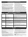
Element Wire Configuration (Multi-watt models RM151 or RM162 only)
Cadet’s Multi-Watt RM heater offers a variety of heat output options. You must first determine the
desired wattage and then configure the heating element wire connections. The heater is shipped from
the factory configured for 1600 Watts (240V) or 1200 Watts (208V) for RM162, and 1500 Watts (120V) for
RM151. If this is the wattage you desire, proceed to STEP 3.
On models RM151 and RM162, mark the wiring diagram on the back of the heater with the wattage used
for future reference.
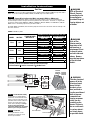
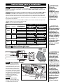
STEP 2
Installation
Instructions
Part Two
Fasten screw
Heater leads
Grounding
Pigtail
Blower wheel
Manual reset button
Supply leads
FIGURE 2
WARNING
Risk of Electrical
Shock. Connect
grounding lead to
grounding wire
provided. Keep all
foreign objects out
of heater.
WARNING
Risk of Fire.
Heater must be
kept clear of all
obstructions: a
minimum of 3 feet
in front; 6 inches
on both sides and
above. Heaters
must be kept clean
of lint, dirt and
debris.
WARNING
Turn the electrical
power off at the
electrical panel
board (circuit
breaker or fuse
box) and lock or
tag the panel board
door to prevent
someone from
turning on power
while you are
working on the
heater. Failure to
do so could result
in serious electri-
cal shock, burns,
or possible death.
If you are installing a Multi-Watt heater, model numbers RM151 or RM162, begin with STEP 2
below. If you are installing an RM202, RM208, or RM108, begin with STEP 3 below.
STEP 1
FIGURE 1 RM Wiring Table
Set the heater assembly (blower
wheel first) into the left side of the
wall can. Fasten at top with screw
provided. Unlace heater lead wires.
Connect the supply wires to the
heater wires (See Figure 2). Keep
all wires away from element
connections when wires are pushed
into free space on right of heater.
Secure grill with the screws
provided. Turn power on at the
electrical panel board.
STEP 3
STEP 4
Install Heater Assembly
Install Grill
MANUAL RESET
HIGH TEMP CUTOFF
VOLTAGEMODEL
240VRM162
208VRM162
IF YOUR DESIRED
WATTAGE IS:
1200
675
528
1600
900
700
YOUR WIRES WILL BE CONFIGURED LIKE THIS:
900W-240V
700W-240V
Upper Element A
675W-208V 525W-208V
Lower Element C
Yellow Terminal X
Yellow Terminal X
None (*)
Blue Terminal Z
None (*)
Yellow Terminal X
Blue Terminal Z
None (*)
Yellow Terminal X
Motor End View
Heater Element Locations
525W-208V
700W-240V
500W-120V
675W-208V
900W-240V
1000W-120V
Yellow Terminal X
Yellow Terminal X
None (*)
120VRM151
1500
1000
500
1000W-120V
500W-120V
Blue Terminal Z
None (*)
Yellow Terminal X
Yellow Terminal X
Yellow Terminal X
None (*)
*Cut Blue Terminal from Red Wire and wrap with electrical tape.
Yellow Terminal Y remains connected at B . Do Not Touch.

Operation
&
Maintenance
Warranty
How to operate your heater
1. Once installation is complete and power has been restored, turn the
thermostat knob fully clockwise.
2. When the room reaches your comfort level, turn the thermostat knob
counterclockwise until the heater turns off. The heater will automatically
cycle around this preset temperature.
3. To reduce the room temperature, turn the knob counterclockwise.
To increase the room temperature, turn the knob clockwise.
Maintenance As needed, or every six months, minimum.
1. WARNING! Before removing grill, turn the electrical power off at the
electrical panel board (circuit breaker or fuse box). Lock or tag the panel
board door to prevent someone from accidentally turning the power
on while you are working on the heater. Failure to do so could result
in serious electrical shock, burns, or possible death.
2. It is important that you verify power has been turned off and no power is going
to the heater before proceeding. Circuit breakers are often not marked correctly
and turning the wrong breaker off could mean electricity is flowing to the heater,
even if the heater does not appear to be working. If you are uncomfortable
working with electrical appliances, unable to follow these guidelines,
or do not have the necessary equipment, consult a qualified electrician.
3. Once you verify the power has been turned off correctly, proceed to the
next step.
4. Remove screws and take off grill.
5. Wash grill with hot soapy water and dry immediately.
6. While holding blower wheel (to avoid damage or bending), use a hair
dryer or vacuum on blow cycle to blow debris through the element
(Do not touch element).
7. Vacuum blower area without touching the elements.
8. Replace grill and secure with screws.
9. Turn thermostat to desired setting.
10. Turn power back on at the electrical panel board.
About the Manual Reset Temperature Limit Control
The heater is protected by a temperature-limiting control. The manual reset
temperature limit control is designed to open the heater circuit when excessive
operating temperatures are detected. The problem must be assessed and
the limit must be reset to resume operation.
Resetting the Manual Reset Temperature Limit Control
If the manual-reset limit control has opened the heater circuit due to excessive
operating temperatures, the heater will not work until the manual reset limit
button is pressed. After allowing the unit to cool for at least 10 minutes and
resolving the problem causing the limit to trip; use a narrow object such as
a ball-point pen to access the manual reset button through the lower-right
center section of the heater grill. Press FIRMLY and be sure to listen and feel
for a click, indicating it has been reset.
CONSULT LOCAL ELECTRICAL CODES TO DETERMINE WHAT WORK MUST BE PERFORMED BY QUALIFIED ELECTRICAL SERVICE PERSONNEL
Symptom Problem Solution
Breaker trips immediately
upon energizing heater.
Heater fan operates, but
does not discharge warm air.
Heater will not shut off.
Heater discharges smoke
or emits a burnt odor.
Element heats for a moment
without the fan turning, then
immediately stops heating.
Heater does not run.
Heater continually trips the
manual reset temperature
limit control.
Troubleshooting Chart
1.Incorrect supply voltage.
2.Overloaded circuit.
3.A short circuit exists in the supply or heater wiring.
4.Defective circuit breaker.
1.Insufficient element temperature.
2.Incorrect supply voltage.
3.Element has failed.
1. Heat loss from room is greater than heater capacity.
2.Defective thermostat.
3.Thermostat wired incorrectly to heater.
1.Dust, lint or other matter has accumulated
inside heater.
1.Defective motor or internal connection.
2.Fan or motor jammed.
1.Thermostat set too low.
2.Heater has tripped the manual reset temperature
limit control.
3.Power not on at the circuit breaker.
4.Broken or poorly connected wire(s) to heater.
5.Defective thermostat.
1. Dust, lint or other matter has accumulated
inside heater.
2. Airflow is blocked.
3. Fan or motor is jammed.
4. None of the above.
1. Verify that supply voltage matches the heater rating.
2. The total amperage of all heaters on a branch circuit must not be more than 80% of the
amperage rating of the circuit breaker and supply wire ratings. Use a lower wattage heater,
or reduce the number of heaters on the circuit.
3. Shorted supply or heater wires may be accompanied by severe sparking. Inspect all supply
and heater wiring insulation for damage. Do not reset the circuit breaker until all electrical
shorts have been repaired.
4. Replace the circuit breaker.
1. Allow a few moments for element to reach operating temperature.
2. Verify that supply voltage matches the heater rating.
3. Replace element.
1. Close doors and windows. Provide additional insulation or install a higher-wattage heater
or multiple heaters if necessary (if your circuit is rated for more capacity).
2. Adjust thermostat to its lowest setting. If heater continues to run (allow two minutes for the
thermostat to respond), and room temperature is greater than 50 degrees; replace thermostat.
3. Refer to thermostat documentation and correct wiring.
1. Clean heater (see “Operation & Maintenance” section for instructions).
1. Heater or fan motor requires replacement.
2. Remove obstruction, and press heater manual reset button (see “Operation & Maintenance”
section for instructions).
1. Adjust thermostat to a higher temperature until heater operates (see Problem #6 if the
problem persists).
2. Press the manual reset button (see “Operation & Maintenance” section for instructions).
3. Turn on the correct circuit breaker in the main panel.
4. Turn off power at circuit breaker. Check supply wire continuity and proper connection
to heater wires.
5. The entire heater, or any of its components may be checked for continuity to determine
the cause of any problem. Repair or replace the heater.
1. Clean heater (see “Operation & Maintenance” section for instructions.)
2. Remove obstruction. Maintain a minimum distance of 6 inches from adjacent surfaces, 4.5 inches
from the floor, and 3 feet for furniture or other objects placed directly in front of the heater.
3. Remove obstruction, and press heater manual reset button (see “Operation & Maintenance”
section for instructions).
4. Replace heater assembly .
©2009 Cadet Manufacturing Co. Printed in U.S.A. Rev. 6/09 #720104
7. IN THE EVENT CADET ELECTS TO REPLACE ANY PART OF YOUR CADET PRODUCT, THE
REPLACEMENT PARTS ARE SUBJECT TO THE SAME WARRANTIES AS THE PRODUCT.
THE INSTALLATION OF REPLACEMENT PARTS DOES NOT MODIFY OR EXTEND THE
UNDERLYING WARRANTIES. REPLACEMENT OR REPAIR OF ANY CADET PRODUCT OR
PART DOES NOT CREATE ANY NEW WARRANTIES.
8. These warranties give you specific legal rights, and you may also have other rights
which vary from state to state. Cadet neither assumes, nor authorizes anyone to
assume for it, any other obligation or liability in connection with its products other than
as set out herein.
If you believe your Cadet product is defective, please contact Cadet Manufacturing Co. at
360-693-2505, during the warranty period, for instructions on how to have the repair or
replacement processed. Warranty claims made after the warranty period has expired will
be denied. Products returned without authorization will be refused.
Parts and Service
Visit http://support.cadetco.com for information on where to obtain parts and service.
Maintenance: For more effective and safer operation and to prolong the life of the heater, read
the Owner’s Guide and follow the maintenance instructions included with each heater.
Failure to properly maintain the heater will void any warranty and may cause the heater to
function improperly. Warranties are non transferable and apply to original consumer only.
Warranty terms are set out below.
LIMITED ONE-YEAR WARRANTY: Cadet will repair or replace any Cadet product, including
thermostats, found to be defective within one year after the date of purchase.
Extended Product Warranty
LIMITED FIVE-YEAR WARRANTY: Cadet will repair or replace any Register Plus (RM)
series element or motor found to be defective or malfunctioning from first date of purchase
through the fifth year.
THESE WARRANTIES DO NOT APPLY:
1. Damage occurs to the product through improper installation or incorrect supply voltage;
2. Damage occurs to the product through improper maintenance, misuse, abuse, acci-
dent, or alteration;
3. The product is serviced by anyone other than Cadet.
4. If the date of manufacture of the product cannot be determined;
5. If the product is damaged during shipping through no fault of Cadet.
6. CADET’S WARRANTY IS LIMITED TO REPAIR OR REPLACEMENT AS SET OUT HEREIN.
CADET SHALL NOT BE LIABLE FOR DAMAGES SUCH AS PROPERTY DAMAGE OR FOR
CONSEQUENTIAL DAMAGES AND/OR INCIDENTAL EXPENSES RESULTING FROM
BREACH OF THESE WRITTEN WARRANTIES OR ANY EXPRESS OR IMPLIED WARRANTY.
Reduce-Reuse-Recycle
This product is made primarily of recyclable materials. You can reduce
your carbon footprint by recycling this product at the end of its useful life.
Contact your local recycling support center for further recycling instructions.
Page is loading ...
Page is loading ...
Page is loading ...
Page is loading ...
-
 1
1
-
 2
2
-
 3
3
-
 4
4
-
 5
5
-
 6
6
-
 7
7
-
 8
8


Cadet Manufacturing 00307 User manual
- Category
- Space heaters
- Type
- User manual
Ask a question and I''ll find the answer in the document
Finding information in a document is now easier with AI
in other languages
Related papers


Other documents
-
Cadet CGH562 User manual
-
-
-
-
-
Cadet CE163TW Owner's manual
-
Cadet CSTC402TA Installation guide
-
-
-