
WT150
3
/
8
”/12V
Cordless Drill/Drivers ENG
Perceuses/Tournevis Sans Cordon F
Taladros/Destornilladores Inalámbricos ES
Pag 02
Pag 16
Pag 30
NA-WT150-M-050727.indd 1 2005-7-27 17:52:54

Cordless Drill/Drivers WT150
SAFETY INSTRUCTIONS
WARNING! Read and understand all instructions. Failure to follow all instructions
listed below, may result in electric shock, fire and/or serious personal injury.
SAVE THESE INSTRUCTIONS
1. WORK AREA
a) Keep your work area clean and well lit. Cluttered benches and dark areas invite ac-
cidents.
b) Do not operate power tools in explosive atmospheres, such as in the presence
of flammable liquids, gases or dusts. Power tools create sparks which may ignite the
dust or fumes.
c) Keep by-standers, children, and visitors away while operating a power tool. Dis-
tractions can cause you to lose control.
2. ELECTRICAL SAFETY
a) A battery operated tool with integral batteries or a separate battery pack must
be recharged only with the specified charger for the battery. A charger that may be
suitable for one type of battery may create a risk of fire when used with another battery.
b) Use battery operated tool only with specifically designated battery pack. Use of
any other batteries may create a risk of fire.
3. PERSONAL SAFETY
a) Stay alert, watch what you are doing and use common sense when operating a
power tool. Do not use tool while tired or under the influence of drugs, alcohol,
or medication. A moment of inattention while operating power tools may result in seri-
ous personal injury.
b) Dress properly. Do not wear loose clothing or jewelry. Contain long hair. Keep
your hair, clothing, and gloves away from moving parts. Loose clothes, jewelry, or
long hair can be caught in moving parts. Keep handles dry, clean and free from oil and
grease. Rubber gloves and non-skid footwear are recommended when working outdoors.
c) Avoid accidental starting. Be sure switch is in the locked or “OFF” position be-
fore inserting battery pack. Carrying tools with your finger on the switch or inserting
the battery pack into a tool with the switch “ON” invites accidents.
d) Remove all adjusting keys and wrenches. Make a habit of checking that adjusting
keys, wrenches, etc. are removed from the tool before turning it “ON”.
e) Do not overreach. Keep proper footing and balance at all times. Proper footing and
balance enable better control of the tool in unexpected situations.
f) Use safety equipment. Always wear eye protection. Dust mask, non-skid safety
shoes, hard hat, or hearing protection may be used for appropriate conditions.
g) Keep hands away from all cutting edges and moving parts.
h) If devices are provided for the connection of dust extraction and collection
facilities, ensure these are connected and properly used. Use of these devices can
reduce dust-related hazards.
4. TOOL USE AND CARE
a) Use clamps or other practical way to secure and support the work-piece to a
stable platform. Holding the work by hand or against your body is unstable and may lead
to loss of control.
b) Do not force tool. Use the correct tool for your application. The correct tool will
0302
NA-WT150-M-050727.indd 2 2005-7-27 17:52:54

Cordless Drill/Drivers WT150
do the job better and safer at the rate for which it is designed. Excessive force only causes
operator fatigue, increased wear and reduced control.
c) Do not use tool if switch does not turn it “ON” or “OFF”. A tool that cannot be
controlled with the switch is dangerous and must be repaired.
d) Disconnect battery pack from tool or place the switch in the “LOCKED” or “OFF”
position before making any adjustments, changing accessories, or storing the
tool. Such preventive safety measures reduce the risk of starting the tool accidentally.
e) Store idle tools out of reach of children and other untrained persons. Tools are
dangerous in the hands of untrained users.
f) When battery pack is not in use, keep it away from other metal objects like: pa-
per clips, coins, keys, nails, screws, or other small metal objects that can make
a connection from one terminal to another. Shorting the battery terminals together
may cause sparks, burns, or a fire.
g) Maintain tools with care. Keep cutting tools sharp and clean. Properly maintained
tools, with sharp cutting edges, are less likely to bind and easier to control.
h) Check for misalignment or binding of moving parts, breakage of parts, and any
other condition that may affect the tool’s operation. If damaged, have the tool ser-
viced before using. Many accidents are caused by poorly maintained tools.
i) Use only accessories that are recommended by the manufacturer for your mod-
el. Accessories that may be suitable for one tool may create a risk of injury when used on
another tool.
j) Use the right tool. Do not force the tool or attachment to do a job for which it was not
designed.
5. SERVICE
a) Tool service must be performed only by qualified repair personnel. Service or
maintenance performed by unqualified personnel could result in a risk of injury.
b) When servicing a tool, use only identical replacement parts. Follow instructions
in the Maintenance section of this manual. Use of unauthorized parts or failure to
follow Maintenance Instructions may create a risk of electric shock or injury.
ADDITIONAL SAFETY RULES - FOR CORDLESS DRILLS
WARNING! Failure to follow these rules may result in serious personal injury.
1) Hold tool by insulated gripping surfaces when performing an operation where the
cutting tools may contact hidden wiring or its own cord. Contact with a “live” wire will
make exposed metal parts of the tool “live” and shock the operator.
2) Use auxiliary handles supplied with the tool. Loss of control can cause personal injury.
3) Wear ear protectors with impact (hammer) drills. Exposure to noise can cause hearing
loss.
4) Be aware that this tool is always in an operating condition because it does not have
to be plugged into an electrical outlet.
5) Always hold the tool with both hands. If the bit jams, two hands will give you maximum
control over torque reaction or kickback.
6) Disconnect battery pack from the tool or place switch in the “LOCKED” or “OFF”
position before making any assembly, adjustments or changing accessories. Such
preventive safety measures reduce the risk of starting the tool accidentally.
7) Secure material before cutting. Never hold it in your hand or across your legs.
8) Always wear eye protectors when using tool. Use a dust mask or respirator for ap-
0302
NA-WT150-M-050727.indd 3 2005-7-27 17:52:55

Cordless Drill/Drivers WT150
plications which generate dust.
9) Always check walls and ceiling to avoid hidden power cables and pipes.
10) Use clamps or a vise to hold work-piece whenever possible.
11) Save these instructions. Refer to them frequently and use them to instruct others who may
use this tool. If someone borrows this tool, make sure they have these instructions.
WARNING! Some dust created by power sanding, sawing, grinding, drilling and
other construction activities contains chemicals known to cause cancer, birth
defects or other reproductive harm. Some examples of these chemical are:
• Lead from lead-based paint
• Crystalline silica from bricks and cement and other masonry products
• Arsenic and chromium from chemically-treated lumber
Your risk to these exposures varies, depending on how often you do this type of work. To reduce
your exposure to these chemicals:
• Work in a well ventilated area
• Work with approved safety equipment, such as those dust masks that are specifically designed
to filter out microscopic particles.
BATTERY / CHARGER
1. Do not dispose of batteries in fire, or with household waste. Return exhausted batter-
ies to your local collection or recycling point.
2. Before using battery charger, read all instructions and cautionary markings on (1)
battery charger, (2) battery pack, and (3) product using battery.
3. CAUTION: To reduce the risk of injury, a WORX charger should only be used to
charge a WORX battery pack. Other types of batteries may burst causing personal injury
and damage. Do not charge a WORX battery pack with any other charger.
4. Do not store the battery pack in temperatures over +102ºF (39ºC).
5. Always charge the battery pack between temperatures 36ºF to 95ºF (2ºC to 35 ºC).
Ideal charging temperature is 65ºF to 84ºF (18ºC to 29ºC).
6. Avoid short circuit of the battery pack connections (screws & nails).
7. Charger is double insulated for additional electrical safety.
8. Do not expose charger to rain or water.
9. Charger is for indoor use only.
10. Do not incinerate or burn the battery pack, it may explode.
11. Do not charge a damaged battery pack.
12. Do not charge non-rechargeable batteries.
13. Replace any damaged power supply cords on your charger.
14. Always disconnect the charger power supply before making or breaking the con-
nections to the battery pack.
15. Battery pack and charger will be warm during charging, this is normal.
16. When not in use, remove a charged battery pack from the charger.
17. Always remove the battery pack from the charger immediately after re-charging is
completed.
WARNING: A small amount of electrolyte could leak from the battery pack under extremes
of temperature or after heavy use. Avoid contact with skin and eyes. Wash off immediately
from your skin and hands using clean water. For eye contact, rinse thoroughly with clean water
and seek medical treatment immediately.
0504
NA-WT150-M-050727.indd 4 2005-7-27 17:52:55

Cordless Drill/Drivers WT150
0504
The label on your tool may include the following symbols:
V...................................................................................................................................................................Volts
A..................................................................................................................................................................Amps
Hz.................................................................................................................................................................Hertz
~..........................................................................................................................................Alternating current
n
o
...............................................................................................................................................No load speed
......................................................................................................Class II construction / Double insulation
SYMBOLS
Read the manual
Warning
Wear safety goggles, dust mask
and ear protection
Use inside only
Double insulation
Do not expose to rain or water
Do not burn
NA-WT150-M-050727.indd 5 2005-7-27 17:52:56

Cordless Drill/Drivers WT150
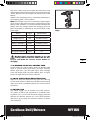
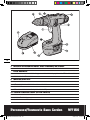
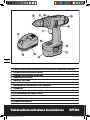
1. ON/OFF SWITCH WITH VARIABLE SPEED CONTROL
2. FORWARD/REVERSE/TRIGGER-LOCK BUTTON
3. HI/LOW GEAR CONTROL
4. ADJUSTABLE CLUTCH
5. KEYLESS CHUCK
6. BATTERY PACK
7. BATTERY PACK RELEASE LATCH
8. CHARGER
9. CHARGED INDICATOR LIGHT (GREEN)
10. CHARGING INDICATOR LIGHT (RED)
11. SCREW DRIVER BIT
12. BUBBLE LEVEL
13. MAGNETIC TRAY
0706
NA-WT150-M-050727.indd 6 2005-7-27 17:52:57

Cordless Drill/Drivers WT150
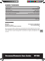
TECHNICAL DATA
Voltage Rating: 12V
No Load Speed: 0-350/0-1,200rpm
Chuck Capacity: 3/8”(10mm)
Maximum Torque (In Drill Mode): 265 in-lbs
Clutch Settings: 24 (incl. drill mode)
Maximum Drilling Capacity:
Wood: 1”(25mm)
Steel: 3/8”(10mm)
Machine Weight: 4.0lbs (1.8Kg)
ACCESSORIES
Batteries two (2) 12V - 2.0Ah Ni-Cd
1-hour charger voltage 120V-60Hz 1pc
Double-ended screw driver bit 2pcs
We recommend that you purchase your accessories from the same store that sold you the tool.
Use good quality accessories marked with a well-known brand name. Choose the type according
to the work you intend to undertake. Refer to the accessory packaging for further details. Store
personnel can assist you and offer advice.
0706
NA-WT150-M-050727.indd 7 2005-7-27 17:52:58

Cordless Drill/Drivers WT150
OPERATING INSTRUCTIONS
NOTE: Before using the tool, read the instruction
book carefully.
1. BEFORE USING YOUR CORDLESS DRILL
Your battery pack is UNCHARGED and you must
charge once before use. Your battery pack will not be
fully charged until you have performed several charge
and discharge operations by charging & working with
your drill. After this your battery pack performance will
improve.
Warning: The charger and battery pack are specif-
ically designed to work together so do not attempt
to use any other devices. Never insert or allow metallic
objects into your charger or battery pack connections be-
cause an electrical failure and hazard will occur.
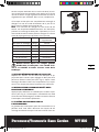
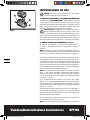
2. HOW TO CHARGE YOUR BATTERY PACK (See
Fig 1)
1) Connect the battery charger to the power supply. The
red light will illuminate for 3 seconds and then it will go
out.
Note: If the red light flashes at a rapid rate (approx. 5
flashes per second), this means that the charger has
failed and must be replaced.
2) Fully insert the battery pack into the charger. With
a normal charging process, only the red light will illu-
minate to show charging has started. The red light will
remain on during the charging process. A discharged
battery at normal ambient temperature will take approx-
imately 1 hour to reach full charge.
Note: If the battery temperature is lower than 36ºF (0ºC),
the green light will flash slowly (approximately 2 flashes
per second). Remove the battery and allow the battery
to warm-up to a charging temperature between 36ºF to
95ºF (2ºC and 35ºC).
If the battery temperature is over 140ºF (60ºC), the green
light will flash rapidly (approximately 5 flashes per sec-
ond). Remove the battery and allow the battery to cool-
down to a charging temperature between 36ºF to 95ºF
(2ºC and 35ºC).
If the battery temperature is over 176ºF (80ºC), the charg-
ing process will be stopped, and the red light will flash
with a low speed (approximately 2 flashes per second).
The battery must be replaced.
3) When the charging is complete, only the green light
will illuminate.
Note: When the battery is under charging and its volt-
age cannot reach 4V in 2 minutes, we consider the bat-
0908
Fig 1
NA-WT150-M-050727.indd 8 2005-7-27 17:52:59

Cordless Drill/Drivers WT150
tery to be “dead”, and the red light will flash with a low
speed (approximately 2 flashes per second). Remove the
“dead” battery from the charger and replace with a new
battery.
4) When the charging process is finished, the battery is
still charging with a current 50mA.
Note: The charger timer-circuit and battery pack temper-
ature safety-cutout device prevents overcharging of the
battery pack. However, it is recommended to remove the
battery from the charger when the charging cycle has
been completed as indicated by the illumination of the
green light.
Warning: After extended periods of use, the
battery will become hot. Allow the hot bat-
tery to cool down for at least 1 hour before re-
charging.
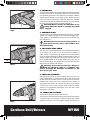
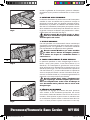
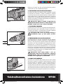
3. TO REMOVE OR INSTALL BATTERY PACK
Locate latches on side of battery pack and depress both
sides to release battery pack from your drill. Remove
battery pack from your drill (See Fig 2). After recharge
insert the battery pack into drill’s battery port. A simple
push and slight pressure will be sufficient.
4. ON/OFF SWITCH WITH BRAKE FUNCTION
Depress to start and release to stop your drill (See Fig
3). The on/off switch is fitted with a brake function which
stops your chuck immediately when you quickly release
the switch.
5. SWITCH LOCK
The switch trigger can be locked in the OFF position.
This helps to reduce the possibility of accidental start-
ing when not in use. To lock the switch trigger, place the
direction of rotation selector (2) in the center position
(See Fig 3) by pushing the direction buttons on either
side of the drill.
Fig 2
0908
Status Light ON/OFF/Flash
Battery charging red on
Charger failure red fast flash (5/sec)
Battery <32ºF (0ºC) green slow flash (2/sec)
Battery + 140ºF (60ºC) green fast flash (5/sec)
Battery + 176ºF (80ºC) red slow flash (2/sec)
Battery dead red slow flash (2/sec)
Charging complete green on
NA-WT150-M-050727.indd 9 2005-7-27 17:53:00

Cordless Drill/Drivers WT150
6. REVERSIBLE
The direction selector (2) located above the switch trigger
controls the direction of rotation. With the drill held in nor-
mal operating position, the direction of rotation selector
should be positioned to the right of the switch for drill-
ing. The rotation direction is reversed when the selector
is positioned to the left. When the selector is in the center
position, the trigger switch is locked (See Fig 3).
Warning: Never change the direction of ro-
tation when the chuck is rotating, wait until
it has stopped.
7. VARIABLE SPEED
This tool has a variable speed switch that delivers higher
speed and higher torque with increased trigger pres-
sure. Speed is controlled by the amount of switch trig-
ger depression.
Warning: Do not operate for long periods at
low speed because excess heat will be pro-
duced internally.
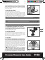
8. TWO-SPEED GEAR TRAIN
The drill has a two-speed gear train designed for drilling
or driving at LO (mark is 1) or HI (mark is 2) speeds. A
slide switch is located on top of the drill to select either
LO or HI speed (See Fig 4). When using the drill in the LO
speed range, the speed will decrease and the drill will
have greater power and torque. When using the drill in
the HI speed range, the speed will increase and the drill
will have less power and torque.
Warning: To prevent gear damage, always al-
low the chuck to come to a complete stop
before changing the direction of rotation or the
two-speed gear train.
9. CHUCK ADJUSTMENT.
Adjusting the chuck on your cordless drill is easy as it
comes fitted with a spindle lock. To open the chuck jaws
rotate the front section of the chuck. Insert the drill bit
between the chuck jaws and rotate the front section in
the opposite direction. Ensure the drill bit is in the center
of the chuck jaws. Finally, firmly rotate the front chuck
section in the opposite directions. Your drill bit is now
clamped in the chuck.
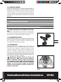
10. TORQUE ADJUSTMENT
(Screw driving force of your drill driver)
The torque is adjusted by rotating the torque adjustment
ring (See Fig 5). The torque is greater when the torque
adjustment ring is set on a higher setting. The torque is
1110
Fig 5
Fig 3
Fig 4
NA-WT150-M-050727.indd 10 2005-7-27 17:53:02

Cordless Drill/Drivers WT150
less when the torque adjustment ring is set on a lower
setting. Rotate the adjustment ring to the desired set-
ting:
11. BIT STORAGE
The bits provided with the drill can be placed in the stor-
age area located at the side of the drill, and slide in and
out (See Fig 6).
12. LEVEL DRILLING
The level indicator (12) is recessed in the motor hous-
ing on the top of the drill-driver. It can be used to keep
the drill level during horizontal drilling operation (See
Fig 7).
13. DRILLING
When drilling hard smooth surfaces, use a center punch
to mark the desired hole location. This will prevent the
drill bit from slipping off center as the hole is started.
Hold the tool fi rmly and place the tip of the bit at the
point to be drilled. Depress the switch trigger to start the
tool. Move the drill bit into the work-piece, applying only
enough pressure to keep the bit cutting. Do not force or
apply side pressure to elongate a hole.
Warning: Tungsten carbide drill bits should
always be used for concrete and masonry.
When drilling in metal, only use HSS drill bits in
good condition. Always use a magnetic bit holder
when using short screwdriver bits. When screw-
driving, apply a small quantity of liquid soap or
similar to the screw threads to ease insertion.
14. AUTOMATIC SPINDLE LOCK
The automatic spindle lock allows you to use as a regu-
lar screwdriver. You can give an extra twist to fi rmly
tighten a screw, loosen a very tight screw or continue
working when the battery energy has expired (See Fig
8). For manual screwdriver purposes, the chuck is auto-
matically locked when the tool is off.
Fig 6
Fig 7
1110
1 - 4 for driving small screws
5 - 9 for driving screws into soft material
10 - 14 for driving screws into soft and hard material
15 - 19 for driving screws into hard wood
20 - 23 for driving larger screws
24 for heavy drilling
Fig 8
NA-WT150-M-050727.indd 11 2005-7-27 17:53:07

Cordless Drill/Drivers WT150
15. DISPOSAL OF AN EXHAUSTED BATTERY PACK
To preserve natural resources, please recycle or
dispose of the battery pack properly. This battery
pack contains nickel-cadmium batteries. Consult your lo-
cal waste authority for information regarding available
recycling and/or disposal options. Discharge your bat-
tery pack by operating your drill, then remove the bat-
tery pack from the drill housing and cover the battery
pack connections with heavy duty adhesive tape to pre-
vent short circuit and energy discharge. Do not attempt
to open or remove any of the components.
WORKING HINTS FOR YOUR DRILL
1. WHY DOES THE DRILL NOT TURN ON WHEN
YOU PRESS THE SWITCH?
The forward and reverse switch, which is on top of the
trigger, is positioned in the lock function. Unlock the for-
ward and reverse switch putting it into the required rota-
tion position. Push the trigger and the drill will start to
rotate (See Fig 3).
2. THE DRILL ROTATES SLOWLY. WHY?
Verify the battery is fully charged by pressing the battery
test button. If the battery is not fully charged, recharge
the battery with the supplied battery charger (Note: Do
not charge the battery with a different charger. Charge
battery pack only with the charger provided).
3. THE DRILL STOPS BEFORE THE SCREW IS COM-
PLETELY TIGHTENED. WHY?
Verify the torque position of the torque adjusting ring,
you can find the torque adjusting ring between the chuck
and the drill body. Position 1 is the lowest torque (screw
driving force) and position 23 is the highest torque
(screw driving force). Position 24 is for drill operation.
Regulate the torque adjusting ring to a higher position
to reach the best result (See Fig 5).
4. I CANNOT FIT THE BATTERY INTO THE BAT-
TERY CHARGER. WHY?
The battery can be inserted into the charger only in one
direction. Turn the battery around until it can be inserted
into the slot, the red LED light should turn on when the
battery is charging (See Fig 1).
5. REASONS FOR DIFFERENT CHARGING TIMES.
Your charge time can be affected by many reasons, which
are not defects in your product. If the battery pack is only
partly discharged it may be re-charged in less than 1
1312
NA-WT150-M-050727.indd 12 2005-7-27 17:53:09

Cordless Drill/Drivers WT150
hour. If the battery pack and ambient temperature are
very cold then re-charging may take 1 to 1-1/2 hours. If
the battery pack is very hot it will not re-charge because
the internal temperature safety cutout will prevent it. If
the battery pack is very hot you must remove your bat-
tery pack from the charger and allow your battery pack
to cool first to ambient temperature and then recharging
can be started. If you charge a second battery pack im-
mediately after the first then the charger can be over-
heated. Always allow at least 15 minutes rest between
battery pack charging.
6. REASONS FOR DIFFERENT BATTERY PACK
WORKING TIMES.
Charging time issues, as above, and having not used a
battery pack for a prolonged time will reduce the work-
ing life of the battery pack. This can be corrected after
several charge and discharge operations by charging &
working with your drill. Heavy working conditions such
as large screws into hard wood will use up the battery
pack energy faster than lighter working conditions. Do
not re-charge your battery pack below 32
o
F (0
o
C) and
above 86
o
F (30
o
C) as this will affect performance.
MAINTAIN TOOLS WITH CARE
Keep tools sharp and clean for better and safer perfor-
mance. Follow instructions for lubricating and changing
accessories. Inspect tool cords periodically and if dam-
aged, have repaired by authorized service facility.
Your power tool requires no additional lubrication or
maintenance. There are no user serviceable parts in
your power tool. Never use water or chemical cleaners
to clean your power tool. Wipe clean with a dry cloth.
Always store your power tool in a dry place. Keep the
motor ventilation slots clean. Keep all working controls
free of dust. If you see some sparks flashing in the ven-
tilation slots, this is normal and will not damage your
power tool.
WARRANTY
LIMITED 60-DAY EXCHANGE POLICY
During the first 60 days after date of purchase, you may
exchange a tool which does not work properly due to
defects in materials or workmanship by returning the
power tool to the retailer where it was purchased. To
receive a replacement power tool, you must present a
dated proof of purchase and return all original equip-
1312
NA-WT150-M-050727.indd 13 2005-7-27 17:53:09

Cordless Drill/Drivers WT150
ment packaged with the original product.
LIMITED TWO YEAR WARRANTY
The manufacturer warrants that, for a period of 2 years
from the date of purchase, this product shall be free of
defects in materials and workmanship. We will repair
or replace, at our option, this tool during the warranty
period, and we may require that the tool be sent postage
prepaid to an approved service center with all original
equipment and a dated proof of purchase. Any replace-
ment or repaired power tool will only be covered by the
limited warranty for the balance of the warranty period
from the date of the original purchase.
WHAT IS NOT COVERED
This warranty applies only to the original purchaser at
retail and is not transferable.
This warranty does NOT cover service or replacement of
parts resulting from normal wear.
This warranty does NOT cover accessories or battery
packs.
This warranty does NOT cover malfunction, failure or
defects due to:
- abnormal use, abuse, neglect, or use not in accordance
with the operations manual
- damage resulting from accidents, drops or mishan-
dling of the tool
- alteration or repairs by other than approved service
centers
- commercial or rental use.
The manufacturer makes no warranties, representa-
tions or promises as to the quality or performance of its
power tools other than those specifically stated in this
warranty.
FOR SERVICE
Contact our toll-free consumer service line at 1-866-354-
WORX (9679) (Mon.- Sat. 9am to 9pm EST) to receive a
replacement tool or to be directed to an approved ser-
vice center. When you make a warranty claim or send
the tool for warranty service, you must also include a
dated proof of purchase.
ADDITIONAL LIMITATIONS
This warranty is only valid for products purchased and
used in the United States of America, its territories or
Canada. Any implied warranty granted under state law,
including warranties of merchantability or fitness for a
1514
NA-WT150-M-050727.indd 14 2005-7-27 17:53:10

Cordless Drill/Drivers WT150
1514
particular purpose, are limited to two years from the
date of purchase. The manufacturer is not responsible
for direct, indirect, incidental or consequential damages
including, but not limited to, liability for loss of income
arising from the purchase or use of the product. Some
states and provinces do not allow limitations on how
long an implied warranty lasts and/or do not allow the
exclusion or limitation of incidental damages, so the
above limitations and exclusions may not apply to you.
This warranty gives you specific legal rights, and you
may also have other rights which vary from state to state
or province to province.
The manufacturer declines any responsibility in regards
to civil liability arising from abusive use or not in confor-
mity with proper use and maintenance of the machine
as described in the operator’s manual.
After the purchase, the manufacturer recommends
proper maintenance of the machine and to read
the operator’s manual before using the machine.
NA-WT150-M-050727.indd 15 2005-7-27 17:53:10
Page is loading ...
Page is loading ...
Page is loading ...
Page is loading ...

Perceuses/Tournevis Sans Cordon WT150
1. INTERRUPTEUR MARCHE/ARRÊT AVEC COMMANDE DE VITESSE
2. BOUTON DE ROTATION DIRECTE/INVERSE ET DE DÉSAFFECTATION/VERROUILLAGE
DE LA GÂCHETTE
3. COMMANDE BASSE VITESSE (1) / HAUTE VITESSE (2) DE LA BOÎTE D¹ENGRENAGES
4. EMBRAYAGE RÉGLABLE
5. MANDRIN SANS CLÉ
6. BLOC-PILES
7. MÉCANISME DE RETENUE DU BLOC-PILES
8. CHARGEUR
9. TÉMOIN LUMINEUX VERT (PILE CHARGÉE)
10. TÉMOIN LUMINEUX ROUGE (PILE EN CHARGE)
11. EMBOUT DE TOURNEVIS
12. NIVEAU À BULLE
13. PLATEAU MAGNÉTIQUE
2120
NA-WT150-M-050727.indd 20 2005-7-27 17:53:14
Page is loading ...
Page is loading ...
Page is loading ...
Page is loading ...
Page is loading ...
Page is loading ...
Page is loading ...
Page is loading ...
Page is loading ...
Page is loading ...
Page is loading ...
Page is loading ...
Page is loading ...

Taladros/Destornilladores Inalámbricos WT150
1. GATILLO DE ENCENDIDO/APAGADO CON CONTROL DE VELOCIDAD VARIABLE
2. BOTÓN DE ADELANTE/ATRÁS/TRABA
3. CONTROL DE VELOCIDAD ALTA/BAJA
4. EMBRAGUE AJUSTABLE
5. MANDRIL SIN LLAVE
6. PAQUETE DE BATERIAS
7. LENGÜETAS DE LIBERACIÓN DE LAS BATERIAS
8. CARGADOR
9. LUZ INDICADORA DE CARGA COMPLETA (VERDE)
10. LUZ INDICADORA DE CARGA (ROJA)
11. BROCA DESTORNILLADORA
12. NIVEL DE BURBUJA
13. BANDEJA MAGNÉTICA
3534
NA-WT150-M-050727.indd 34 2005-7-27 17:53:29
Page is loading ...
Page is loading ...
Page is loading ...
Page is loading ...
Page is loading ...
Page is loading ...
Page is loading ...
Page is loading ...
Page is loading ...

Designed in Italy. Made in China
Conçu en Italie. Fabriqué en Chine
Diseñado en Italia. Fabricado en China
NA-WT150-M-050727.indd 44 2005-7-27 17:53:41
-
 1
1
-
 2
2
-
 3
3
-
 4
4
-
 5
5
-
 6
6
-
 7
7
-
 8
8
-
 9
9
-
 10
10
-
 11
11
-
 12
12
-
 13
13
-
 14
14
-
 15
15
-
 16
16
-
 17
17
-
 18
18
-
 19
19
-
 20
20
-
 21
21
-
 22
22
-
 23
23
-
 24
24
-
 25
25
-
 26
26
-
 27
27
-
 28
28
-
 29
29
-
 30
30
-
 31
31
-
 32
32
-
 33
33
-
 34
34
-
 35
35
-
 36
36
-
 37
37
-
 38
38
-
 39
39
-
 40
40
-
 41
41
-
 42
42
-
 43
43
-
 44
44


Ask a question and I''ll find the answer in the document
Finding information in a document is now easier with AI
in other languages
- français: Worx WT150 Manuel utilisateur
- español: Worx WT150 Manual de usuario
Related papers
-
Worx WX174L.9 Owner's manual
-
-
-
-
-
-
Worx WX065 Operating instructions
-
-
-
Other documents
-
Rockwell ShopSeries RS2212 User manual
-
Ferm CDM1138 User manual
-
Ryobi 5133000214 Datasheet
-
GYS BT-10323001-15 Owner's manual
-
Campbell Hausfeld DG201800CD User manual
-
Rockwell RK2511K2 Operating Instructions Manual
-
-
Kompernass X 18 V - MANUEL 2 Operating And Safety Instructions Manual
-
 WORX Tools Chainsaw WT525 User manual
-
Facom BSYS.BPMUSIC Owner's manual
