ADLINK Technology cPCI-6910 Series User manual
- Category
- Server/workstation motherboards
- Type
- User manual
This manual is also suitable for

Artisan Technology Group is your source for quality
new and certied-used/pre-owned equipment
• FAST SHIPPING AND
DELIVERY
• TENS OF THOUSANDS OF
IN-STOCK ITEMS
• EQUIPMENT DEMOS
• HUNDREDS OF
MANUFACTURERS
SUPPORTED
• LEASING/MONTHLY
RENTALS
• ITAR CERTIFIED
SECURE ASSET SOLUTIONS
SERVICE CENTER REPAIRS
Experienced engineers and technicians on staff
at our full-service, in-house repair center
WE BUY USED EQUIPMENT
Sell your excess, underutilized, and idle used equipment
We also offer credit for buy-backs and trade-ins
www.artisantg.com/WeBuyEquipment
REMOTE INSPECTION
Remotely inspect equipment before purchasing with
our interactive website at www.instraview.com
LOOKING FOR MORE INFORMATION?
Visit us on the web at www.artisantg.com for more
information on price quotations, drivers, technical
specications, manuals, and documentation
Contact us: (888) 88-SOURCE | sales@artisantg.com | www.artisantg.com
SM
View
Instra

Advance Technologies; Automate the World.
Manual Revison: 2.05
Revision Date: June 6, 2008
Part No: 50-15056-1030
cPCI-6910 Series
6U CompactPCI
®
Single Board Computer with
Dual-Core Intel
®
Xeon
®
Processor LV/ULV
User’s Manual

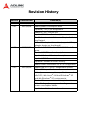
Revision History
Version Release Date Revision(s)
2.00 2006/12/29 First release.
2.01 2007/04/04 Added power consumption data.
Updated J1 to J5 pin assignment.
Added RJ-45 COM pin-out.
Updated SW1 function description.
Modified various installations in Chapter 5: Get-
ting Started.
Added CF adapter information (supports CF by
adapter design on front board).
2.02 2007/07/19 Modified cPCI-6910 with cPCI-R6910 Block Dia-
gram.
Updated SWZ2 function description.
Updated Onboard Devices descriptions.
Updated IPMI Sensor Lists.
Updated Firmware Revision History.
Added Switch information for RTM configuration.
2.03 2007/08/08 Added new cPCI-6910 Configuration options.
Added CPU specifications.
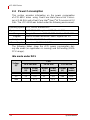
Added power consumption specifications under
idle DOS, idle Linux
®
, full-load WIndows
®
XP
and idle Windows
®
XP environments.
Revised Firmware revision history information.
Added Voltage, Amperage and wattage units on
power consumption tables.
Updated switch function information

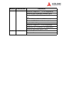
2.04 2008/02/25
Revised CompactPCI
®
J3 Pin Assignments
Revised Oem Command Summary Table
Revised BMR-AVR-cPCI Supported Command
List
Revised Onboard Device BIOS descriptions
Revised USB 2.0 Controller descriptions
Updated Block Diagram
Revised CompactPCI J2 Pin Assignments
Revised RJ-45 Connector Pin Assignments
Revised OemShowRevision Table
2.05 2008/06/06 Correct LAN status table
Correct address
Version Release Date Revision(s)

This page intentionally left blank.

Preface v
cPCI-6910 Series
Preface
Copyright 2008 ADLINK TECHNOLOGY INC.
This document contains proprietary information protected by copy-
right. All rights are reserved. No part of this manual may be repro-
duced by any mechanical, electronic, or other means in any form
without prior written permission of the manufacturer.
Disclaimer
The information in this document is subject to change without prior
notice in order to improve reliability, design, and function and does
not represent a commitment on the part of the manufacturer.
In no event will the manufacturer be liable for direct, indirect, spe-
cial, incidental, or consequential damages arising out of the use or
inability to use the product or documentation, even if advised of
the possibility of such damages.
Trademarks
Microsoft
®
, MS-DOS
®
, Windows
®
98, Windows
®
98 SE, Win-
dows
®
2000, Windows
®
XP, Windows
®
XP Professional, and Win-
dows
®
Server 2003 are registered trademarks of Microsoft
®
Corporation. Intel
®
Celeron
®
M, Xeon
®
, and SpeedStep
®
are reg-
istered trademarks of Intel
®
Corporation. CompactFlash
®
is a reg-
istered trademark of Sandisk
®
Corporation. Phoenix Award™
BIOS is a trademark of Phoenix
®
Technologies Inc. CompactPCI
®
and PICMG
®
are registered trademarks of the PCI Industrial Com-
puter Manufacturers Group. PCI Express
®
is a registered trade-
mark of the Peripheral Component Interconnect Special Interest
Group.
LSI
®
Logic is a registered trademark of LSI Corporation. Linux
®
is a registered trademark of Linus Torvalds. PLX FastLane
™
is a trade-
mark of PLX Technology, Inc. VxWorks
®
is a registered trademark
of Wind River.
Product names mentioned herein are used for identification pur-
poses only and may be trademarks and/or registered trademarks
of their respective companies.

vi Preface
cPCI-6910 Series
Using this Manual
Audience and Scope
The cPCI-6910 Series User’s Manual is intended for hardware
technicians and systems operators with knowledge of installing,
configuring and operating industrial grade single board computers.
Manual Organization
This manual is organized as follows:
Preface: Presents important copyright notifications,
disclaimers, trademarks, and associated information on the
proper understanding and usage of this document and its
associated product(s).
Chapter 1, Introduction: Introduces the cPCI-6910 Series, its
features, block diagrams, and package contents.
Chapter 2, Specifications: Presents information on cPCI-
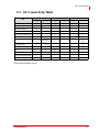
6910 Series blades, Rear Transition Modules, I/O connectivity
and power consumption.
Chapter 3, Functional Description: Provides detailed
information on supported processors, chipsets, memory, high
speed I/O, blade features and various functions.
Chapter 4, Jumpers and Connectors: Provides detailed
information on board layout, connector pin assignments,
switches, jumpers, etc.
Chapter 5, Getting Started: Describes installation of the blade
and rear transition module.
Chapter 6, Driver Installation: Explains how to install drivers
and the operating system environment for the cPCI-6910
Series.
Chapter 7, Watchdog Timer: This section explains the
operation of the cPCI-6910 Series watchdog timer (WDT).

Preface vii
cPCI-6910 Series
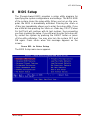
Chapter 8, BIOS Setup: Describes the setup utility program
for specifying cPCI-6910 Series system configurations and
settings.
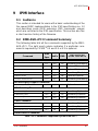
Chapter 9, IPMI Interface: Describes OEM extension IPMI
commands' usages which are not listed in the associated IPMI
specification documentation.
Appendix, Serial Console: Provides a detailed explanation of
how to setup and use a serial console for remote access to
POST messages and system commands.
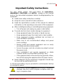
Important Safety Instructions: Presents saftety instructions
all users must follow for the proper setup, installation and
usage of equipment and/or software.
Warranty Information: Presents important warranty
information for users/manufacturers rights and responsibilities
regarding ADLINK products and services.

viii Preface
cPCI-6910 Series
Conventions
Take note of the following conventions used throughout this
manual to make sure that users perform certain tasks and
instructions properly..
NOTE:
NOTE:
Additional information, aids, and tips that help users per-
form tasks.
CAUTION:
Information to prevent minor physical injury, component
damage, data loss, and/or program corruption when try-
ing to complete a task.
WARNING:
Information to prevent serious physical injury, compo-
nent damage, data loss, and/or program corruption
when trying to complete a specific task.

Preface ix
cPCI-6910 Series
Getting Service
Contact us should you require any service or assistance.
ADLINK TECHNOLOGY INC. (HEADQUARTERS)
Web Site: http://www.adlinktech.com
Sales & Service: [email protected]
Telephone No.: +886-2-8226-5877
Fax No.: +886-2-8226-5717
Mailing Address: 9F No. 166 Jian Yi Road, Chungho City,
Taipei 235, Taiwan
ADLINK TECHNOLOGY AMERICA INC.
Sales & Service: [email protected]
Toll-Free: +1-866-423-5465
Fax No.: +1-949-727-2099
Mailing Address: 8900 Research Drive, Irvine,
CA 92618, USA
ADLINK TECHNOLOGY CO. LTD. (BEIJING)
Sales & Service: market@adlinkchina.com.cn
Telephone No.: +86-10-5885-8666
Fax No.: +86-10-5885-8625
Mailing Address: Rm. 801, Power Creative E,
No. 1, B/D Shang Di East Rd.
Beijing, 100085 China
ADLINK TECHNOLOGY CO. LTD. (SHANGHAI)
Sales & Service: market@adlinkchina.com.cn
Telephone No.: +86-21-6495-5210
Fax No.: +86-21-5450-0414
Mailing Address: 4F, Bldg. 39, No.333 Qinjiang Road,
Chao He Jing Hi Tech Park
Shanghai, 200233 China
ADLINK TECHNOLOGY CO. LTD. (SHENZHEN)
Sales & Service: market@adlinkchina.com.cn
Telephone No.: +86-755-2643-4858
Fax No.: +86-755-2664-6353
Mailing Address: 2F, C Block, Bld. A1,
Cyber-Tech Zone, Gao Xin Ave. Sec 7,
High-Tech Industrial Park S.,
Shenzhen, 518057 China

xPreface
cPCI-6910 Series
ADLINK TECHNOLOGY INC. (EUROPE)
Sales & Service: em[email protected]
Toll-Free: +49-211-495-5552
Fax No.: +49-211-495-5557
Mailing Address: Nord Carree 3, 40477
Düsseldorf, Germany
ADLINK TECHNOLOGY INC. (INDIA)
Sales & Service: [email protected]
Telephone No.: +91-80-6560-5817
Fax No.: +91-80-2244-3548
Mailing Address: No. 1357, Ground Floor, "Anupama",
Aurobindo Marg JP Nagar (Ph-1)
Bangalore, Karnataka 560078, India
ADLINK TECHNOLOGY JAPAN CORP.
Sales & Service japan@adlinktech.com
Telephone No. +81-3-4455-3722
Fax No. +81-3-5333-6040
Mailing Address Asahiseimei Hatagaya Bld. 1-1-2
Hatagaya Shibuya-ku, Tokyo, Japan
ADLINK TECHNOLOGY INC. (SOUTH KOREA)
Sales & Service: [email protected]
Telephone No.: +82-2-2057-0565
Fax No.: +82-2-2057-0563
Mailing Address: 4F, Kostech Building, 262-2,
Yahgjae-Dong, Seocho-Gu,
Seoul, 137-130, South Korea
ADLINK TECHNOLOGY SINGAPORE PTE. LTD.
Sales & Service: [email protected]
Telephone No.: +65-6844-2261
Fax No.: +65-6844-2263
Mailing Address: 84 Genting Lane #07-02A,
Cityneon Design Center,
Singapore 349584

Preface xi
cPCI-6910 Series
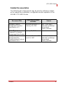
Related Documentation
The following list of documents may be used as reference materi-
als to support the installation, configuraiton and/or operation of the
ADLINK cPCI-6910 Series.
Document Title
Publication Number
and Date
Source
Intelligent Platform
Management Interface
Specification v1.5
Document Revision 1.1
February 20, 2002
Intel
®
Corp. http://
www.intel.com/design/
servers/ipmi/
license_ipmi.htm
PICMG
®
2.9 D1.0
CompactPCI
®
System
Management Specification
January 21, 2000
Intelligent Platform
Management Bus
Communications Protocol
Specification v0.9
Document Revision 0.15
June 24, 1997
Intel
®
Corp. http://
www.intel.com/design/
servers/ipmi/
license_ipmi.htm

xii Preface
cPCI-6910 Series
This page intentionally left blank.

Table of Contents xiii
cPCI-6910 Series
Table of Contents
Preface..................................................................................... v
Using this Manual ...........................................................vi
Conventions ..................................................................viii
Getting Service ...............................................................ix
Related Documentation ..................................................xi
Table of Contents................................................................. xiii
List of Figures...................................................................... xix
List of Tables........................................................................ xxi
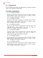
1 Introduction ........................................................................ 1
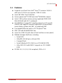
1.1 Features............................................................................... 3
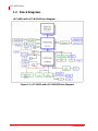
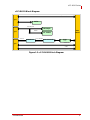
1.2 Block Diagrams.................................................................... 4
cPCI-6910 with cPCI-R6910 Block Diagram ..................4
cPCI-R6911 Block Diagram ............................................5
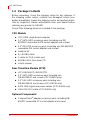
1.3 Product List.......................................................................... 6
cPCI-6910 Configurations ...............................................6
Rear Transition Modules .................................................7
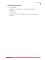
1.4 Package Contents ............................................................... 8
CPU Module ...................................................................8
Rear Transition Module (RTM) .......................................8
Optional Components .....................................................8
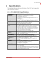
2 Specifications................................................................... 11
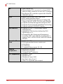
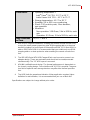
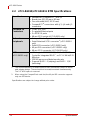
2.1 cPCI-6910 SBC Specifications.......................................... 11
2.2 cPCI-R6910/cPCI-R6911 RTM Specifications................... 14
2.3 I/O Connectivity Table ....................................................... 15
2.4 Power Consumption .......................................................... 16
Idle mode under DOS ...................................................16

xiv Table of Contents
cPCI-6910 Series
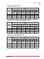
Idle mode under Linux® ................................................17
Full-load CPU mode under Windows® XP ...................17
Idle mode under Windows® XP ....................................17
3 Functional Description..................................................... 19
3.1 Processor........................................................................... 19
3.2 Chipset............................................................................... 19
3.3 Memory.............................................................................. 19
3.4 PCI Express® (High-speed Serial I/O) .............................. 21
3.5 Hub Interface 1.5 ............................................................... 21
3.6 Intel® 6300ESB I/O Controller Hub (ICH).......................... 22
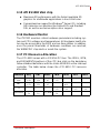
3.7 Ultra ATA100/66/33 IDE .................................................... 23
3.8 USB 2.0 ............................................................................. 23
3.9 LPC/Firmware Hub ............................................................ 23
3.10 System Management Bus.................................................. 23
3.11 UART................................................................................. 24
3.12 Watchdog Timer................................................................. 24
3.13 Real Time Clock................................................................. 24
3.14 PCI 32-bit and PCI-X Interface .......................................... 24
3.15 ATI ES1000 VGA chip ....................................................... 25
3.16 Hardware Monitor .............................................................. 25
3.17 PCI Resource Allocation.................................................... 25
3.18 PCI-X to PCI-X Bridge ....................................................... 26
4 Jumpers and Connectors................................................. 27
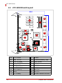
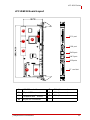
4.1 cPCI-6910 Board Layout.................................................... 28
4.2 cPCI-6910 Front Panel ...................................................... 29
System LED indication ..................................................29
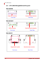
4.3 cPCI-6910 Daughterboard Layout..................................... 30
DB-6910IDE ..................................................................30
DB-6910SAT .................................................................30
DB-6910CF ...................................................................30

Table of Contents xv
cPCI-6910 Series
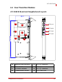
4.4 Rear Transition Modules.................................................... 31
cPCI-R6910 Board and Daughterboard Layouts ..........31
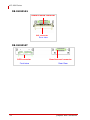
DB-R6910SAS ..............................................................32
DB-R6910SAT ..............................................................32
cPCI-R6911 Board Layout ............................................33
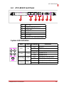
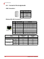
4.5 Connector Pin Assignments .............................................. 34
USB Connectors ...........................................................34
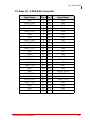
Ethernet (RJ-45) Connector ..........................................34
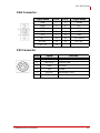
VGA Connector .............................................................35
PS2 Connector .............................................................35
Serial Port (COM1) .......................................................36
CompactFlash® Connector ..........................................37
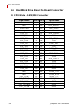
4.6 Hard Disk Drive Board to Board Connector....................... 38
On CPU Blade - SATA/IDE Connector .........................38
On Rear I/O - SATA/SAS Connector ............................39
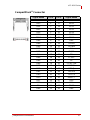
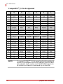
CompactPCI® J1 Pin Assignment ................................40
CompactPCI® J2 Pin Assignment ................................41
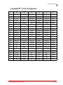
CompactPCI® J3 Pin Assignment ................................42
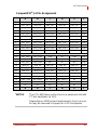
CompactPCI® J4 Pin Assignment ................................43
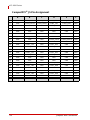
CompactPCI® J5 Pin Assignment ................................44
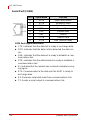
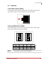
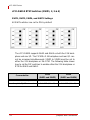
4.7 Switches ............................................................................ 45
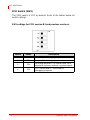
Clear CMOS Switch (SWZ1) ........................................45
COM and IPMI Switch (SWZ2) .....................................45
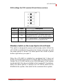
PCB Switch (SW1) ........................................................46
Miniature Switch on the Lower Ejector (Front Panel) ...47
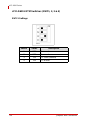
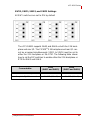
cPCI-R6911 RTM Switches (SWY1, 2, 3 & 4) ..............48
5 Getting Started ................................................................. 51
5.1 Tools.................................................................................. 51
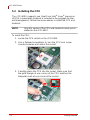
5.2 Installing the CPU.............................................................. 52
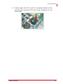
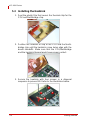
5.3 Installing the Heatsink........................................................ 54
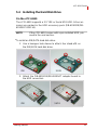
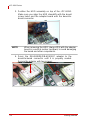
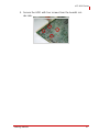
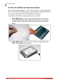
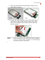
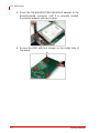
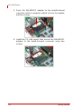
5.4 Installing the Hard Disk Drive ............................................ 55

xvi Table of Contents
cPCI-6910 Series
On the cPCI-6910 .........................................................55
On the cPCI-R6910 rear transition module ...................58
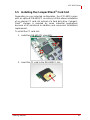
5.5 Installing the CompactFlash® Card Slot............................ 61
5.6 Installing the cPCI-6910 to the Chassis............................. 63
5.7 Installing the cPCI-R6910 to the Chassis .......................... 63
6 Driver Installation.............................................................. 65
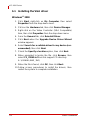
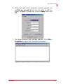
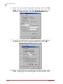
6.1 Installing the VGA driver.................................................... 66
Windows® 2000 ............................................................66
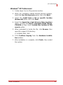
Windows® XP Professional ..........................................67
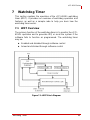
7 Watchdog Timer................................................................ 69
7.1 WDT Overview................................................................... 69
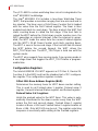
Configuration Registers ................................................70
GPIO Control Registers ................................................72
WDT Programming Procedure .....................................73
Utilities ..........................................................................74
7.2 Intel® Preboot Execution Environment (PXE) ................... 74
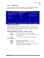
8 BIOS Setup........................................................................ 75
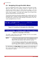
8.1 Navigating Through the BIOS Menus................................ 76
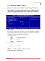
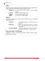
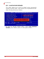
8.2 Standard CMOS Features ................................................. 77
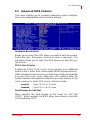
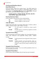
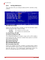
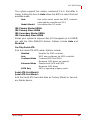
8.3 Advanced BIOS Features.................................................. 81
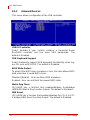
8.4 Advanced Chipset Features............................................... 85
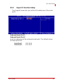
8.5 Integrated Peripherals........................................................ 87
8.6 PnP/PCI Configuration....................................................... 92
8.7 Frequency/Voltage Control................................................ 93
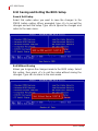
8.8 Load Fail-Safe Defaults ..................................................... 94
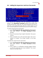
8.9 Setting the Supervisor and User Passwords ..................... 95
8.10 Saving and Exiting the BIOS Setup................................... 96
9 IPMI Interface..................................................................... 97
9.1 Audience............................................................................ 97

Table of Contents xvii
cPCI-6910 Series
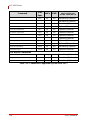
9.2 BMR-AVR-cPCI Command Summary ............................... 97
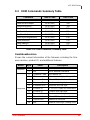
9.3 OEM Commands Summary Table..................................... 99
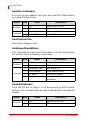
OemShowRevision .......................................................99
OemRescanGaInput ...................................................100
OemTestFunction .......................................................100
OemReportGeoAddress .............................................100
OemEnableSmbus ......................................................100
OemDisableSmbus .....................................................101
OemDispDebugVariable .............................................101
OemResetHost ...........................................................101
OemPowerOff .............................................................102
OemPowerOn .............................................................102
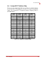
9.4 CompactPCI® Address Map............................................ 103
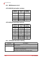
9.5 IPMI Sensors List............................................................. 104
cPCI-6910 B2 and earlier versions .............................104
cPCI-6910 B3 and future versions ..............................104
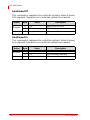
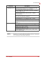
9.6 Firmware Revision History............................................... 104
9.7 Known Issues .................................................................. 106
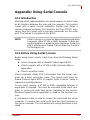
Appendix: Using Serial Console ....................................... 107
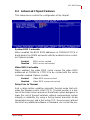
10.1 Introduction...................................................................... 107
10.2 Before Using Serial Console............................................ 107
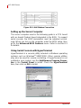
Setting up the Server Computer .................................108
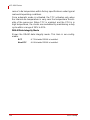
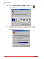
Using Serial Console with HyperTerminal ..................108
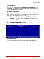
10.3 Performing Operations in the HyperTerminal Console.... 113
Important Safety Instructions............................................ 115
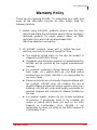
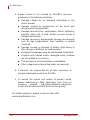
Warranty Policy................................................................... 117

xviii Table of Contents
cPCI-6910 Series
This page intentionally left blank.

List of Figures xix
cPCI-6910 Series
List of Figures
Figure 1-1: cPCI-6910 with cPCI-R6910 Block Diagram ...................4
Figure 1-2: cPCI-R6911 Block Diagram.............................................5
Figure 7-1: WDT Block Diagram......................................................69
Figure 8-1: Control keys & Information Bar in Main Menu...............76
Figure 8-2: Control keys in Sub-menu .............................................76
Figure 10-1: Null Modem Connection ..............................................108
Page is loading ...
Page is loading ...
Page is loading ...
Page is loading ...
Page is loading ...
Page is loading ...
Page is loading ...
Page is loading ...
Page is loading ...
Page is loading ...
Page is loading ...
Page is loading ...
Page is loading ...
Page is loading ...
Page is loading ...
Page is loading ...
Page is loading ...
Page is loading ...
Page is loading ...
Page is loading ...
Page is loading ...
Page is loading ...
Page is loading ...
Page is loading ...
Page is loading ...
Page is loading ...
Page is loading ...
Page is loading ...
Page is loading ...
Page is loading ...
Page is loading ...
Page is loading ...
Page is loading ...
Page is loading ...
Page is loading ...
Page is loading ...
Page is loading ...
Page is loading ...
Page is loading ...
Page is loading ...
Page is loading ...
Page is loading ...
Page is loading ...
Page is loading ...
Page is loading ...
Page is loading ...
Page is loading ...
Page is loading ...
Page is loading ...
Page is loading ...
Page is loading ...
Page is loading ...
Page is loading ...
Page is loading ...
Page is loading ...
Page is loading ...
Page is loading ...
Page is loading ...
Page is loading ...
Page is loading ...
Page is loading ...
Page is loading ...
Page is loading ...
Page is loading ...
Page is loading ...
Page is loading ...
Page is loading ...
Page is loading ...
Page is loading ...
Page is loading ...
Page is loading ...
Page is loading ...
Page is loading ...
Page is loading ...
Page is loading ...
Page is loading ...
Page is loading ...
Page is loading ...
Page is loading ...
Page is loading ...
Page is loading ...
Page is loading ...
Page is loading ...
Page is loading ...
Page is loading ...
Page is loading ...
Page is loading ...
Page is loading ...
Page is loading ...
Page is loading ...
Page is loading ...
Page is loading ...
Page is loading ...
Page is loading ...
Page is loading ...
Page is loading ...
Page is loading ...
Page is loading ...
Page is loading ...
Page is loading ...
Page is loading ...
Page is loading ...
Page is loading ...
Page is loading ...
Page is loading ...
Page is loading ...
Page is loading ...
Page is loading ...
Page is loading ...
Page is loading ...
Page is loading ...
Page is loading ...
Page is loading ...
Page is loading ...
Page is loading ...
Page is loading ...
Page is loading ...
Page is loading ...
Page is loading ...
Page is loading ...
Page is loading ...
Page is loading ...
-
 1
1
-
 2
2
-
 3
3
-
 4
4
-
 5
5
-
 6
6
-
 7
7
-
 8
8
-
 9
9
-
 10
10
-
 11
11
-
 12
12
-
 13
13
-
 14
14
-
 15
15
-
 16
16
-
 17
17
-
 18
18
-
 19
19
-
 20
20
-
 21
21
-
 22
22
-
 23
23
-
 24
24
-
 25
25
-
 26
26
-
 27
27
-
 28
28
-
 29
29
-
 30
30
-
 31
31
-
 32
32
-
 33
33
-
 34
34
-
 35
35
-
 36
36
-
 37
37
-
 38
38
-
 39
39
-
 40
40
-
 41
41
-
 42
42
-
 43
43
-
 44
44
-
 45
45
-
 46
46
-
 47
47
-
 48
48
-
 49
49
-
 50
50
-
 51
51
-
 52
52
-
 53
53
-
 54
54
-
 55
55
-
 56
56
-
 57
57
-
 58
58
-
 59
59
-
 60
60
-
 61
61
-
 62
62
-
 63
63
-
 64
64
-
 65
65
-
 66
66
-
 67
67
-
 68
68
-
 69
69
-
 70
70
-
 71
71
-
 72
72
-
 73
73
-
 74
74
-
 75
75
-
 76
76
-
 77
77
-
 78
78
-
 79
79
-
 80
80
-
 81
81
-
 82
82
-
 83
83
-
 84
84
-
 85
85
-
 86
86
-
 87
87
-
 88
88
-
 89
89
-
 90
90
-
 91
91
-
 92
92
-
 93
93
-
 94
94
-
 95
95
-
 96
96
-
 97
97
-
 98
98
-
 99
99
-
 100
100
-
 101
101
-
 102
102
-
 103
103
-
 104
104
-
 105
105
-
 106
106
-
 107
107
-
 108
108
-
 109
109
-
 110
110
-
 111
111
-
 112
112
-
 113
113
-
 114
114
-
 115
115
-
 116
116
-
 117
117
-
 118
118
-
 119
119
-
 120
120
-
 121
121
-
 122
122
-
 123
123
-
 124
124
-
 125
125
-
 126
126
-
 127
127
-
 128
128
-
 129
129
-
 130
130
-
 131
131
-
 132
132
-
 133
133
-
 134
134
-
 135
135
-
 136
136
-
 137
137
-
 138
138
-
 139
139
-
 140
140
-
 141
141
-
 142
142


ADLINK Technology cPCI-6910 Series User manual
- Category
- Server/workstation motherboards
- Type
- User manual
- This manual is also suitable for
Ask a question and I''ll find the answer in the document
Finding information in a document is now easier with AI
Related papers
-
ADLINK Technology cPCI-6860A Series User manual
-
ADLINK Technology cPCI-6930 User manual
-
-
-
-
ADLINK Technology cPCI-3620 Series User manual
-
-
-
-
Other documents
-
A-Link HUBU4 Datasheet
-
PEAK 259220FBPK Datasheet
-
ESD CPCI-HD Owner's manual
-
Intel E7520 User manual
-
-
-
Getac V100M(52621253XXXX) User manual
-
WinSystems PPM-C407 User manual
-
Intel 6300ESB ICH User manual
-
Motorola CPV5300 CompactPCI Installation guide