

2

3
EN-US
Dear reader,
Introduction Thank you for the trust you have placed in our company and congratulations on buying this
high-quality Fronius product. These instructions will help you familiarize yourself with the
product. Reading the instructions carefully will enable you to learn about the many different
features your Fronius product has to offer. This will allow you to make full use of its advan-
tages.
Please also note the safety rules to ensure greater safety when using the product. Careful
handling of the product will repay you with years of safe and reliable operation. These are
essential prerequisites for excellent results.
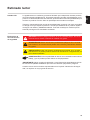
Explanation of
Safety Instruc-
tions
If you see any of the symbols depicted in the "Safety Rules," special care is required.
DANGER! Indicates an immediate danger. Death or serious injury may result if
appropriate precautions are not taken.
WARNING! Indicates a possibly dangerous situation. Death or serious injury may
result if appropriate precautions are not taken.
CAUTION! Indicates a situation where damage or injury could occur. Minor injury
or damage to property may result if appropriate precautions are not taken.
NOTE! Indicates the possibility of flawed results and damage to the equipment.
IMPORTANT! Indicates tips for correct operation and other particularly useful information.
It does not indicate a potentially damaging or dangerous situation.

4

5
EN-US
Contents
Safety rules ................................................................................................................................................ 7
General ................................................................................................................................................. 7
Environmental Conditions..................................................................................................................... 7
Qualified Service Engineers.................................................................................................................. 8
Copyright............................................................................................................................................... 8
Backup.................................................................................................................................................. 8
FCC / RSS Compliance ........................................................................................................................ 9
Warning notices on the device.............................................................................................................. 9
Installation.................................................................................................................................................. 10
Installation Checklist ............................................................................................................................. 10
Mounting ............................................................................................................................................... 10
Circuit Protection................................................................................................................................... 11
Line Wiring............................................................................................................................................ 11
Connect Current Transformers ............................................................................................................. 14
CT Wiring.............................................................................................................................................. 14
Connecting the Data Communication Signals ......................................................................................15
Terminating Resistors........................................................................................................................... 15
Modbus RTU......................................................................................................................................... 16
Set Terminating Resistor ...................................................................................................................... 16
Set Baud Rate....................................................................................................................................... 17
Configuration Web Interface ................................................................................................................. 17
Operation ................................................................................................................................................... 18
Power Status LEDs............................................................................................................................... 18
Modbus Communication LEDs ............................................................................................................. 19
Technical Data ........................................................................................................................................... 20
Accuracy ............................................................................................................................................... 20
Measurement........................................................................................................................................ 20
Models and Electrical............................................................................................................................ 20
Certifications ......................................................................................................................................... 21
Environmental....................................................................................................................................... 21
Mechanical............................................................................................................................................ 21
Fronius Manufacturer's Warranty.......................................................................................................... 21

6

7
EN-US
Safety rules
General
Environmental
Conditions
The device has been manufactured using state-of-the-art technology and ac-
cording to recognized safety standards. If used incorrectly or misused, howev-
er, it can cause
- injury or death to the operator or a third party
- damage to the device and other material assets belonging to the operat-
ing company
- inefficient operation of the equipment
All persons involved in start-up operation, maintenance and servicing for the
device must
- be suitably qualified
- have knowledge of and experience in dealing with electrical installations
and
- have completely read and followed these operating instructions
The operating instructions must always be at hand wherever the device is be-
ing used. In addition to the operating instructions, all applicable local rules and
regulations regarding accident prevention and environmental protection must
also be followed.
All safety and danger notices on the device
- must be kept in a legible state
- must not be damaged/marked
- must not be removed
- must not be covered, pasted or painted over
The terminals can reach high temperatures.
Only operate the device when all protection devices are fully functional. If the
protection devices are not fully functional, there is a risk of
- injury or death to the operator or a third party
- damage to the device and other material assets belonging to the operat-
ing company
- inefficient operation of the device
Safety devices that are not fully functional must be repaired by an authorized
specialist before the device is turned on.
Never bypass or disable protection devices.
For the location of the safety and danger notices on the device, refer to the
section headed "General" in the operating instructions for the device.
Any equipment malfunctions which might impair safety must be remedied im-
mediately before the device is turned on.
Your personal safety is at stake!
Operation or storage of the device outside the stipulated area will be deemed
as "not in accordance with the intended purpose." The manufacturer is not re-
sponsible for any damages resulting from unintended use.
For exact information on permitted environmental conditions, please refer to
the "Technical data" in the operating instructions.

8
Qualified Service
Engineers
Copyright
Backup
The servicing information contained in these operating instructions is intended
only for the use of qualified service engineers. An electric shock can be fatal.
Do not carry out any actions other than those described in the documentation.
This also applies to qualified personnel.
All cables and leads must be secured, undamaged, insulated, and adequately
dimensioned. Loose connections, scorched, damaged, or under-dimensioned
cables and leads must be repaired immediately by an authorized specialist.
Maintenance and repair work must only be carried out by authorized person-
nel.
It is impossible to guarantee that externally procured parts are designed and
manufactured to meet the demands made on them, or that they satisfy safety
requirements. Use only original spare parts (also applies to standard parts).
Do not carry out any alterations, installations, or modifications to the device
without first obtaining the manufacturer’s permission.
Components that are not in perfect condition must be changed immediately.
Copyright of these operating instructions remains with the manufacturer.
Text and illustrations are technically correct at the time of going to print. The
right to make modifications is reserved. The contents of the operating instruc-
tions shall not provide the basis for any claims whatsoever on the part of the
purchaser. If you have any suggestions for improvement, or can point out any
mistakes that you have found in the operating instructions, we will be most
grateful for your comments.
The user is responsible for backing up any changes made to the factory set-
tings. The manufacturer accepts no liability for any deleted personal settings.

9
EN-US
FCC / RSS Com-
pliance
Warning notices
on the device
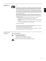
FCC
This device corresponds to the limit values for a digital device of class B in
accordance with Part 15 of the FCC regulations. The limit values should pro-
vide adequate protection against harmful interference in homes. This device
creates and uses high frequency energy and can interfere with radio com-
munications when not used in accordance with the instructions. However,
there is no guarantee against interference occurring in a particular installa-
tion.
If this device interferes with radio or television reception when turning the de-
vice on and off, it is recommended that the user solve this with one or more
of the following measures:
- adjust or reposition the receiving antenna
- increase the distance between the device and the receiver
- connect the device to another circuit, which does not include the receiv-
er
- for further support, please contact the retailer or an experienced radio/
TV technician.
Industry Canada RSS
The device corresponds to the license-free Industry Canada RSS stan-
dards. Operation is subject to the following conditions:
(1) The device may not cause harmful interference
(2) The device must accept any interference received, including interfer-
ence that may cause undesired operation.
Safety symbols:
To avoid electric shocks:
- Do not dismantle or modify the device
- Do not allow any water to enter the device
- Do not allow any foreign substances or material to enter the device
- Do not touch any connections directly
RCM Symbol - The product complies with the Australian laws.

10
Installation
Installation
Checklist
See the sections referenced below for installation details
Turn off power before making line voltage connections
Mount the Fronius Smart Meter (see “Mounting“)
Connect circuit breakers or fuses and disconnects (see “Circuit Protection“)
Connect the line voltage wires to the meter‘s terminal block (see “Line Wiring“)
Mount the Current Transformers (CTs) around the line conductors. Make sure the CTs
face the correct direction. An arrow might indicate either the load or the source (public
grid) (see “Connect Current Transformers“)
Connect the twisted white and black wires form the CTs to the terminal block on the
meter, matching the wire colors to the white and black dots on the meter label (see
“CT Wiring“)
Check that the CT phases match the line voltage phases (see “Connect Current
Transformers“)
Record the CT rated current for each meter, because it will be required during setup
Connect the output terminals of the Fronius Smart Meter to the monitoring equipment
(see “Connecting the Data Communication Signals“)
If necessary set terminating resistors (see “Terminating Resistors“)
Check that all the wires and plugs are securely installed in the terminal blocks by tug-
ging on each wire
Turn on the power to the Smart Meter
Verify that the LEDs indicate correct operation. If there is a consumption of power and
all generated power sources are turned off, then the LEDs from the used phases
should flash green (see “Operation“).
Check your Fronius System monitoring software. In order to ensure compatibility be-
tween the inverter and the Smart Meter, software must always be kept up-to-date. The
update can be started via the inverter website.
Set CT-Ratio and Grid Type on the web interface of the Fronius Datamanager in Set-
tings - Meter - Settings (see “Configuration web interface“)
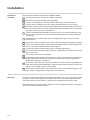
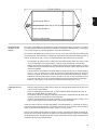
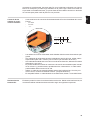
Mounting The Fronius Smart meter has two mounting holes spaced 5.375 in. (137 mm) apart (center-
to-center). These mounting holes are normally obscured by the detachable screw termi-
nals. Remove the screw terminals to mark the hole positions and mount the meter.
Self-tapping sheet metal screws are included. Do not over-tighten the screws, as long-term
stress on the case can cause cracking.
1
2
3
4
5
6
7
8
9
10
11
12
13
14
15

11
EN-US
Circuit Protection The Fronius Smart Meter is considered “permanently connected equipment“ and requires
a disconnect means (circuit breaker, switch or disconnect) and overcurrent protection (fuse
or circuit breaker).
The Fronius Smart Meter only draws 10-30 mA, so the rating of any switches, disconnects,
fuses and / or circuit breakers is determined by the wire gauge, the mains voltage and the
current interrupting rating required.
- The switch, disconnect or circuit breaker must be within sight and as close as practi-
cable to the Fronius Smart Meter and must be easy to operate.
- Use circuit breakers or fuses rated for 20 amps or less.
- Use ganged circuit breakers when monitoring more than one line voltage.
- The circuit breakers or fuses must protect the mains terminals labeled L1, L2 and L3.
In the rare cases where neutral has overcurrent protection, the overcurrent protection
device must interrupt both neutral and ungrounded conductors simultaneously.
- The circuit protection / disconnect system must meet IEC 60947-1 and IEC 60947-3,
as well as all national and local electrical codes.
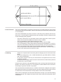
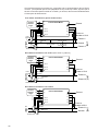
Line Wiring - Always turn off power before connecting the line voltage inputs to the Fronius Smart
Meter.
- For the line voltage wires, 16 to 12 AWG stranded wire, type THHN, MTW or THWN,
600 V are recommended.
- Do not place more than one wire per screw terminal; use separate wire nuts or termi-
nal blocks if needed.
- Verify that the line voltages match the line-to-line and line-to-neutral values printed in
the white box on the front label.
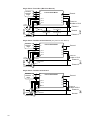
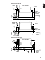
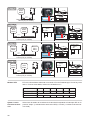
Connect each conductor to the appropriate phase; also connect ground and neutral (if ap-
plicable). The neutral connection “N“ is not required on delta models but we recommend
connecting it to ground if neutral is not present.
The screw terminal can handle wire up to 12 AWG. Connect each voltage line to the green
terminal block as shown in the following figures. After the voltage lines have been connect-
ed, make sure both terminal blocks are fully seated in the Fronius Smart Meter.
When power is first applied, check that the LEDs behave normally. If you see LEDs flashing
red-green-red-green, the voltage is too high for this model, so disconnect the power switch
immediately!
153 mm (6.02 in)
38 mm (1.50 in) High
Ø
9.8 mm (0.386 in)
Ø
5.1 mm (0.200 in)
85.1 mm (3.35 in)
136.6 mm (5.375 in)

12
Single-Phase Three-Wire (Mid-Point Neutral)
Single-Phase Two-Wire without Neutral (only 240V-3 and 480V-3)
Single-Phase Two-Wire with Neutral
Ground
WHITE
BLACK
CT L2
CT L3
CT L1
L2
L3
N
L1
Fronius Smart Meter
Fronius
Datama-
nager
D+
D-
-
D+
D-
-
Shorting
Jumper
e.g. 120 Vac (US),
240 Vac (AUS)
e.g. 120 Vac (US),
240 Vac (AUS)
e.g. 120 Vac (US),
240 Vac (AUS)
Neutral
Phase L1
Phase L2
LOAD
WHITE
BLACK
LINE
Source
Faces
Current
Transformers
Load
Faces
Fuses or
Breaker ≤ 20 A
Ground
WHITE
BLACK
CT L2
CT L3
CT L1
L2
L3
N
L1
Fronius Smart Meter
Shorting
Jumper
Fronius
Datama-
nager
D+
D-
-
D+
D-
-
Phase L1
Phase L2
LOAD
WHITE
BLACK
LINE
Source
Faces
Current
Transformers
Load
Faces
Fuses or
Breaker ≤ 20 A
Ground
WHITE
BLACK
CT L2
CT L3
CT L1
L2
L3
N
L1
Fronius Smart Meter
Fronius
Datama-
nager
D+
D-
-
D+
D-
-
Phase L1
Neutral
LOAD
WHITE
BLACK
LINE
Source
Faces
Current
Transformers
Load
Faces
Fuses or
Breaker ≤ 20 A
Shorting
Jumper

13
EN-US
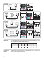
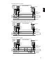
Three-Phase Four-Wire Wye
Three-Phase Three-Wire Delta without Neutral (only 240V-3 and 480V-3)
Three-Phase Four-Wire Stinger
Ground
WHITE
BLACK
CT L2
CT L3
CT L1
L2
L3
N
L1
Fronius Smart Meter
Fronius
Datama-
nager
D+
D-
-
D+
D-
-
Neutral
Phase L1
Phase L2
Phase L3
LOAD
WHITE
BLACK
WHITE
BLACK
LINE
Source
Faces
Current
Transformers
Load
Faces
Fuses or
Breaker ≤ 20 A
Ground
WHITE
BLACK
CT L2
CT L3
CT L1
L2
L3
N
L1
Fronius Smart Meter
Fronius
Datama-
nager
D+
D-
-
D+
D-
-
Load
Faces
Fuses or
Breaker ≤ 20 A
Phase L1
Phase L2
Phase L3
LOAD
WHITE
BLACK
WHITE
BLACK
LINE
Source
Faces
Current
Transformers
Ground
WHITE
BLACK
CT L2
CT L3
CT L1
L2
L3
N
L1
Fronius Smart Meter
Fronius
Datama-
nager
D+
D-
-
D+
D-
-
Neutral
Phase L1
Phase L2
Phase L3
(Wild Leg)
LOAD
WHITE
BLACK
WHITE
BLACK
LINE
Source
Faces
Current
Transformers
240 Vac
240 Vac
240 Vac 120 Vac
208 Vac
120 Vac
Load
Faces
Fuses or
Breaker ≤ 20 A

14
Connect Current
Transformers
The current transformer must generate 333.33 millivolts AC at rated current. See the cur-
rent transformer data sheets for CT ratings.
- Do not use ratio or current output such as 1 amp or 5 amp output models!
- See the CT data sheets for the maximum input current ratings.
- Be careful to match the CTs with the voltage phases. Make sure the CT L1 is measur-
ing the current on the same phase being monitored by the L1 voltage input and the
same for phases L2 and L3. Use the supplied colored labels or colored tape to identify
the CT leads.
- To minimize current measurement noise, avoid extending the CT wires, especially in
noisy environments. If it is necessary to extend the wires, use twisted pair cable 22 to
14 AWG, rated for 300 V or 600 V (not less than the service voltage) and shielded if
possible
- Make sure the CTs face the correct direction. An arrow might indicate either the load
or the source (public grid)
- If you see strange readings on unused phases, jumper the unused CT inputs: for each
unused CT, connect a short cable from the terminal marked with a white dot to the ter-
minal marked with a black dot.
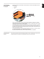
Install the CTs around the conductor to be measured and connect the CT leads to the Fro-
nius Smart Meter. Always turn off power before disconnecting any live conductors. Put the
line conductors through the CTs as shown in the previous section.
CTs are directional. If they are mounted backwards or with their white and black wires
swapped the measured power will be negative. The status LEDs indicate negative mea-
sured power by flashing red.
Split-core CTs can be opened for installation around the conductor. A nylon cable tie may
be secured around the CT to prevent inadvertent opening.
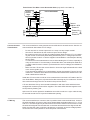
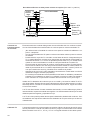
CT Wiring The current transformers connect to the six position black screw terminal block. Connect
the white and black CT wires to the Fronius Smart Meter terminals marked CT L1, CT L2
and CT L3. Excess length may be trimmed from the wires if desired. Connect each CT with
the white wire aligned with the white dot on the label and the black wire aligned with the
black dot. Note the order in which the phases are connected, as the line voltage phases
must match the current phases for accurate power measurement.
Three-Phase Two-Wire Corner Grounded Delta (only 240V-3 and 480V-3)
WHITE
BLACK
CT L2
CT L3
CT L1
L2
L3
N
L1
Fronius Smart Meter
Fronius
Datama-
nager
D+
D-
-
D+
D-
-
Phase L1
Phase L2
(Ground)
Phase L3
LOAD
WHITE
BLACK
LINE
Source
Faces
Current
Transformers
Shorting
Jumper
Load
Faces
Fuses or
Breaker ≤ 20 A

15
EN-US
Connecting the
Data Communica-
tion Signals
- Connect the Data Communication Terminal from the Fronius Smart Meter to the Fro-
nius Inverter
- D+ to D+
- D- to D-
- - to -
- The Fronius Solar Meter outputs are electrically isolated from dangerous voltages.
- If the output wiring is near line voltage wiring, use wires or cables with a 300 V or 600
V rating (never less than the service voltage).
- If the output wiring is near bare conductors, it should be double insulated or jacketed.
- You may install two wires into each screw terminal by twisting the wires together, in-
serting them into the terminal and tightening them securely. Note: a loose wire can dis-
able an entire network section.
- Use shielded twisted-pair cable to prevent interference. If there is no common conduc-
tor, connect the shield to the - (respectively C) terminal.
- Shielded 24 AWG Cat5, Cat5e or 23-24 AWG Cat6 cable is acceptable.
Terminating Re-
sistors
The system might work without terminating resistors. Due to interferences, the use of ter-
minating resistors according to the following schemes are recommended.
D-
-
-
1
3
5
7
9
D+
+
+
0
2
4
6
8
I IO RS485

16
Modbus RTU The Fronius Smart Meter must be connected to the Fronius Datamanager. If only one Fro-
nius Smart Meter is installed, the Modbus Address is 1.
Set Terminating
Resistor
Select the state of the terminating resistor by setting DIP switch Down (= terminating resis-
tor OFF) or Up (= terminating resistor ON).
D- / D+ -
120 Ω
*)
Modbus RTU
Slave
D- / D+ -
D- / D+ -
120 Ω
*)
Data (Recommended cable:
Li2YCY(TP) or CAT6a)
Data (Recommended cable:
Li2YCY(TP) or CAT6a)
Data (Recommended cable:
Li2YCY(TP) or CAT6a)
max.
300 m
max.
300 m
max.
300 m
OPTION 1
OPTION 1
OPTION 3
OPTION 3
OPTION 4
OPTION 4
OPTION 2
OPTION 2
Fronius
Smart
Meter
Fronius
Smart
Meter
Modbus
RTU
Slave
Data (Recommended cable:
Li2YCY(TP) or CAT6a)
max.
300 m
Fronius
Smart
Meter
Modbus
RTU
Slave
Fronius
Smart
Meter
Modbus
RTU
Slave
1 2 3 4 5 6 7 8
CTS 206-8 T517
OFF
1 2 3 4 5 6 7 8
CTS 206-8 T517
ON
1 2 3 4 5 6 7 8
CTS 206-8 T517
ON
1 2 3 4 5 6 7 8
CTS 206-8 T517
ON
PIN7
PIN7
PIN7
PIN7
Modbus RTU
Slave
Modbus RTU
Slave
DIP Switch 1 2 3 4 5 6
Up (1) value 1 2 4 8 16 32
Address Modbus Address 1
Position 1, Up 0, Down 0, Down 0, Down 0, Down 0, Down

17
EN-US
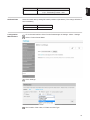
Set Baud Rate Select the baud rate by setting DIP switch position 8 (see below). The change will take ef-
fect immediately.
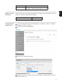
Configuration
Web Interface
Go to the web interface of the Fronius Datamanager in Settings - Meter - Settings
Select “Fronius Smart Meter“
Click “Settings“
Set Location of the meter, CT-Ratio and Grid Type
DIP Switch 7
Position 0, Down - Terminating resistor = OFF
1, Up - Terminating resistor = ON
Baud Rate DIP Switch 8
9600 (default) 0, Down
1
2
3
4

18
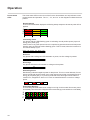
Operation
Power Status
LEDs
The three status LEDs on the front of the Fronius Smart Meter can help indicate correct
measurements and operation. The “L1”, “L2”, and “L3” on the diagrams indicate the three
phases:
Normal Startup
The Fronius Smart Meter displays the following startup sequence whenever power is first
applied.
Consuming Power
Any phase with the LEDs flashing green is indicating normal positive power (Import of
energy from public grid).
If the inverter or any other power source is not producing power and some minimal power
is being used, the LEDs should be flashing green. This is normal, when the inverter is in
its 5 minute startup cycle.
No Power
Any phase with a solid green LED indicates no power, but line voltage is present.
No Voltage
Any phase LED that is off indicates no voltage on that phase.
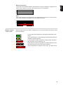
Generating Power
Red flashing indicates negative power for that phase. This is a normal behavior if more
power is produced (by the inverter or any other power source) than consumed (Export of
energy to the public grid). If no power is produced at all, this might indicate either re-
versed CT's, swapped CT wires or CT's are not matched with the correct line voltage
phase.
Overvoltage Warning
The following indicates that the line voltage is too high for this model. Disconnect power
immediately! Check the line voltages and the meter ratings (in the white box on the label).
1.0sec
1.0sec1.0sec
GreenYellowRed
GreenYellowRed
GreenYellowRed
C
B
A
Green
Off
Green
Off
Green
Off
Green
Off
Red
Off
Red
Off
Red
Off
C
1.0sec
GR GR GR GR GR GR
GR GR GR GR
GR GR
GR GR GR GR
GR GR
C
B
A

19
EN-US
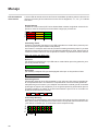
Modbus Commu-
nication LEDs
Near the upper left corner, there is a diagnostic Com (communication) LED that can indi-
cate the following:
Meter Not Operating
If none of the LEDs are illuminated, check that the correct line voltages are applied to the
meter. If the voltages are correct, call customer service for assistance.
Error
If the meter experiences an internal error, all LEDs will light up red for 3 or more seconds.
If you see this happen repeatedly, return the meter for service.
Off
Off
Off
C
B
A
3.0sec
Red
Red
Red
C
B
A
A short green flash indicates a valid packet addressed to this
device.
Short yellow flashes or rapid flashing indicate valid packets ad-
dressed to different devices.
A one-second red flash indicates an invalid packet: bad baud
rate, bad CRC, noise, bad parity, etc.
Rapid red/yellow flashing indicates a possible address conflict
(two devices with the same DIP switch address).
Solid red indicates the address is set to zero: an invalid choice.
Green Off
Yellow Off
Red
YR YR YR
Red

20
Technical Data
Accuracy Normal Operation
Line voltage: -20% to +15% of nominal
Power factor: 1.0
Frequency: 48 - 62 Hz
Ambient Temperature: 23° C ± 5° C
CT Current: 5% - 100% of rated current
Accuracy: ± 0.5% of reading
Measurement Update Rate: 0.1 second. Internally, all measurements are performed at this rate.
Startup Time: ~1.0 second. The Fronius Smart Meter starts communicating this long after
AC voltage is applied. Energy measurement starts 50-100 milliseconds after AC is applied.
Default CT Phase Angle Correction: 0.0 degrees.
Models and Elec-
trical
The Fronius Smart Meter has an optional neutral connection that may be used for measur-
ing wye circuits. In the absence of neutral, voltages are measured with respect to ground.
The Fronius Smart Meter uses the phase L1 (øA) and phase L2 (øB) connections for pow-
er.
Over-Voltage Limit: 125% of nominal Vac. Extended over-voltage operation can damage
the Fronius Smart Meter and void the warranty.
Over-Current Limit: 120% of rated current. Exceeding 120% of rated current will not harm
the Fronius Smart Meter but the current and power will not be measured accurately.
Maximum Surge: 4 kV according to EN 61000-4-5
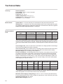
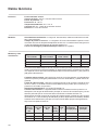
Power Consumption: The following table shows maximum volt-amperes, the power sup-
ply ranges, typical power consumption, and typical power factors with all three phases
powered at nominal line voltages. The power supply consumes most of the total power,
while the measurement circuitry draws 1-10% of the total (6-96 milliwatts per phase, de-
pending on the model). Due to the design of the power supply, the Fronius Smart Meter
draws slightly more power at 50 Hz.
*) The Rated VA is the maximum at 115% of nominal Vac at 50 Hz. This is the same as the
value that appears on the front label of the Fronius Smart Meter.
Maximum Power Supply Voltage Range: -20% to +15% of nominal (see table above).
For the 3D-240 service, this is -20% of 208 Vac (166 Vac) to +15% of 240 Vac (276 Vac).
Operating Frequencies: 50 / 60 Hz
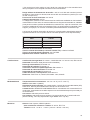
Measurement Category: CAT III
Meter Service
Type
Nominal Vac
Line-to-Neutral
Nominal Vac
Line-to-Line
Phases Wires
240V-3 UL 120 208-240 1 - 3 2 - 4
480V-3 UL 277 480 1 - 3 2 - 4
600V-3 UL 347 600 1 - 3 2 - 4
Meter Ser-
vice Type
Real Pow-
er (60 Hz)
Real Pow-
er (50 Hz)
Power
Factor
(50 Hz)
Rated
VA *)
Power Supply
Range (Vac)
Power Sup-
ply Terminals
240V-3 UL 1.2 W 1.5 W 0.70 4 VA 166 - 276 L1 and L2
480V-3 UL 1.2 W 1.6 W 0.70 3 VA 384 - 552 L1 and L2
600V-3 UL 1.0 W 1.3 W 0.76 3 VA 278 - 399 N and L1
Page is loading ...
Page is loading ...
Page is loading ...
Page is loading ...
Page is loading ...
Page is loading ...
Page is loading ...
Page is loading ...
Page is loading ...
Page is loading ...
Page is loading ...
Page is loading ...
Page is loading ...
Page is loading ...
Page is loading ...
Page is loading ...
Page is loading ...
Page is loading ...
Page is loading ...
Page is loading ...
Page is loading ...
Page is loading ...
Page is loading ...
Page is loading ...
-
 1
1
-
 2
2
-
 3
3
-
 4
4
-
 5
5
-
 6
6
-
 7
7
-
 8
8
-
 9
9
-
 10
10
-
 11
11
-
 12
12
-
 13
13
-
 14
14
-
 15
15
-
 16
16
-
 17
17
-
 18
18
-
 19
19
-
 20
20
-
 21
21
-
 22
22
-
 23
23
-
 24
24
-
 25
25
-
 26
26
-
 27
27
-
 28
28
-
 29
29
-
 30
30
-
 31
31
-
 32
32
-
 33
33
-
 34
34
-
 35
35
-
 36
36
-
 37
37
-
 38
38
-
 39
39
-
 40
40
-
 41
41
-
 42
42
-
 43
43
-
 44
44


Fronius Smart Meter 240V-3 UL Operating Instructions Manual
- Type
- Operating Instructions Manual
- This manual is also suitable for
Ask a question and I''ll find the answer in the document
Finding information in a document is now easier with AI
in other languages
- español: Fronius Smart Meter 240V-3 UL
Related papers
-
 Fronius IG Plus A 3.8-1 UNI Operating Instructions Manual
-
Fronius 42 User manual
-
Fronius TS 65A-3 User guide
-
 Fronius 24.0-3 480 Symo Advanced Owner's manual
-
Fronius Energy Package User manual
-
 Fronius Ohmpilot Operating
-
Fronius Symo Advanced 20.0-3 480 User manual
-
-
 Fronius Primo GEN24 Single Phase Hybrid User manual
-
 Fronius Symo Hybrid Installation Instructions Manual


Other documents
-
Victron energy Energy Storage System Owner's manual
-
-
 Solar-Log 300 User manual
-
Freedom Lite Home 10/8 Installation guide
-
Rauch Datamanager Operating instructions
-
 Smappee Energy monitor Installation guide
-
ABB SmarTac Applications Manual
-
MYPV AC-THOR Operating instructions
-
 Verdigris EV2 Energy Data Gateway User manual
-
Victron energy Venus GX Owner's manual


