Page is loading ...

DA103
DA103DA103
DA103-
--
-217 VGA Line Receiver
217 VGA Line Receiver217 VGA Line Receiver
217 VGA Line Receiver
User’s Guide
400-0522-004
1
Welcome!
We greatly appreciate your purchase of the DA103-217 VGA Line Receiver.
We are sure you will find it reliable and simple to use. Superior performance
for the right price, backed by solid technical and customer support is what
ALTINEX has to offer.
We are committed to providing our customers with
Signal Management Solutions
®
to the most demanding audiovisual
installations at competitive pricing and we welcome you to join the ranks of
our many satisfied customers throughout the world.
1. Precautions and Safety Warnings
Please read this manual carefully before using your DA103-217 and keep it
handy for future reference. These safety instructions are to ensure the long
life of your DA103-217 and to prevent fire and shock hazards. Please read
them carefully and heed all warnings.
1.1 General
• Do not open the unit or power supply, there are high-voltage
components inside.
• There are no user serviceable parts inside. Qualified ALTINEX service
personnel must perform all service on the DA103-217.
1.2 Handling
• Place the DA103-217 in a dry area away from dust and moisture.
• To prevent fire or shock, do not expose this unit to water or moisture.
Do not place the DA103-217 in direct sunlight, near heaters, or
heat-radiating appliances, or near any liquid. Exposure to direct
sunlight, smoke, or steam can harm internal components.
• Handle the unit carefully. Dropping or jarring can cause damage.
• Do not pull any cables that are attached to the DA103-217.
• Do not place heavy objects on top of the DA103-217.
• If the DA103-217 is not used for an extended period, disconnect the
adapter from the wall to avoid fire, shock, and power loss.
1.3 Cleaning
• Unplug the DA103-217 adapter before cleaning.
• Clean only with a dry cloth. Never use strong detergents or solvents
such as alcohol or thinner. Do not use a wet cloth or water to clean the
unit. Do not open the unit to clean.
1.4 FCC Notice
• This device complies with Part 15 of the FCC Rules. Operation is
subject to the following two conditions: (1) This device may not cause
harmful interference, and (2) this device must accept any interference
received, including interference that may cause undesired operation.
• This equipment has been tested and found to comply with the limits for
a Class A digital device, pursuant to Part 15 of the FCC Rules. These
limits are designed to provide reasonable protection against harmful
interference when the equipment is operated in a commercial
environment. This equipment generates, uses, and can radiate radio
frequency energy and if not installed and used in accordance with
instructions found herein, may cause harmful interference to radio
communications. Operation of this equipment in a residential area is
likely to cause harmful interference in which case the user will be
required to correct the interference at his own expense.
• Any changes or modifications to the unit not expressly approved by
ALTINEX, Inc. could void the user’s authority to operate the
equipment.
2. Installation Procedures
Step 1. Determine if the computer needs to receive available video resolutions from the display device or from the internal memory of the DA103-217. Set the
EDID switch to INT for using the DA103-217 internal memory or EXT to use the display resolutions. The switch is located on the side of the unit and
is accessible through a rectangular opening.
Step 2. Use the video cable provided and connect one end to the display and the other end to the output of the DA103-217.
Step 3. Connect the long cable from the source to the DA103-217 video input.
Step 4. Apply power to the DA103-217 using the adapter provided. The Power/Signal Present LED is RED if there is power
and GREEN if a signal is present.
Step 5. Set the adjustment potentiometers as follows:
EQ= Minimum (full CCW) GAIN = Minimum (full CCW) SYNC ADJ = Midway (50%)
Step 6. If the image is visible, start by adjusting the EQ until the image is clear. A 250 ft (76 m) cable requires near maximum equalization. If there is no
image, start by slowly increasing the SYNC ADJ. Stop adjusting when the image is visible.
Step 7. While viewing the image on the display, fine-tune the image using the EQ and GAIN adjustments.
Step 8. Next, fine-tune the SYNC ADJ for the best image/screen position.
Step 9. The DA103-217 is now operational.
3. Limited Warranty/Return Policies
Please see the ALTINEX website at www.altinex.com for details on warranty and return policies.

DA103
DA103DA103
DA103-
--
-217 VGA Line Receiver
217 VGA Line Receiver217 VGA Line Receiver
217 VGA Line Receiver
User’s Guide
400-0522-004
2
4. Technical Specifications
Specifications are subject to change. See www.altinex.com for up-to-date information.
Features/Description DA103-217
Inputs
VGA 15-pin HD F (1)
Output
Video 15-pin HD F (1)
Power
DC Power (adapter) DC power jack (1)
Compatibility
Signal Types
RGB, RGsB, RGBS,
RGBHV, YPbPr
Video Signal
Resolutions
VGA through UXGA
480p through 1080i
EDID Memory
Selectable for
internal or external
Accessories Included
Video Cable VGA to Display, 18 in
Power Adapter +9VDC, 1.1 A
Optional Accessories
Ultra-Thin VGA
Video Cable
CB3000PV Series
Table 1. DA103-217 General
Mechanical DA103-217
Material 0.091 in Al
Color Black
Height 0.8 in (20 mm)
Width 3.9 in (99 mm)
Depth 1.6 in (41 mm)
Weight 0.2 lb (0.1 kg)
Shipping Weight (approx.) 1.0 lb (0.5 kg)
T° Operating 10°C-35°C
T° Maximum 0°C-50°C
Humidity
90% non-condensing
MTBF (calculations) 40,000 hrs (min.)
Table 2. DA103-217 Mechanical
Electrical DA103-217
Video Adjustments
Gain 0 to 3 dB
Sync Threshold 0.5 to 4.5 V
Equalization Up to 250 ft (76 m)
Input
Video Signal 1.4 Vp-p max
Video Impedance 75 ohms
Sync Signal TTL (+/-)
Sync Impedance 10 kohms
Sync Threshold 4.5 V nominal
Output
Video Gain 0 dB +/- 0.5 dB nominal
Video Impedance 75 ohms
Sync Signal TTL (+/-)
Sync Impedance 22 ohms
Sync Polarity
Plus or Minus
(follows input)
Power Consumption
+9V 250 mA
Total Power 2.25 W max
Table 3. DA103-217 Electrical

DA103
DA103DA103
DA103-
--
-217 VGA Line Receiver
217 VGA Line Receiver217 VGA Line Receiver
217 VGA Line Receiver
User’s Guide
400-0522-004
3
5. About Your DA103-217
• Recover signal after 250 ft (76 m) of ultra-thin VGA cable
• Equalization/gain adjust for image optimization
• Compact and sturdy
• AGC control for sync restoration
• Internal or external EDID selection
The DA103-217 is a VGA line receiver for long cable runs using RGBHV or VGA type cables. It connects to the display end and allows adjustment of video
equalization, gain, and sync threshold to recover degraded analog signals and improve video quality. The DA103-217 can compensate for up to 250 ft (76 m) of
ultra thin VGA cable.
Cable runs over 75 ft (23 m) probably need and should have this line receiver. In applications without the DA103-217, customers may complain about image
smearing, blurriness, and other distortions. The DA103-217 eliminates smearing and other distortions while making letters and graphics sharp and legible.
It is recommended to install the DA103-217 at the display end for best results. Its small size allows easy installation behind a display or in a ceiling space while
the metal enclosure provides strength and protection for long life and reliability.
Other features include a signal present indicator that shows when a signal is present, AGC control for sync recovery, and internal or external EDID selection for
proper computer settings to match display resolution.
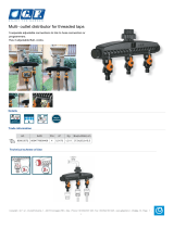
POWER/SIGNAL PRESENT
INPUT
VIDEO
INPUT
VIDEO
GREEN = SIGNAL PRESENT
RED = POWER
EDID SWITCH
INTERNAL/EXTERNAL
POWER 9V, 0.25A

DA103
DA103DA103
DA103-
--
-217 VGA Line Receiver
217 VGA Line Receiver217 VGA Line Receiver
217 VGA Line Receiver
User’s Guide
400-0522-004
4
6. Application Diagrams
Diagram 1: Typical Setup

DA103
DA103DA103
DA103-
--
-217 VGA Line Receiver
217 VGA Line Receiver217 VGA Line Receiver
217 VGA Line Receiver
User’s Guide
400-0522-004
5
Diagram 2: Internal View

DA103
DA103DA103
DA103-
--
-217 VGA Line Receiver
217 VGA Line Receiver217 VGA Line Receiver
217 VGA Line Receiver
User’s Guide
400-0522-004
6
7. Operation
The DA103-217 will operate successfully as long as cables are attached
properly and other technical specifications are followed.
The adjustments on the DA103-217 Line Receiver are available to
fine-tune the output image and to compensate for errors induced by cable
quality, cable length, and variations in equipment.
7.1 Adjustments
7.1.1 Eq
Video equalization is provided to fine-tune the displayed image on the
remote display. Typically, for short cable runs the equalization will be
set to near minimum. Cable lengths up to 250 ft (76 m) will require
near maximum equalization.
7.1.2 Gain
Video gain is provided to restore signal level and brightness to the
remote display. Typically, this adjustment is made after the
equalization has been set.
7.1.3 Sync Adj
The sync threshold adjustment allows changes to be made in the sync
processing circuitry and to help recover and compensate for degraded
signals. Always start this adjustment with the potentiometer set to the
50% position and make adjustment in small increments.
8. Troubleshooting Guide
We have carefully tested and found no problems in the supplied
DA103-217; however, we would like to offer suggestions for the following:
8.1 LED is Not Red
The LED should be ON and RED when power is applied and there is no
video signal present. If the LED is ON and GREEN, the unit is receiving
power and a SYNC signal.
Cause 1: No AC power.
Solution:
Verify the adapter is plugged into a working AC outlet and
that the outlet has power.
Cause 2: Adapter is not plugged into DA103-217.
Solution:
Verify the DC power plug coming from the AC adapter is
plugged all the way into the DA103-217.
Cause 3: The DA103-217 has a problem.
Solution:
If there is AC power to the adapter and the LED still does not
turn on, call ALTINEX at (714) 990-2300.
8.2 LED is Not Green
Cause 1: There is no power.
Solution:
Disconnect the video input from the DA103-217 and verify the
LED is ON and RED indicating power is present. Reconnect
the computer's video output. If the LED is still not GREEN see
Cause 2.
Cause 2: There is no sync signal.
Solution:
Verify the computer output is operating correctly by
connecting it directly to the local monitor. If the display is
good, call ALTINEX at (714) 990-2300.
8.3 No Remote Image
Cause 1: The source has a problem.
Solution:
Check the image on the local monitor and verify the quality is
good. If the local image is good, see Cause 2.
Cause 2: Cable connections are incorrect.
Solution:
Make sure that cables are connected properly. Also, make sure
that the continuity and wiring are good. If there is still no
image present, see Cause 3.
Cause 3: Video equalization required.
Solution:
Adjust the EQ potentiometer on the DA103-217.
In general, cable runs less then 50 ft (15 m) require little or no
video equalization and should be set to minimum to start.
Cable runs up to 250 ft (76 m) will require maximum
equalization.
8.4 Remote Image Quality is Poor
Cause 1: The source has a problem.
Solution:
Check the image on the local monitor and verify the quality is
good. If the local image is good, see Cause 2.
Cause 2 Poor signal transmission.
Solution:
Check the cables for continuity and make sure that
connections are wired properly to verify that there is good
signal transmission. If the image is still not correct, call
ALTINEX at (714) 990-2300.
Cause 3: Video equalization required.
Solution:
Slowly adjust the EQ, GAIN, and SYNC ADJ potentiometers
on the DA103-217 while viewing the display. If the image still
cannot be set correctly, call ALTINEX at (714) 990-2300.
/