Page is loading ...

Installation MIPP
Release
06
04/2019
Technical support
https://hirschmann-support.belden.com
User Manual
Installation
Modular Industrial Patch Panel
MIPP
040156002060419000

2019-04-29
Installation MIPP
Release
06
04/2019
The naming of copyrighted trademarks in this manual, even when not specially indicated, should
not be taken to mean that these names may be considered as free in the sense of the trademark
and tradename protection law and hence that they may be freely used by anyone.
© 2019 Hirschmann Automation and Control GmbH
Manuals and software are protected by copyright. All rights reserved. The copying, reproduction,
translation, conversion into any electronic medium or machine scannable form is not permitted,
either in whole or in part. An exception is the preparation of a backup copy of the software for
your own use.
The performance features described here are binding only if they have been expressly agreed
when the contract was made. This document was produced by Hirschmann Automation and
Control GmbH according to the best of the company's knowledge. Hirschmann reserves the right
to change the contents of this document without prior notice. Hirschmann can give no guarantee
in respect of the correctness or accuracy of the information in this document.
Hirschmann can accept no responsibility for damages, resulting from the use of the network
components or the associated operating software. In addition, we refer to the conditions of use
specified in the license contract.
You can get the latest version of this manual on the Internet at the Hirschmann product site
(www.hirschmann.com).
Hirschmann Automation and Control GmbH
Stuttgarter Str. 45-51
72654 Neckartenzlingen
Germany

Installation MIPP
Release
06
04/2019
3
Contents
Safety instructions 4
About this manual 6
Legend 7
1 Description 8
1.1 Description of the casing 10
1.2 Description of the modules 11
1.2.1 LC module 11
1.2.2 SC module 13
1.2.3 ST module 15
1.2.4 E-2000™ module 15
1.2.5 Pre-Terminated MPO Cassette 16
1.2.6 CU module 17
2 Installation 19
2.1 Checking the package contents 19
2.2 Installing modules 19
2.2.1 Removing the module from the casing 20
2.2.2 Installation of installation cables on LC, SC, ST and
E-2000TM modules 20
2.2.3 Installation of installation cables on CU modules 21
2.2.4 Installing the module in the casing 22
2.3 Installing the device and grounding 23
2.3.1 Mounting on the DIN rail 23
3 Technical data 24
4 Scope of delivery 25
5 Underlying technical standards 26
A Further support 27

4
Installation MIPP
Release
06
04/2019
Safety instructions
Certified usage
The device may only be employed for the purposes described in the
catalog and technical description, and only in conjunction with external
devices and components recommended or approved by the
manufacturer.
Environment
The device may only be operated at the specified ambient
temperatures (temperature of the ambient air at a distance of up to
1.97 in (5 cm) from the device) and at the specified humidity.
Install the device in a location where the climatic limit values specified
in the technical data are not exceeded.
The device may only be used in environments with the pollution
degrees not exceeding the values specified in the technical data.
Qualification requirements for personnel
Qualified personnel as understood in this manual and the warning signs,
are persons who are familiar with the installation, assembly, startup, and
operation of this product and are appropriately qualified for their job. This
includes, for example, those persons who have been:
Trained or directed in the care and use of appropriate safety
equipment in accordance with the current standards of safety
engineering
Trained or educated in the installation of fiber optics
Trained in providing first aid
General safety instructions
Never start operation with damaged components.
Only use the devices in accordance with this manual. In particular,
observe all warnings and safety-related information.
Any work that may be required on the electrical installation may only
be carried out by personnel trained for this purpose.
The proper and safe operation of this device depends on proper
handling during transport, proper storage and assembly, and
conscientious operation and maintenance procedures.

Installation MIPP
Release
06
04/2019
5
Maintenance
When designing this device, Hirschmann largely avoided using high-wear
parts. The parts subject to wear and tear are dimensioned to last longer
than the lifetime of the product when it is operated normally. Operate this
device according to the specifications.
Recycling note
After usage, this device must be disposed of properly as electronic waste,
in accordance with the current disposal regulations of your county, state,
and country.
WARNING
Laser Light
Light is emitted from the optical connections or from the ends of the optical
fibers that are connected to them.
Do not look into the beam or view it directly with optical instruments (e.g.
magnifying glass, microscope).
Failure to observe this warning can endanger your sight.

6
Installation MIPP
Release
06
04/2019
About this manual
The “Installation” user manual contains a device description, safety
instructions, a description of the display, and the other information that you
need to install the device.
Documentation mentioned in the “User Manual Installation” that is not
supplied with your device as a printout can be found as PDF files for
downloading on the Internet at: https://www.doc.hirschmann.com

Installation MIPP
Release
06
04/2019
7
Legend
The symbols used in this manual have the following meanings:
Listing
Work step
Subheading

8
Installation MIPP
Release
06
04/2019
1 Description
The Modular Industrial Patch Panel (MIPP) is a device for coupling and
managing fiber optics and electrical conductors for data exchange.
It is designed for the special requirements of industrial automation and
production and meets relevant industry standards.
The device is suitable for Ethernet component connections according to
IEEE 802.3-2000.
The modular concept enables integration of the device according to
individual requirements (see table 1).
Both amount and order of the modules and adapters and/or Keystone
sockets can be defined and adapted to modified network structures.
The device consists of the following basic components:
modular housing for 1 to 6 modules
modules with
LC Duplex adapters for optical fiber (F/O) cable connection
SC Duplex adapters for optical fiber (F/O) cable connection
RJ45 Keystone sockets for Ethernet cable connection
ST Duplex adapters for optical fiber (F/O) cable connection
E-2000™ Duplex adapters for optical fiber (F/O) cable connection
Pre-Terminated MPO Cassette: MPO on trunk side, LC, SC or ST on
patch side
Module
type
Module design Max. number
of adapter
elements
Design of adapter
elements
Suitable plugs
LC Single module 12 LC Duplex adapter LC plug in accordance
with IEC 61754-20
Double
module
a
a. You have the option to use 1 double module instead of 2 single modules.
24
SC Single module 12 SC Duplex adapter SC plug in accordance
with IEC 61754-4, -19
Double
module
a
24
ST Single module 12 ST Duplex adapter ST plug in accordance
with IEC 61754-2
Double
module
a
24
E-2000™ Single module 12 E-2000™ Duplex
adapter
E-2000™ plugs in
accordance with
IEC 61754-15
Double
module
a
24
Pre-
Terminate
d MPO
Cassette
Single module 12 MPO male adapter on
trunk side
LC, SC or ST adapter
on patch side
MPO plug (female) on
trunk side
LC, SC or ST plug on
patch side
CU Single module 4 RJ45 Keystone socket RJ45 plug
Table 1: Module variations

Installation MIPP
Release
06
04/2019
9
Casing, modules and adapters are each fixed with 2 screws. Keystone
sockets are installed by means of a snap-in locking device.
The device is designed to be mounted on a DIN rail.
Figure 1: MIPP with 3 single modules and 1 double module
1 – Cable entry with bracket for tie wraps
2 – Cable entry with cable gland M16
3 – Cable entry with cable gland M16
4 – Cable entry with cable gland M20
5 – Screw for fixing the module
6 – Screw for fixing the adapter
7 – LC double module with LC Duplex adapter
8 – LC single module with LC Duplex adapter
9 – SC single module with SC Duplex adapter
10 – CU single module with RJ45 Keystone sockets
11 – Screw for mounting the casing
12 – Casing
13 – Screw for mounting the casing
1
2
3
4
5
6
7
8
9
10
11
12
13

10
Installation MIPP
Release
06
04/2019
1.1 Description of the casing
The casing has a modular design and is thus adaptable to the number of
modules. There is space for max. 6 single modules.
The following components are available:
2 device casing walls, 1 left and 1 right
Spacer with divider for the separation of 2 single modules
Spacer without divider for the use of 1 double module
Slider for mounting the device on a DIN rail.
2 coil springs
2 device casing bolts M6, inner-hexagonal, with nuts
Note: The length of the device casing bolts to be used is determined by the
number and width of all modules used. A total of 6 different lengths are
available .
Figure 2: Device casing components
1 – Coil spring
2 – Slider
3 – Coil spring
4 – Device casing bolts
5 – Device casing wall right
6 – Spacer without divider
7 – Spacer with divider
8 – Hole for mounting modules
9 – Device casing wall left
10 – Nuts
7
6
5
8
9
4
3
2
1
10

Installation MIPP
Release
06
04/2019
11
1.2 Description of the modules
The modules form the interface between the installation cables and patch
cables.
F/O cables are connected via adapters, Ethernet cables via RJ45 Keystone
sockets.
The following modules are available:
LC for connecting LC patch cables
SC for connecting SC patch cables
ST for connecting ST patch cables
E-2000™ for connecting E-2000™ patch cables
Pre-Terminated MPO Cassette for connecting distributor cables with
female MPO and LC, SC or ST patch cables
CU for connecting Ethernet patch cables
The modules can be:
combined with each other in any way
mounted in the casing with the cable entry located on the bottom or top
equipped with adapters or Keystone sockets according to your order
requirements
1.2.1 LC module
The following module designs are available:
Single module, width 1.18 in (30 mm), with LC Duplex adapters for max.
12 fibers
Double module, width 2.36 in (60 mm), with LC Duplex adapters for max.
24 fibers
The LC module consists of the following components:
Fiber bracket
LC Duplex adapters in mirrored construction
2 fixed screws for mounting in the casing
Brilliance connectors or F/O pigtails with LC plugs (depending on order)
F/O splice holder
Strain relief fixture
Cable gland
M16 with single modules
M20 with double modules
Note: The pre-mounted F/O splice holder is suitable for an optical fiber
diameter of max. 0.05 in (1.3 mm); an additional F/O splice holder for an
optical fiber diameter of 0.09 in to 0.10 in (2.4 mm to 2.6 mm) is included.

12
Installation MIPP
Release
06
04/2019
Note: The M16 cable gland of the single module is suitable for cables with
a diameter of max. 0.39 in (10 mm). The M20 cable gland of the double
module is suitable for cables with a diameter of max. 0.51 in (13 mm).
Figure 3: LC single module and LC double module – components
1 – Cable gland
2 – Mounting screw
3 – LC duplex adapters
4 – Mounting screw
5 – Fiber holder
6 – F/O splice holder
7 – Strain relief fixture
Figure 4: LC Duplex adapter
1 – Hole for mounting
2 – Connector inlet
The following cable types can be used:
F/O loose tube cable
Tight buffer cable
Semi-tight buffer cable
The following plug types can be used:
LC plug in accordance with IEC 61754-20
2
4
1
3
5
6
1
5
6
4
3
2
7
7
1
2

Installation MIPP
Release
06
04/2019
13
1.2.2 SC module
The following module designs are available:
Single module, width 1.18 in (30 mm), with SC Duplex adapters for max.
12 fibers
Double module, width 2.36 in (60 mm), with SC Duplex adapters for max.
24 fibers
The SC module consists of the following components:
Fiber bracket
SC Duplex adapters in mirrored construction
2 fixed screws for mounting in the casing
Brilliance connectors or F/O pigtails with SC plugs (depending on order)
F/O splice holder
Strain relief fixture
Cable gland
M16 with single modules
M20 with double modules
Note: The pre-mounted F/O splice holder is suitable for an optical fiber
diameter of max. 0.05 in (1.3 mm); an additional F/O splice holder for an
optical fiber diameter of 0.09 in to 0.10 in (2.4 mm to 2.6 mm) is included.
Note: The M16 cable gland of the single module is suitable for cables with
a diameter of max. 0.39 in (10 mm).
The M20 cable gland of the double module is suitable for cables with a
diameter of max. 0.51 in (13 mm).

14
Installation MIPP
Release
06
04/2019
Figure 5: SC single module and SC double module – components
1 – Cable gland
2 – Mounting screw
3 – SC duplex adapters
4 – Mounting screw
5 – Fiber holder
6 – F/O splice holder
7 – Strain relief fixture
Figure 6: SC Duplex adapter
1 – Hole for mounting
2 – Connector inlet
The following cable types can be used:
F/O loose tube cable
Tight buffer cable
Semi-tight buffer cable
The following plug types can be used:
SC plug in accordance with IEC 61754-4, -19
2
4
1
3
5
6
1
5
6
4
3
2
7
7
1
2

Installation MIPP
Release
06
04/2019
15
1.2.3 ST module
The following module designs are available:
Single module, width 1.18 in (30 mm), with ST Duplex adapters for max.
12 fibers
Double module, width 2.36 in (60 mm), with ST Duplex adapters for max.
24 fibers
The ST module consists of the following components:
Fiber bracket
ST Duplex adapters in mirrored construction
2 fixed screws for mounting in the casing
Brilliance connectors or F/O pigtails with ST plugs (depending on order)
F/O splice holder
Strain relief fixture
Cable gland
M16 with single modules
M20 with double modules
Note: The pre-mounted F/O splice holder is suitable for an optical fiber
diameter of max. 0.05 in (1.3 mm); an additional F/O splice holder for an
optical fiber diameter of 0.09 in to 0.10 in (2.4 mm to 2.6 mm) is included.
Note: The M16 cable gland of the single module is suitable for cables with
a diameter of max. 0.39 in (10 mm).
The M20 cable gland of the double module is suitable for cables with a
diameter of max. 0.51 in (13 mm).
The following cable types can be used:
F/O loose tube cable
Tight buffer cable
Semi-tight buffer cable
The following plug types can be used:
ST plug in accordance with IEC 61754-2
1.2.4 E-2000™ module
The following module designs are available:
Single module, width 1.18 in (30 mm), with E-2000™ Duplex adapters for
max. 12 fibers
Double module, width 2.36 in (60 mm), with E-2000™ Duplex adapters
for max. 24 fibers
The E-2000™ module consists of the following components:
Fiber bracket
E-2000™ Duplex adapters in mirrored construction

16
Installation MIPP
Release
06
04/2019
2 fixed screws for mounting in the casing
Brilliance connectors or F/O pigtails with E-2000™ plugs (depending on
order)
F/O splice holder
Strain relief fixture
Cable gland
M16 with single modules
M20 with double modules
Note: The pre-mounted F/O splice holder is suitable for an optical fiber
diameter of max. 0.05 in (1.3 mm); an additional F/O splice holder for an
optical fiber diameter of 0.09 in to 0.10 in (2.4 mm to 2.6 mm) is included.
Note: The M16 cable gland of the single module is suitable for cables with
a diameter of max. 0.39 in (10 mm).
The M20 cable gland of the double module is suitable for cables with a
diameter of max. 0.51 in (13 mm).
The following cable types can be used:
F/O loose tube cable
Tight buffer cable
Semi-tight buffer cable
The following plug types can be used:
E-2000™ plugs in accordance with IEC 61754-15
1.2.5 Pre-Terminated MPO Cassette
The following module designs are available:
Single module, 1.18 in (30 mm) wide, with LC Duplex adapters for max.
12 fibers on patch side and MPO adapter on trunk side
Single module, 1.18 in (30 mm) wide, with SC Duplex adapters for max.
12 fibers on patch side and MPO adapter on trunk side
Single module, 1.18 in (30 mm) wide, with ST Duplex adapters for max.
12 fibers on patch side and MPO adapter on trunk side
The following cable types can be used:
F/O loose tube cable
Tight buffer cable
Semi-tight buffer cable
Depending on module, the following plug types can be used:
Trunk side: MPO 12 plug (male or female)
Patch side: LC plug in accordance with IEC 61754-20
Patch side: SC plug in accordance with IEC 61754-4, -19
Patch side: ST plug in accordance with IEC 61754-2

Installation MIPP
Release
06
04/2019
17
1.2.6 CU module
The CU module consists of the following components:
RJ45 Keystone sockets
2 fixed screws for mounting in the casing
Cable entry
Ground screw
Bracket for tie wraps
The following module designs are available:
Single module, width 1.18 in (30 mm), with RJ45 Keystone sockets for
max. 4 Ethernet lines
Figure 7: CU single module – components
1 – Cable entry with bracket for tie wraps
2 – Ground screw
3 – Mounting screw
4 – RJ45 Keystone sockets
5 – Mounting screw
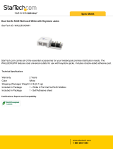
Figure 8: RJ45 Keystone socket
1 – Patch cable inlet
2 – Latch
3 – Installation cable inlet
1
5
4
3
2

18
Installation MIPP
Release
06
04/2019
The following cable types can be used:
Cat 5E (shielded and unshielded)
Cat 6 (shielded and unshielded)
Cat 6A (shielded and unshielded)
Cat 7 (shielded)
The following plug types can be used:
RJ45 plug

Installation MIPP
Release
06
04/2019
19
2Installation
The device has been developed for practical application in a harsh industrial
environment.
The following sequence has proven itself in practice during installation:
Unpacking the package and checking the content
Installing the modules
Removing the modules from the casing
Install the installation cable on the modules
Mount modules in the casing
Mount device on the DIN rail
Connecting patch cables
2.1 Checking the package contents
Check whether the package includes all items named in the section
“Scope of delivery” on page 25.
Check the individual parts for transport damage.
2.2 Installing modules
You will receive the device with modules pre-installed according to your
order.
You require the following tools (not included in the delivery):
Cross-tip screwdriver
Strip tool
Splicer (with F/O cables)
Note: Observe the minimum bend radius provided by the cable
manufacturer.

20
Installation MIPP
Release
06
04/2019
2.2.1 Removing the module from the casing
Proceed as follows:
Loosen the 2 fixed screws on the front of the module and pull the module
forward out of the casing.
Figure 9: Removing the module
2.2.2 Installation of installation cables on LC, SC, ST and
E-2000TM modules
Proceed as follows:
Loosen the cable gland.
Run the installation cable trough the cable gland and into the module.
Remove the jacket from the installation cable on a sufficient length for
splicing.
When using a double module: Install 12 fibers on both sides.
Tighten the cable gland.
Fix the strain relief fixture.
Note: Follow the safety instructions of the splicer manufacturer.
Note: When performing fusion splicing, we recommend to use heat shrink
protectors with a length of 0.98 in to 1.38 in (25 mm to 35 mm) and a
diameter of 0.05 in or 0.10 in (1.3 mm or 2.5 mm) after shrinkage.
/