Millerfi
October
1990
FORM:
OM-871
E
ffective
With
Style
No.
JD-23
MODEL:
RDC-IW-1
RDC-IW-2
OWNERS
MANUAL
IMPORTANT:
Read
and
understand
the
entire
contents
of
both
this
manual
and
the
power
source
manual
used
with
this
unit,
with
special
emphasis
on
the
safety
material
throughout
both
manuals,
before
installing,
operating,
or
maintaining
this
equipment.
This
unit
and
these
instructions
are
for
use
only
by
persons
trained
and
experienced
in
the
safe
operation
of
welding
equip
ment.
Do
not
allow
untrained
persons
to
install,
operate,
or
maintain
this
unit.
Contact
your
distributor
if
you
do
not
fully
understand
these
instructions.
MILLER
ELECTRIC
Mfg.
Co.
A
Miller
Group
U~.,
Company
P.O.
Box
1079
Appleton,
WI
54912
USA
Tel.
414-734.9821
SA-094
539
PRINTED
IN
U.S.A.

I
J
LIMITED
WARRANTY
EFFECTIVE:
AUGUST
6,
1990
This
warranty
supersedes
all
previous
MILLER
warranties
and
is
exclusive
with
no
other
guarantees
or
warranties
expressed
or
implied.
LIMITED
WARRANTY
Subject
to
the
terms
and
conditions
hereof.
MILLER
Electric
Mfg.
Co..
Appleton.
Wisconsin
war
rants
to
its
Distributor/Dealer
that
all
new
and
unused
Equipment
furnished
by
MILLER
is
free
from
detect
in
workmanship
and
material
as
of
the
time
and
place
of
delivery
by
MILLER.
No
warranty
is
made
by
MILLER
with
respect
to
engines,
trade
accessories
or
other
items
manufactured
by
others.
Such
engines,
trade
accessories
and
other
items
are
sold
subject
to
the
warranties
of
their
respective
manumacturers,
if
any.
All
engines
are
warrantied
by
their
manufacturer
for
two
years
from
date
of
original
purchase.
except
Deutz
engines
which
have
a
one
year.
2000
hour
warranty.
Except
as
specified
below.
MILLERs
warranty
does
not
apply
to
components
having
normal
useful
life
ot
less
man
one
II)
year.
such
as
spot
welder
tips,
relay
and
contactor
points,
MILLERMATIC
parts
that
come
in
contact
with
the
welding
wire
including
nozzles
and
nozzle
insulators
where
failure
does
not
result
from
defect
in
workmanship
or
material.
MILLER
shall
be
required
to
honor
warranty
claims
on
war
ranted
Equipment
in
the
event
of
failure
resulting
from
a
defect
within
the
following
periods
from
the
date
of
delivery
of
Equipment
to
the
original
user:
1.
Arc
welders,
power
sources.
robots,
and
1
year
components
2.
Load
banks
1
year
3.
Original
main
power
rectifiers
3
years
(labor
1
year
only)
4.
All
welding
guns.
feeder/guns
and
torches
.
.
90
days
5.
All
other
MILLERMATIC
Feeders
1
year
6.
Replacement
or
repair
parts.
exclusive
of
tabor
60
days
7.
Batteries
6
months
provided
that
MILLER
is
notified
in
writing
within
thirty
30)
days
at
the
date
of
such
failure.
As
a
matter
of
general
policy
only.
MILLER
may
honor
claims
submitted
by
the
original
user
within
the
foregoing
periods.
In
the
case
of
MILLERs
breach
of
warranty
or
any
other
duty
with
respect
to
the
quality
of
any
goods.
the
exclusive
remedies
therefore
shall
be.
at
MILLERs
option
li)
repair
or
12)
replace
ment
or.
where
authorized
in
writing
by
MILLER
in
appropriate
cases.
(3)
the
reasonable
cost
of
repair
or
replacement
at
an
authorized
MILLER
service
station
or
4)
payment
of
or
credit
for
the
purchase
price
(less
reasonable
depreciation
based
upon
actual
use)
upon
return
of
the
goods
at
Customers
risk
and
expense.
MILLERs
option
of
repair
or
replacement
will
be
FOB..
Factory
at
Appleton.
Wisconsin.
or
FOB.
at
a
MILLER
authorized
service
facility.
therefore.
no
compensation
for
transportation
costs
of
any
kind
will
be
allowed.
Upon
receipt
of
notice
of
apoarent
defect
or
?ajlure.
MILLER
shall
instruct
the
ciaimant
on
the
warranty
ciairn
oroceaures
to
oe
followed.
ANY
EXPRESS
WARRANTY
NOT
PROVIDED
HEREIN
AND
ANY
IMPLIED
WARRANTY.
GUARANTY
OR
REPRE
SENTATION
AS
TO
PERFORMANCE.
AND
ANY
REMEDY
FOR
BREACH
OF
CONTRACT
WHICH.
BUT
FOR
THIS
PROVISION.
MIGHT
ARISE
BY
IMPLICATION.
OPERATION
OF
LAW.
CUSTOM
OF
TRADE
OR
COURSE
OF
DEALING.
INCLUDING
ANY
IMPLIED
WARRANTY
OF
MERCHAN
TABILITY
OR
OF
FITNESS
FOR
PARTICULAR
PURPOSE.
WITH
RESPECT
TO
ANY
AND
ALL
EQUIPMENT
FURNISHED
BY
MILLER
IS
EXCLUDED
AND
DISCLAIMED
BY
MILLER.
EXCEPT
AS
EXPRESSLY
PROVIDED
BY
MILLER
IN
WRITING.
MILLER
PRODUCTS
ARE
INTENDED
FOR
ULTIMATE
PURCHASE
SY
COMMERCIAL
INDUSTRIAL
USERS
AND
FOR
OPERATION
BY
PERSONS
TRAINED
AND
EXPERIENCED
IN
THE
USE
AND
MAINTENANCE
OF
WELDING
EQUIPMENT
AND
NOT
FOR
CONSUMERS
OR
CONSUMER
USE.
MILLERS
WARRANTIES
DO
NOT
EXTEND
TO.
AND
NO
RESELLER
IS
AUTHORIZED
TO
EXTEND
MILLERS
WARRANTIES
TO.
ANY
CONSUMER.
UI:

ERRATA
SHEET
After
this
manual
was
printed,
refinements
In
equipment
design
occurred.
This
sheet
lists
exceptions
to
data
appearing
later
In
this
manual.
AMENDMENT
TO
SECTION
2-
INSTALLATION
Amend
Figure
2-2.
RDC-IW-1
Installation
With
Wire
Feeder
INTELLIWELD
POWER
SOURCE
TA-093
977-A
115
VAC/Contactor
RDC4W-1
Rear
View
Connected
To
Motor
Digital
Wire
Feeder
RDC-IW-1
Front
View
Figure
2-2.
RDC-IW-1
Installation
With
Wire
Feeder

Amend
Figure
2-3.
RDC-IW-2
Installation
With
Wire
Feeder
Figure
2-3.
RDC-IW-2
Installation
With
Wire
Feeder
Feeder
115
VAC
TA-093
978-A
Amend
heading
numbers
for
Figure
3-3
and
Figure
3-4
to
read
Figure
2-4
and
Figure
2-5.
AMENDMENT
TO
SECTION
4
SEQUENCE
OF
OPERATION
Add
the
following
WARNING
at
beginnings
of
Sections
4-1,
4-2,
4-3,
4-4,
and
4-5:
a
WARNING:
USING
BOTH
POSITIVE
(+)
WELD
OUTPUT
TERMINALS
at
same
time
can
cause
seri
ous
electric
shock
and
arcing
hazards.
Do
not
use
both
positive
(+)
weld
output
terminals
at
the
same
time.
Read
welding
power
source
Owners
Manual
for
additional
in
formation.
INTELLIWELD
POWER
SOURCE
115
VAC/Conlactor
Digital
Wire
Feeder
OM-871
Page
2

OU.871
.
l~l9O
RECEIVING-HANDLING
Before
unpacking
equipment,
check
carton
for
any
dam-
Use
the
following
spaces
to
record
the
Model
Designa
age
that
may
have
occurred
during
shipment.
File
any
tion
and
Serial
or
Style
Number
of
your
unit.
The
infor
claims
for
loss
or
damage
with
the
delivering
carrier.
mation
is
located
on
the
data
card
or
the
nameplate.
Assistance
for
filing
or
settling
claims
may
be
obtained
from
the
distributor
and/or
the
equipment
manufactur-
Model
________________________________________
ers
Transportation
Department.
Senal
or
Style
No.
____________________
When
requesting
information
about
this
equipment,
al
ways
provide
the
Model
Description
and
Serial
or
Style
Date
of
Purchase
_____________________
Number.
TABLE
OF
CONTENTS
Section
No.
Page
No.
SECTION
1
-
SAFETY
PRECAUTIONS
AND
SIGNAL
WORDS
1-1.
General
Information
And
Safety
1
1-2.
Safety
Alert
Symbol
And
Signal
Words
1
SECTION
2
SPECIFICATIONS
2-1.
Description
1
SECTION
3-INSTALLATiON
OR
RELOCATION
Diagram
3-1.
RDC-lW-1
Installation
With
Wire
Feeder
2
Diagram
3-2.
RDC-lW-2
Installation
With
Dual
Wire
Feeder
3
Diagram
3-3.
Output
Connections
For
Shielded
Metal
Arc
Welding
(SMAW)
(Reverse
Polarity)
Without
Wire
Feeder
3
Diagram
3-4.
Output
Connections
For
Gas
Tungsten
Arc
Welding
(GTAW)
(Straight
Polarity)
Without
Wire
Feeder
3
3-1.
Installation
Of
Remote
Control
4
3-2.
115
Volt
AC
Connection
To
The
Wire
Feeder
4
3-3.
Output
Control
Connection
4
3-4.
115
VAC
Contactor
Connection
To
Welding
Power
Source
4
3-5.
Switching
Relay
Connection
(RDC-IW-2
Models
Only)
4
3-6.
Remote
Control
Receptacles
4
SECTION
4-
OPERATOR
CONTROLS
4-1.
Volts
Control
5
4-2.
Amps
Control
5
4-3.
Volts/Amps
Display
Select
Switch
And
Indicating
Lights
5
4-4.
Remote
Control
Switch(es)
5
4-5.
CC/CP
Selector
Switch
5
4-6.
Arc
Control
5
4-7.
Contactor
Switch
6
4-8.
Digital
Display
6

Section
No.
Page
No.
SECTION
5-
SEQUENCE
OF
OPERATION
5-1.
Gas
Metal
Arc
And
Flux
Cored
Arc
Welding
(GMAW
And
FCAW)
6
5-2.
Shielded
Metal
Arc
Welding
(SMAW)
7
5-3.
Submerged
Arc
Welding
(SAW)
7
5-4.
Gas
Tungsten
Arc
Welding
(GTAW)
8
5-5.
Air
Carbon
Arc
Cutting
And
Gouging
(AAC)
8
5-6.
Shutting
Down
8
SECTION
6
MAINTENANCE
AND
TROUBLESHOOTING
6-1.
Routine
Maintenance
9
6-2.
Troubleshooting
9
SECTION
7-
ELECTRICAL
DIAGRAMS
Diagram
7-1.
Circuit
Diagram
For
RDC-IW-1
Models
11
Diagram
7-2.
Circuit
Diagram
For
RDC-IW-2
Models
12
Diagram
7-3.
Wiring
Diagram
For
RDC-IW-1
Models
13
Diagram
7-4.
Wiring
Diagram
For
RDC-lW-2
Models
14
SECTION
8
PARTS
LIST
Figure
8-1.
Main
Assembly
16
Figure
8-2.
Circuit
Card,
Relay
18
LIST
OF
CHARTS
AND
TABLES
Table
6-1.
Maintenance
Schedule
9
Table
6-2.
Troubleshooting
10

SECTION
1
SAFETY
PRECAUTIONS
AND
SIGNAL
WORDS
1.1.
GENERAL
INFORMATION
AND
SAFETY
A.
General
Information
presented
in
this
manual
and
on
various
la
bels,
tags,
and
plates
on
the
unit
pertains
to
equipment
design,
installation,
operation,
maintenance,
and
troubleshooting
which
should
be
read,
understood,
and
followed
for
the
safe
and
effective
use
of
this
equipment.
The
nameplate
of
this
unit
uses
international
symbols
for
labeling
the
front
panel
controls.
The
symbols
also
ap
pear
at
the
appropriate
section
in
the
text.
B.
Safety
The
installation,
operation,
maintenance,
and
trouble
shooting
of
arc
welding
equipment
requires
practices
and
procedures
which
ensure
personal
safety
and
the
safety
of
others.
Therefore,
this
equipment
is
to
be
in
stalled,
operated,
and
maintained
only
by
qualified
per
sons
in
accordance
with
this
manual
and
all
applicable
codes
such
as,
but
not
limited
to,
those
listed
at
the
end
of
Section
1
Safety
Rules
For
Operation
Of
Arc
Weld-
ing
Power
Source
in
the
welding
power
sources
Owners
Manual.
1-2.
SAFETY ALERT
SYMBOL
AND
SIGNAL
WORDS
The
following
safety
alert
symbol
and
signal
words
are
used
throughout
this
manual
to
call
attention
to
and
iden
tify
different
levels
of
hazard
and
special
instructions.
This
safety
alert
symbol
is
used
with
the
signal
words
WARNING
and
CAUTION
to
call
atten
tion
to
the
safety
statements.
a
WARNING
statements
identify
procedures
or
practices
which
must
be
followed
to
avoid
seri
ous
personal
injury
or
loss
of
life.
a
CAUTION
statements
identify
procedures
or
practices
which
must
be
followed
to
avoid
minor
personal
injury
or
damage
to
this
equipment.
IMPORTANT
statements
identify
special
instructions
necessary
for
the
most
efficient
operation
of
this
equip
ment.
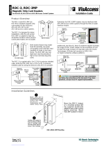
IMPORTANT:
RDC-IW-2
mode/illustrated.
Overall
dimen
sions
same
for
ROC-!
W-
I
models.
2-1.
DESCRIPTION
This
unit
is
a
remote
digital
control
for
the
INTELLI
WELD
welding
power
source.
When
properly
connected
to
the
welding
power
source,
this
unit
provides
arc
con
trol,
contactor
control,
voltage/amperage
control,
and
CC/CP
(constant
currentlconstant
potential
or
voltage)
selection.
The
RDC-IW-1
models
allow
presetting
of
voltage
or
current
parameters
for
a
single
digital
wire
feeder
or
one
side
of
a
dual
digital
wire
feeder.
RDC-lW-2
models
pro
vide
preset
voltage
or
current
parameters
for
both
sides
of
a
dual
wire
feeder.
The
RDC-lW
displays
the
actual
value
of
the
selected
parameter
upon
arc
initiation.
The
remote
digital
control
operates
on
115
VAC,
50/60
Hertz
and
draws
0.5
amps.
a
SECTION
2
SPECIFICATIONS
11-3/4
in.
(298
mm>
10-1/2
in.
(267
mm)
Figure
2-1.
Dimensions
SB.094
539
OM.871
Page
1

SECTION
3
INSTALLATION
OR
RELOCATION
*flDC.1w2
Models
Only.
115
VAClContactor
Receptacle
S0494
Connected
To
Motor
115
VAC/Contactor
Feeder
115
VAC
Diagram
3-1.
RDC-IW-1
Installation
With Wire
Feeder
~Feeder115VAC
Cord
*switching
Relay
Cord
Figure
3-1.
Rear
Panel
View
INTELLIWELD
POWER
SOURCE
Output
Control
Rear
View
Digital
Wire
Feeder
RDC-IW.1
El
0
Front
View
Digital
Wire
Feeder
S
0483
OM.871
Page
2

INTELLIWELD
POWER
SOURCE
Connected
Motor
Diagram
3-2.
RDC-IW-2
Installation
With
Dual
Wire
Feeder
115
VAC/Contactor
Feeder
115
VAC
Gun
Trigger
S-0484
S0485
Diagram
3-3.
Output
Connections
For
Shielded
Metal
Arc
Welding
(SMAW)
(Reverse
Polarity)
Without
Wire
Feeder
S
.0486
Diagram
3-4.
Output
Connections
For
Gas
Tungsten
Arc
Welding
(GTAW)
(Straight
Polarity)
Without
Wire
Feeder
Output
Control
Digital
Dual
Wire
Feeder
115
VAC/Contactor
INTELLIWELD
POWER
SOURCE
Output
Control
RDC.IW-1
Shown
(Connections
Same
For
RDC.IW.2)
115
VAC/Contactor
/
RDC-IW-1
Shown
(Connections
Same
For
RDC.IW.2)
OM.871
Page
3

a
WARNING:
ELECTRIC
SHOCK
can
kill.
Do
not
touch
live
electrical
parts.
Shut
down
welding
power
source
and
wire
feeder,
and
disconnect
input
power
employ
ing
lockout/tagging
procedures
before
in
specting
or
installing.
Lockout/tagging
procedures
consist
of
pad
locking
line
disconnect
switch
in
open
position,
removing
fuses
from
fuse
box,
or
shutting
off
and
red-tagging
circuit
breaker
or
other
disconnect
ing
device.
3-1.
INSTALLATION
OF
REMOTE
CONTROL
The
remote
control
can
be
mounted
on
top
of
a
wire
feeder.
To
install
remote
control,
proceed
as
follows:
1.
Loosen
the
four
wrapper
screws
on
the
top
of
the
feeder
control
box.
2.
Place
remote
control
on
top
of
wire
feeder
control
box
with
front
panels
facing
in
the
same
direction.
3.
Position
control
so
that
wrapper
slots
correspond
to
feeder
control
box
screws.
4.
Slide
control
down
onto
screws.
5.
Tighten
wrapper
screws.
3-2.
115
VOLT
AC
CONNECTION
TO
THE
WIRE
FEEDER
(Figure
3-1
And
Diagrams
3-1
And
3-2)
Connect
four-socket
plug
from
rear
of
remote
control
to
four
pin
receptacle
on
rear
of
wire
feeder.
Rotate
collar
clockwise.
3-3.
OUTPUT
CONTROL
CONNECTION
(Figure
3-1
And
Diagrams
3-1
And
3-2)
Connect
ten-socket
plug
on
supplied
output
control
cord
to
ten-pin
receptacle
on
rear
of
the
remote
control.
Ro
tate
threaded
collar
fully
clockwise.
Connect
remaining
end
of
cord
to
REMOTE
10
recepta
cle
on
the
welding
power
source.
Rotate
threaded
collar
fully
clockwise.
3-4.
115
VAC
CONTACTOR
CONNECTION
TO
WELDING
POWER
SOURCE
(Figure
3-1
And
Diagrams
3-1
And
3-2)
Make
connections
between
remote
control,
wire
feeder,
and
welding
power
source
as
follows:
1.
Connect
ten-socket
plug
on
supplied
output
con
trol
cord
to
ten-pin
receptacle
on
rear
of
the
re
mote
control.
Rotate
threaded
collar
fully
clock
wise.
2.
Locate
115
volts/contactor
control
cable
supplied
with
wire
feeder.
3.
Connect
115
volts/contactor
cord
to
matching
re
ceptacle
on
rear
of
wire
feeder
as
follows:
align
keyways,
insert
plug,
and
roate
threaded
collar
fully
clockwise.
4.
Route
remaining
end
of
115
volts/contactor
cord
to
REMOTE
14
receptacle
on
welding
power
source.
Connect
plug
to
receptacle
as
follows:
align
keyways,
insert
plug,
and
roate
threaded
collar
fully
clockwise.
IMPORTANT:
If
the
supplied
cords
do
not
match
the
wire
feeder
and/or
welding
power
source
receptacles,
obtain
the
necessaiy
adapter
cord
from
your
welding
equipment
distributor.
3-5.
SWITCHING
RELAY
CONNECTION
(RDC
lW-2
Models
Only)
(Figure
3-1
And
Diagram
3-2)
Connect
four-contact
connector
from
rear
of
remote
control
to
four-contact
connector
on
rear
of
dual
wire
feeder.
3-6.
REMOTE
CONTROL
RECEPTACLES
(Figure
4-1)
The
remote
control
receptacle(s)
is
provided
on
the
re
mote
control
front
panel
for
connecting
an
optional
digi
tal
dual
schedule
control.
Use
an
interconnecting
cord
to
connect
six-socket
receptacle
on
front
of
the
remote
control
to
six-pin
receptacle
on
the
Digital
Dual
Schedule
Control.
IMPORTANT:
When
using
a
Digital
Dual
Schedule
Con
trol,
place
appropriate
STANDARD/REMOTE
switch
in
the
REMOTE
position.
OM.871
Page
4

SECTION
4-
OPERATOR
CONTROLS
Volts
Control
Digital
Display
Amps
Control
Remote
Control
Switch
Ret.
SA.094
539
Figure
4-1.
Front
Panel
View
(RDC-IW-2
Model
Illustrated)
4-1.
VOLTS
CONTROL
(Figure
4-1)
The
VOLTS
control
is
a
ten-turn
potentiometer
which
presets
weld
voltage
for
constant
voltage
applications.
Rotating
the
control
clockwise
increases
voltage.
This
control
is
disabled
when
the
CCICP
Selector
switch
is
in
the
CC
position.
IMPORTANT:
The
VOLTS
control
can
be
adjusted
while
welding.
4-2.
AMPS
CONTROL
(FIgure
4-1)
The
AMPS
control
is
a
ten-turn
potentiometer
which
pre
sets
weld
amperage
for
constant
current
applications.
Rotating
the
control
clockwise
increases
amperage.
This
control
is
disable
when
the
CC/CP
Selector
switch
is
in
the
CP
position.
IMPORTANT:
The
AMPS
control
can
be
adjusted
while
welding.
4-3.
VOLTS/AMPS
DISPLAY
SELECT
SWITCH
AND
INDICATING
LIGHTS
(Figure
4-1)
This
switch
is
used
to
select
either
volts
or
amps
to
be
shown
on
the
digital
display.
When
the
switch
is
in
the
VOLTS
(down)
position,
volts
are
displayed,
and
the
volts
indicating
light
comes
on.
When
the
switch
is
in
the
AMPS
position,
amps
are
displayed,
and
the
amps
indi
cating
light
comes
on.
IMPORTANT:
The
VOLTS/AMPS
Switch
can
be
changed
while
welding.
4-4.
REMOTE
CONTROL
SWITCH(es)
(Figure
4-1)
The
Remote
Control
switch(es)
is
provided
for
selecting
single
scheduling
via
the
RDC-IW
or
dual
scheduling
via
an
optional
Digital
Dual
Schedule
Control.
The
Remote
Control
switch
must
be
in
the
STANDARD
position
to
preset
welding
parameters
at
the
RDC-IW.
The
Remote
Control
switch
must
be
in
the
REMOTE
position
to
pre
set
welding
parameters
from
the
Digital
Dual
Schedule
control
and
to
dual
schedule
welding
conditions.
4-5.
CC/CP
SELECTOR
SWITCH
(Figure
4-1)
The
CC/CP
selector
switch
allows
selection
of
CC
(con
stant
current),
CP
(constant
potential
or
voltage)
output
from
the
welding
power
source.
The
CC
position
provides
a
constant
current
output
spe
cifically
designed
for
Shielded
Metal
Arc
(SMAW)
and
Gas
Tungsten
Arc
(GTAW)
Welding
processes.
The
CC
position
is
also
normally
used
for
Air
Carbon
Arc
Cutting
(AAC)
and
gouging
processes.
The
CP
position
provides
a
constant
voltage
output
de
signed
for
wire
feeding
applications
such
as
Gas
Metal
Arc
(GMAW),
Flux
Cored
Arc
(FCAW),
or
Submerged
Arc
(SAW)
Welding.
4-6.
ARC
CONTROL
(Figure
4-1)
IMPORTANT:
The
ARC
CONTROL
potentiometer
is
disabled
in
the
CP
(Constant
Potential)
and
pulsed
modes.
The
ARC
CONTROL
potentiometer
provides
variable
selection
of
short-circuit
current
to
suit
individual
welding
conditions.
Rotating
this
control
clockwise
causes
the
current
to
increase
as
the
short-circuit
condition
is
ap
proached.
When
this
control
is
set
at
some
value
above
0,
the
current
begins
to
increase
when
arc
voltage
drops
below
20
volts.
When
the
control
is
set
at
10,
the
short-circuit
current
is
considerably
higher
than
normal
welding
current
(see
welding
power
source
volt-ampere
curve
for
CC
mode).
Control
Arc
Control
Contactor
CC/C
P
Switch
Volts/Amps
5witch
Remote
Control
Receptacle
OM-871
Page
5

This
provides
extra
current
for
arc
starting
in
out-of-posi
tion
welds
as
well
as
for
certain
types
of
electrodes.
When
the
control
is
set
at
0,
short-circuit
current
is
the
same
as
normal
welding
current.
The
0
position
provides
current
characteristics
associated
with
the
Gas
Tung
sten
Arc
Welding
(GTAW)
process.
When
the
control
is
set
at
5,
short-circuit
current
is
ap
proximately
half
that
of
the
1
0
position
but
still
higher
than
normal
welding
current.
The
5
position
provides
a
moderate
current
increase
for
arc
starting
necessary
for
certain
types
of
electrodes
and
applications.
Select
a
setting
best
suited
for
the
application.
The
Arc
Control
indicating
light
turns
on
when
the
CC/
CP
Selector
switch
is
in
the
CC
position
indicating
that
the
ARC
CONTROL
is
active.
IMPORTANT:
The
ARC
CONTROL
can
be
adjusted
while
welding.
4-7.
CONTACTOR
SWITCH
(Figure
4.1)
a
WARNING:
ELECTRIC
SHOCK
can
kill.
Do
not
touch
live
electrical
parts.
Do
not
touch
the
weld
output
terminals
when
the
contactor
is
energized.
Do
not
touch
electrode
(or
gun
wire)
and
work
clamp
at
the
same
time.
If
the
Remote
Control
CONTACTOR
switch
is
in
the
ON
position,
open-circuit
voltage
will
be
present
at
the
out
put
terminals
whenever
the
welding
power
source
POWER
switch
ON
button
is
pressed.
IMPORTANT:
Although
the
term
CONTACTOR
is
used
on
the
nameplate
and
throughout
this
manual,
the
weld
output
is
not
switched
on
or
off
by
a
physical
secondary
contactor;
rather,
the
weld
output
is
controlled
by
solid-
state
circuitry
in
the
welding
power
source.
If
contactor
control
by
means
of
a
wire
feeder
is
desired,
place
the
Remote
Control
CONTACTOR
switch
in
the
OFF
position.
Open-circuit
voltage
will
be
present
at
the
weld
output
terminals
whenever
the
gun
switch
is
closed.
4-8.
DIGITAL
DISPLAY
(Figure
4-1)
When
functioning
as
a
voltmeter,
the
digital
display
indi
cates
voltage
to
the
nearest
tenth
of
a
volt
while
welding
and
preset
voltage
when
unit
is
idling.
When
functioning
as
an
ammeter,
the
digital
display
indi
cates
weld
amperage
to
the
nearest
ampere
while
weld
ing
and
preset
amperage
when
unit
is
idling.
SECTION
5
SEQUENCE
OF
OPERATION
f~
WARNING:
ELECTRIC
SHOCK
can
kill;
MOVING
PARTS
can
cause
serious
injury;
IMPROPER
AIR
FLOW
AND
EXPOSURE
TO
ENVIRONMENT
can
damage
internal
parts.
Keep
all
covers
and
panels
in
place
while
op
erating.
Warranty
is
void
if
the
unit
is
operated
with
any
portion
of
the
outer
enclosure
removed.
ARC
RAYS,
SPARKS,
AND
HOT
SURFACES
can
burn
eyes
and
skin;
NOISE
can
damage
hearing.
Wear
correct
eye,
ear,
and
body
protection.
FUMES
AND
GASES
can
seriously
harm
your
health.
Use
enough
ventilation
to
keep
fumes
and
gases
from
the
breathing
zone.
WELDING
WIRE
can
cause
puncture
wounds.
Do
not
point
gun
toward
any
part
of
the
body
or
other
personnel.
HOT
METAL,
SPATTER,
AND
SLAG
can
cause
fire
and
burns.
Watch
for
fire.
Have
a
fire
extinguisher
nearby
and
know
how
to
use
it.
MAGNETIC
FIELDS
FROM
HIGH
CURRENTS
can
affect
pacemaker
operation.
Wearers
should
consult
with
their
doctor
be
fore
going
near
arc
welding,
gouging,
or
spot
welding
operations.
See
Section
1
Safety
Rules
For
Operation
Of
Arc
Welding
Power
Source
in
the
welding
power
source
Owners
Manual.
5-1.
GAS
METAL
ARC
AND
FLUX
CORED
ARC
WELDING
(GMAW
AND
FCAW)
AA
WARNING:
Read
and
follow
safety
informa
tion
at
beginning
of
entire
Section
5
before
proceeding.
WARNING:
USING
BOTH
POSITIVE
(+)
WELD
OUTPUT
TERMINALS
at
same
time
can
cause
serious
electric
shock
and
arcing
hazards.
Do
not
use
both
positive
(+)
weld
output
termi
nals
at
the
same
time.
Read
welding
power
source
Owners
Manual
for
additional
information.
Install
and
connectwelding
power
source
accord
ing
to
its
Owners
Manual.
2.
Install
Remote
Control
as
instructed
in
Section
3.
a
OM.871
Page
6

3.
Install
and
connect
wire
feeder
according
to
its
Owners
Manual.
4.
Wear
dry
insulating
gloves
and
clothing.
5.
Connect
work
clamp
to
clean,
bare
metal
at
workpiece.
6.
Select
proper
welding
wire.
7.
Depress
welding
power
source
POWER
switch
ON
button.
8.
Place
Remote
Output
Control
switch
on
the
weld
ing
power
source
in
the
REMOTE
position.
9.
Place
remote
control
switch
on
the
A
DC-lW
con
trol
in
the
STANDARD
position.
10.
Place
CC/CP
Selector
switch
in
CP
position.
11.
Place
CONTACTOR
switch
in
OFF
position.
12.
Place
VOLTS/AMPS
switch
in
the
VOLTS
posi
tion.
13.
Preset
VOLTS
control
to
desired
weld
voltage
setting
(see
Section
4-1).
14.
Thread
welding
wire
as
instructed
in
wire
feeder
Owners
Manual.
15.
Make
ay
required
adjustments
to
wire
feeder.
IMPORTANT:
If
an
optional
Digital
Dual
Schedule
con
trol
is
used,
place
Remote
Control
switch
in
the
RE
MOTE
position
and
set
the
welding
parameters
for
the
second
schedule
on
the
Dual
Schedule
Control.
16.
Turn
on
shielding
gas
supply,
if
applicable.
17.
Wear
welding
helmet
with
proper
filter
lens
ac
cording
to
ANSI
Z49.1.
18.
Begin
welding.
5-2.
SHIELDED
METAL
ARC
WELDING
(SMAW)
a
WARNING:
Read
and
follow
safety
informa
tion
at
beginning
of
entire
Section
5
before
proceeding.
WARNING:
USING
BOTH
POSITIVE
(+)
WELD
OUTPUT
TERMINALS
at
same
time
can
cause
serious
electric
shock
and
arcing
hazards.
Do
not
use
both
positive
(.4.)
weld
output
termi
nals
at
the
same
time.
Read
we/ding
power
source
Owners
Manual
for
additional
information.
1.
Install
and
connect
welding
power
source
accord
ing
to
its
Owners
Manual.
2.
Install
Remote
Control
as
instructed
in
Section
3.
3.
Install
and
connect
wire
feeder
according
to
its
Owners
Manual.
4.
Wear
dry
insulating
gloves
and
clothing.
5.
Connect
work
clamp
to
clean,
bare
metal
at
workpiece.
6.
Select
proper
electrode.
7.
Depress
welding
power
source
POWER
switch
ON
button.
8.
Place
Remote
Output
Control
switch
on
the
weld
ing
power
source
in
the
REMOTE
position.
9.
Place
remote
control
switch
on
the
RDC-IW
con
trol
in
the
desired
position
(see
Section
4-4).
Place
CC/CP
Selector
switch
in
CC
position.
Place
CONTACTOR
switch
in
ON
position.
Place
VOLTS/AMPS
switch
in
the
AMPS
posi
tion.
13.
Preset
AMPS
Control
to
desired
weld
amperage
setting
(see
Section
4-2).
14.
Place
ARC
CONTROL
to
desired
position
(see
Section
4-6).
15.
Wear
welding
helmet
with
proper
filter
lens
ac
cording
to
ANSI
Z49.1.
16.
Insert
electrode
into
electrode
holder.
17.
Begin
welding.
5-3.
SUBMERGED
ARC
WELDING
(SAW)
a
WARNING:
Read
and
follow
safety
informa
tion
at
beginning
of
entire
Section
5
before
proceeding.
a
WARNING:
USING
BOTH
POSITIVE
(+)
WELD
OUTPUT
TERMINALS
at
same
time
can
cause
serious
electric
shock
and
arcing
hazards.
Do
not
use
both
positive
(+)
weld
output
termi
nals
at
the
same
time.
Read
welding
power
source
Owners
Manual
for
additional
in
formation.
1.
Install
and
connect
welding
power
source
accord
ing
to
its
Owners
Manual.
2.
Install
Remote
Control
as
instructed
in
Section
3.
3.
Install
and
connect
wire
feeder
according
to
its
Owners
Manual.
4.
Install
flux
system
according
to
its
Owners
Man
ual.
5.
Wear
dry
insulating
gloves
and
clothing.
6.
Connect
work
clamp
to
clean,
bare
metal
at
workpiece.
7.
Depress
welding
power
source
POWER
switch
ON
button.
8.
Place
remote
control
switch
on
the
RDC-IW
con
trol
in
the
desired
position
(see
Section
4-4).
9.
Place
CC/CP
Selector
switch
in
CP
position.
10.
Place
CONTACTOR
switch
in
OFF
position.
11.
Place
VOLTS/AMPS
switch
in
the
VOLTS
posi
tion.
12.
Preset
VOLTS
control
to
desired
weld
voltage
setting
(see
Section
4-1).
10.
11.
12.
a
OM-871
Page
7

13.
Wear
safety
goggles
with
correct
filter
shade
ac
cording
to
ANSI
Z49.1.
14.
Make
any
required
adjustments
to
wire
feeder.
15.
Turn
on
flux
system.
16.
Begin
welding.
5-4.
GAS
TUNGSTEN
ARC
WELDING
(GTAW)
a
WARNING:
Read
and
follow
safety
informa
tion
at
beginning
of
entire
Section
5
before
proceeding.
WARNING:
USING
BOTH
POSITIVE
(+)
WELD
OUTPUT
TERMINALS
at
same
time
can
cause
serious
electric
shock
and
arcing
hazards.
Do
not
use
both
positive
(.4.)
weld
output
termi
na/s
at
the
same
time.
Read
welding
power
source
Owners
Manual
for
additional
in
formation.
1.
Install
and
connect
welding
power
source
accord
ing
to
its
Owners
Manual.
2.
Install
Remote
Control
as
instructed
in
Section
3.
3.
Install
and
connect
wire
feeder
according
to
its
Owners
Manual.
4.
Install
and
connect
High-Frequency
unit
accord
ing
to
its
Owners
Manual,
if
applicable.
Scratch
start
GTAW
does
not
require
the
use
of
external
high
frequency.
5.
Wear
dry
insulating
gloves
and
clothing.
6.
Connect
work
clamp
to
clean,
bare
metal
at
workpiece.
7.
Select
proper
tungsten
electrode.
8.
Depress
welding
power
source
POWER
switch
ON
button.
9.
Place
remote
control
switch
on
the
RDC-IW
con
trol
in
the
desired
position
(see
Section
4-4).
10.
Place
CC/CF
Selector
switch
in
CC
position.
11.
Place
CONTACTOR
switch
in
ON
position.
12.
Place
VOLTS/AMPS
switch
in
the
AMPS
posi
tion.
13.
Preset
AMPS
control
to
desired
weld
amperage
setting
(see
Section
4-2).
14.
Set
ARC
CONTROL
toO
(zero).
15.
Prepare
tungsten
electrode
according
to
welding
power
source
Owners
Manual,
and
insert
into
torch.
16.
Turn
on
shielding
gas
and
water
supplies
as
appli
cable.
17.
Turn
on
and
adjust
High-Frequency
unit
if
appli
cable.
18.
Wear
welding
helmet
with
proper
filter
lens
ac
cording
to
ANSI
Z49.1.
19.
Begin
welding.
5-5.
AIR
CARBON
ARC
CUTTING
AND
GOUGING
(AAC)
a
WARNING:
Read
and
follow
safety
informa
tion
at
beginning
of
entire
Section
5
before
proceeding.
WARNING:
USING
BOTH
POSITIVE
(+)
WELD
OUTPUT
TERMINALS
at
same
time
can
cause
serious
electric
shock
and
arcing
hazards.
Do
not
use
both
positive
(..)
weld
output
termi
nals
at
the
same
time.
Read
welding
power
source
Owners
Manual
for
additional
information.
1.
Install
and
prepare
welding
power
source
accord
ing
to
its
Owners
Manual.
2.
Install
Remote
Control
as
instructed
in
Section
3.
3.
Connect
compressed
air
supply.
4.
Wear
dry
insulating
gloves
and
clothing.
5.
Connect
work
clamp
to
clean,
bare
metal
at
workpiece.
6.
Select
proper
carbon
electrode.
7.
Depress
welding
power
source
POWER
switch
ON
button.
8.
Place
CC/CP
Selector
switch
in
CC
position.
9.
Place
CONTACTOR
switch
in
ON
position.
10.
Place
VOLTS/AMPS
switch
in
the
AMPS
posi
tion.
11.
Preset
AM
PS
control
to
desired
amperage
setting
(see
Section
4-2).
12.
Set
ARC
CONTROL
to
desired
position
(see
Sec
tion
4-6).
13.
Insert
electrode
into
torch.
14.
Turn
on
air
supply.
15.
Wear
welding
helmet
with
proper
filter
lens
ac
cording
to
ANSI
Z49.1.
16.
Begin
cutting/gouging
process.
5-6.
SHUTTING
DOWN
1.
Stop
welding
or
cutting/gouging
process.
2.
Depress
the
welding
power
source
POWER
switch
OFF
button.
3.
Turn
off
the
shielding
gas
and
water
supplies
if
ap
plicable.
a
WARNING:
HIGH
CONCENTRATION
OF
SHIELDING
GASES
can
harm
health
or
kill.
Shut
off
gas
supply
when
not
in
use.
4.
Turn
off
flux
supply
and
compressed
air
supply
if
applicable.
a
a
OM-871
Page
8

SECTION
6
MAINTENANCE
AND
TROUBLESHOOTING
6-1.
ROUTINE
MAINTENANCE
IMPORTANT:
Every
six
months
inspect
the
labels
on
this
unit
for
legibility.
All
precautionary
labels
must
be
maintained
in
a
clearly
readable
state
and
replaced
when
necessary.
See
Parts
List
for
part
number
of
precautionary
labels.
a
WARNING:
ELECTRIC
SHOCK
can
kill.
Do
not
touch
live
electrical
parts.
Shutdown
welding
power
source,
and
discon
nect
input
power
employing
lockout/tagging
procedures
before
inspecting,
maintaining,
or
servicing.
Lockout/tagging
procedures
Consist
of
pad
locking
line
disconnect
switch
in
open
position,
removing
fuses
from
fuse
box,
or
shutting
off
and
red-tagging
circuit
breaker
or
other
disconnect
ing
device.
MOVING
PARTS
can
cause
serious
injury.
Keep
away
from
moving
parts.
HOT
SURFACES
can
cause
severe
burns.
Allow
cooling
period
before
servicing.
Table
6-1.
Maintenance
Schedule
Frequency*
Maintenance
Every
month.
Units
in
heavy
service
environ
ments:
Check
labels
and
interconnecting
cords.
Every
6
months.
Check
all
labels
(see
IMPORTAN1
block,
Section
6-1)
and
inter
connecting
cords.
*Frequency
of
service
is
based
on
units
operated
40
hours
per
week.
Increase
frequency
of
maintenance
if
usage
exceeds
40
hours
per
week.
Every
six
months,
inspect
all
interconnecting
cords
and
plugs
for
damage
to
the
insulation
jacket.
Repair
or
re
place
the
cord(s)
as
necessary.
6-2.
TROUBLESHOOTING
(Table
6-2)
a
WARNING:
ELECTRIC
SHOCK
can
kill.
Do
not
touch
live
electrical
parts.
Shutdown
welding
powersource,
and
discon
nect
input
power
employing
lockout/tagging
procedures
before
inspecting,
maintaining,
or
servicing.
Lockout/tagging
procedures
consist
of
pad
locking
line
disconnect
switch
in
open
position,
removing
fuses
from
fuse
box,
or
shutting
off
and
red-tagging
circuit
breaker
or
other
disconnect
ing
device.
MOVING
PARTS
can
cause
serious
injury.
Keep
away
from
moving
parts.
HOT
SURFACES
can
cause
severe
burns.
Allow
cooling
period
before
servicing.
Troubleshooting
to
be
performed
only
by
quali
fied
persons.
It
~
assumed
that
the
unit
was
properly
installed
accord
ing
to
Section
3
of
this
manual,
the
operator
is
familiar
with
the
function
of
controls,
the
unit
was
working
prop
erly,
and
that
the
trouble
is
not
related
to
the
welding
process.
The
following
table
is
designed
to
diagnose
and
provide
remedies
for
some
of
the
troubles
that
may
develop
in
this
unit.
Use
this
table
in
conjunction
with
the
circuit
dia
gram
while
performing
troubleshooting
procedures.
If
the
trouble
is
not
remedied
after
performing
these
proce
dures,
contact
the
nearest
Factory
Authorized
Service
Station.
In
all
cases
of
equipment
malfunction,
strictly
follow
the
manufacturers
procedures
and
instructions.
OM-871
Page
9

Table
6-2.
Troubleshooting
TROUBLE
CAUSE
REMEDY
No
display.
Wire
feeder
Power
switch
in
OFF
position.
Energize
wire
feeder.
Digital
meter.
Replace
meter.
Welding
power
source
does
not
deliver
preset
current
and
voltage.
Remote
Control
switch
on
RDC-IW-2
in
REMOTE
position
without
a
digital
Dual
Scheduling
Control
connected.
Place
Remote
Control
switch
in
STANDARD
position
or
connect
a
Digital
Dual
Scheduling
Control.
Remote
Control
switch
on
welding
power
source.
Make
sure
Remote
Control
switch
is
in
REMOTE
position.
Unable
to
preset
voltage;
current
adjustment
available.
VOLTS
control
Ri.
Replace
Ri.
~______________________________
VOLTS/AMPS
Switch
S2.
Replace
S2.
Relay
CR52.
Replace
CR52.
Switch
S5.
Replace
S5.
Unable
to
preset
current;
voltage
adlustment
available.
AMPS
control
R2
(or
R4).
Replace
R2
(or
R4).
VOLTS/AM
PS
switch
S2.
Replace
S2.
Relay
CR52.
Replace
CR52.
Switch
S5.
Replace
S5.
Does
not
display
actual
parameters
while
welding.
115
VAC
connection
to
feeder
improper
or
not
secure.
Check
connection.
Relays
CR50
or
CR54
(RDC-1W-1
models),
or
CR50
or
CR56
(RDC-1W-2
models).
Replace
relay(s).
OM.871
Page
10

SECTION
7-
ELECTRICAL
DIAGRAMS
AC
IN
B
AC
DA
B
C
E
H
C
D
I
Circuit
Diagram
No.
A-093
385
Diagram
7-1.
Circuit
Diagram
For
RDC-IW-1
Models
OM-871
Page
11

AC
IN~
AC
OUT
Diagram
7-2.
Circuit
Diagram
For
RDC-IW-2
Models
Circuit
Diagram
No.
B-093
419-A
A
~
C
CE
F
OM-871
Page
12

SI
PL2
P3
PLG5O
KEYWAY
PCJ
PLG
I
PLG2
248
Diagram
7-3.
Wiring
Diagram
For
RDC-IW-1
Models
PC
I
Wiring
Diagram
No.
SC-i
07
635
GPOUNO

Page is loading ...
Page is loading ...
Page is loading ...
Page is loading ...
Page is loading ...
Page is loading ...
/