Merlin PowerAce MT60EVO Installation And Operating Instructions Manual
- Category
- Garage Door Opener
- Type
- Installation And Operating Instructions Manual
This manual is also suitable for

Owners Copy: SAVE THESE INSTRUCTIONS for future reference
MT120EVO
Sectional Garage Door Opener
Installation and Operating Instructions
This manual contains IMPORTANT SAFETY information
DO NOT PROCEED WITH THE INSTALLATION BEFORE READING THOROUGHLY
gomerlin.com.au
gomerlin.co.nz

1
CONTENTS PAGE
SAFETY INSTRUCTIONS . . . . . . . . . . .1
BEFORE YOU BEGIN . . . . . . . . . . . . . .2
DOOR TYPES . . . . . . . . . . . . . . . . . . . .2
CARTON INVENTORY . . . . . . . . . . . . .3
RAIL SIZES . . . . . . . . . . . . . . . . . . . . . .3
TOOLS REQUIRED . . . . . . . . . . . . . . . .4
HARDWARE PROVIDED . . . . . . . . . . . .4
COMPLETED INSTALLATION . . . . . . . .4
CONTROL PANEL . . . . . . . . . . . . . . . . .5
ASSEMBLY . . . . . . . . . . . . . . . . . . . . . .6
INSTALLATION . . . . . . . . . . . . . . . . .7-10
OPERATE THE MANUAL RELEASE . .10
ADJUSTMENT . . . . . . . . . . . . . . . .11-12
INSTALL THE PROTECTOR
SYSTEM (OPTIONAL) . . . . . . . . . . . . .13
INSTALL WIRELESS WALL
BUTTON . . . . . . . . . . . . . . . . . . . . . . . .14
TIMER TO CLOSE . . . . . . . . . . . . . . . .14
INSTALL WARNING LABELS . . . . . . .15
PARTIAL OPENING FEATURE . . . . . .15
WIRELESS PROGRAMMING . . . . . . .16
USING YOUR OPENER . . . . . . . . . . .17
CARE OF YOUR OPENER . . . . . . . . .17
REPLACE BATTERIES IN
REMOTE . . . . . . . . . . . . . . . . . . . . . . .17
ACCESSORIES . . . . . . . . . . . . . . . . . .18
REPLACEMENT PARTS . . . . . . . . . . .19
TROUBLESHOOTING . . . . . . . . . . 20-21
SPECIFICATIONS . . . . . . . . . . . . . . . .22
WARRANTY . . . . . . . . . . . . . . . . . . . . .23
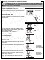
Warning: If your garage has no service entrance door, a E1702M outside quick release must be installed. This
accessory allows manual operation of the garage
door from outside in case of power failure.
Install the wireless wall control (or any additional wall control) in
a location where the garage door is visible, at a height of at
least 1.5 m and out of the reach of children. Do not allow
children to operate push button(s) or transmitter(s). Serious
personal injury from a closing garage door may result from
misuse of the opener.
Permanently fasten the Warning Labels in Prominent Places,
adjacent to Wall Controls and on manual release mechanism as
a reminder of safe operating procedures.
Activate opener only when the door is in full view, free of
obstructions and the opener is properly adjusted. No one
should enter or leave the garage while the door is in motion.
Automatic Door- The door may operate unexpectedly, therefore
do not allow anything to stay in the path of the door.
Do not allow children to play near the door, or with door
controls. Keep remotes away from children.
Disconnect electric power to the garage door opener before
making repairs or removing covers.
If the supply cord is damaged, it must be replaced by the
manufacturer, its service agent or similarly qualified persons in
order to avoid hazard.
This opener should not be installed in a damp or wet space
exposed to weather.
To avoid damage to very light doors (such as fibreglass,
aluminium or steel doors), an appropriate reinforcement should
be added. To do so, contact the door manufacturer.
SAVE THESE INSTRUCTIONS
•Failure tocomplywiththefollowing instructionsmayresultinserious personal injuryor property damage.
• Read and follow all instructions carefully.
• The garage door opener is designed and tested to offer safe service, provided it is installed and operated in strict
accordance with the instructions in this manual.
T
hese safety alert symbols mean WARNING : A possible risk to personal safety or property
damage exists.
Keep garage door balanced. Do not let the garage door
opener compensate for a binding or sticking garage door.
Sticking, binding or unbalanced doors must be repaired
before installing this opener.
Do not wear rings, watches or loose clothing while
installing or servicing a garage door opener. Wear gloves,
safety goggles and suitable protective clothing where
appropriate.
Frequently examine the door installation, in particular
cable, springs and mountings for signs of wear, damage or
imbalance. Do not use if repair or adjustment is needed
since springs and hardware are under extreme tension
and a fault can cause serious personal injury.
To avoid serious personal injury from entanglement,
remove all ropes, chains and locks connected to the
garage door before installing the door opener.
Installation and wiring must be in compliance with your
local building and electrical codes.
The safety reverse system test is very important. Your
garage door MUST reverse on contact with a 40 mm
obstacle placed on the floor. Failure to properly adjust the
opener may result in serious personal injury from a closing
garage door. Repeat the test once a month and make
any necessary adjustments.
This appliance is not intended for use by persons
(including children) with reduced physical, sensory or
mental capabilities, or lack of experience and knowledge,
unless they have been given supervision or instruction
concerning use of the appliance by a person responsible
for their safety.
Use the Manual Release only for the separation of the
carriage from the drive and - if possible - ONLY with the
door closed. Do not use the red handle to push the door
up or pull it down. Operation of the emergency release can
lead to uncontrolled movements of the door, if springs are
weak or broken or if the door is unbalanced. Mount the
release handle of the emergency release at a height less
than 1.8 m from the floor.
After installation, ensure that the parts of the door do
not extend over public footpaths or roads.
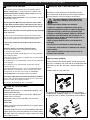
START BY READING THESE IMPORTANT SAFETY INSTRUCTIONS
WARNING!
Merlin recommends that “The Protector System
TM
” be
i
nstalled on all garage door openers. The “Protector
System
TM
” provides an additional measure of safety against
entrapment and is strongly recommended for homeowners
with young children.
“The Protector System
T
M
”must be used for all installations
where the closing force as measured on the bottom of the
door is over 400 N (40 kgf). Excessive force will interfere with
the proper operation of the Safety Reverse System or damage
the garage door.
Installers should ensure that the doors are installed in a
compliant manner as per AS/NZS 60335-2-95.

2
BEFORE YOU BEGIN:
1. Look at the wall and ceiling above the garage door. (The opener and header bracket must be securely fastened to structural
supports.)
2
. Do you have a finished ceiling in your garage? If so, a support bracket and additional fastening hardware (not supplied) may
be required.
3. Do you have an access door in addition to the garage door? If not, model E1702M Outside Quick Release Accessory is
required. This accessory allows manual operation of the garage door from outside in case of power failure.
4. Complete the following test to make sure your garage door is balanced and is not sticking or binding:
• Lift the door about halfway. Release the door. If balanced, it should stay in place, supported entirely by its springs.
• Raise and lower the door to see if there is any binding or sticking, 20 kgf is the absolute maximum allowable force to raise or
lower the door in any position. If your door binds, sticks, or is out of balance, call a trained door technician.
DOOR TYPES
A. Sectional Door with curved track
To suit spring balanced Residential Sectional
doors up to 20 m
2
.
A
1
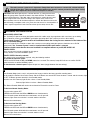
Electrical Connection
A 240 V General Purpose Outlet (GPO) ie. Power Point must be available in close proximity to the powerhead.
This fitting is not part of the Opener hardware and must be supplied by the consumer.
In the event of a power outage or the unit being disconnected from the power source, the door MUST be operated and
supervised so that it completes a full UP and DOWN cycle with no obstructions in place to ensure that the unit
automatically checks that the safety force settings are correct.

1
2
4
5
6
7
8
9
10
11
3
14
12
IMPORTANTSAFETYinformation
TALLATIONBEFOREREADINGTHOROUGHLY
N2966N2966N2966N2966
13
Owners Copy: SAVE THESE INSTRUCTIONS for future reference
MT120EVO
Sectional Garage Door Opener
I
nstallation and Operating Instructions
Thismanual contains IMPORTANT SAFETY information
DONOT PROCEED WITH THE INSTALLATION BEFORE READING THOROUGHLY
N2966N2966N2966N2966
gomerlin.com.au
gomerlin.co.nz
114A3361
ForService Call
InstallationDate
132A2900
RISKOF ENTRAPMENT
RepeatSafety Reverse Test monthly Door
mustreverse on contact with a 40mm obstacle
p
lacedon the floor Make necessary adjustments
AUTOMATICDRIVE:
K
eepaway from the area of the door since it may
o
perateunexpectedly
EMERGENCYRELEASE:
Torelease pull down firmly on the red handle
15
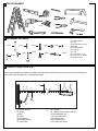
CARTON INVENTORY
(
1) Opener
(2) Premium+ transmitter (2)
(3) Wireless wall control
(4) Curved door arm
(5) Hanging bracket (2)
(6) Rail bracket
(7) Header bracket
(8) Door bracket
(
9) Hardware bag
(10) Rail assembly (separate carton)
(11) C-Rail bracket (2)
(12) Warning labels
(13) Manual
(14) Centre rail brackets (set)
(15) Door bracket
Y
our garage door opener and rail are packed in two seperate cartons. The CyclonePro (MT120EVO) opener carton
contains the opener, its fitting hardware and accessories. The rail carton contains the rail and some hardware.
2
RAIL SIZES AVAILABLE
3
DOOR HEIGHT:
Sectional Doors
CHAIN & RAIL
PART NUMBER:
RAIL LENGTH: CEILING FIXING
POINTS: (standard)
ALTERNATE
FIXING POINT:
Up to 2.4 m 7024 CR5ANZ 3200 mm single piece 3040 mm
3150 mm
From 2.4 - 3.4 m 740 CR5ANZ 1000 mm extension 4040 mm
4150 mm
NOTE: The Ceiling Fixing Point (Standard) is the position of the hanging bracket measured back from the lintel (see
item 1 to 7 of “completed installation”). Also allow 400 mm back from the fixing point for installation of the powerhead
(item 7 to 9 of “completed installation”).
The Alternate Fixing Point will position the hanging bracket between the Powerhead C-Rail brackets, (Item 14 of
“completed installation”) and may line up with a structural support more favourably.
3

4
4
1
2
3
4
5
7
8
9
10
11
6
12
13
14
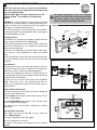
6
(1) Header bracket
(2) Chain
(3) Rail
(4) Trolley
(5) Rail bracket
(6) Hanging bracket
(7) Power cord
(8) Opener
(9) Manual release rope & handle
(10) Straight door arm
(11) Curved door arm
(12) Door bracket
(13) C-Rail brackets
(14) Centre rail bracket
As you proceed with the assembly, installation and adjustment procedures in this manual, you may find it helpful to
refer back to this illustration of a completed installation.
COMPLETED INSTALLATION
10 (4x)
9 (8x)
8 (4x)
7 (1x)
6 (1x)
1 (1x)
2 (1x)
3 (4x)
4 (4x)
5 (4x)
HARDWARE PROVIDED
(1) Clevis pin 80 mm
(2) R clip
(3) Hexagonal head screw
(4) Nut M8
(5) Flat washer M8
(6) Clevis Pin
(7) R clip
(8) Screw ST6 x 50 mm
(9) Screw ST6,3 x 18 mm
(10) Wallplug 8mm
Drill Bits
10
TOOLS REQUIRED
4
5
6

30 V DC
+ -
0 1 2 2 3 4 5 6 7
UP
DOWN
PROG
LEARN
(YELLOW)
INDICATOR
LED
1
2
3
4
5
6
7
8
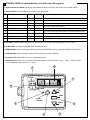
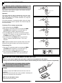
1. External Accessory Power: 30 Vdc 50 mA available for universal receiver (not active in Low standby mode).
2. Terminal Block: used for external accessories (see chart below).
3. UP Button: used for initial programming, to drive the door UP, and for displaying Diagnostic Code - Digit 1.
4. PROG Button: used to program door limits, and other features.
5. DOWN Button: used for initial programming, to drive the door DOWN, and for displaying Diagnostic Code - Digit 2.
6. LEARN Button: used to program remote controls and learn the forces manually.
7. Indicator LED: used to indicate various programming modes.
8. Green Button: used to activate the door when remote controls are not available. Open - Stop - Close via finger
access through the hole in the access cover.
No Function Colour Polarity Comment
0
E-Serial port Green +ve
Serial Communication Input
1
Push button Red +ve
Dry Contact input for push button wired wall controls
2 Ground White -ve
Common terminal for push button
2
Ground White -ve
Common terminal for IR Beams
3
IR Sensor Gray +ve Merlin IR Beam Input: (pulsing type only)
4
Door-in-door Green +ve
For Door in Door dry contact sensor: (4&5 are normally linked)
5
Door-in-door Green -ve Common terminal for Door in Door sensor
6
Flasher Black +ve Flashing light output: (24 Vdc 150 mA) while door is in motion
7
Flasher White -ve Flashing light output: negative terminal
CONTROL PANEL (located under the cover at the rear of the opener)
5
7

A
SSEMBLY SECTION
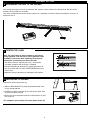
6
36 - 38 mm
1
TIGHTEN THE CHAIN
3
4
5
2
A
1
X
Remove the foam transport lock (X)
1.Slide the RAIL BRACKET (1) onto the powerhead end of the
rail (A) around 200 mm.
2.Position the rail drive spocket (2) over the opener motor shaft
(3) and push down to install.
3.Secure the rail on the opener with two C-Rail brackets (4) and
the screws (5).
This completes the assembly of the door opener to the rail.
FASTEN RAIL TO OPENER
9
10
Your garage door opener and rail are packed in two separate cartons. Remove the Power Head, Rail and all the
hardware in preparation for assembly.
T
he chain is pretensioned from the factory, however, it is advisable to check the tension and adjust if necessary as
outlined in step 9.
ASSEMBLING THE RAIL TO THE OPENER
8
Note: The spring must be able to compress and bounce
during operation. Final tensioning can be performed after
installation if necessary. Over tightening the chain may
overload the system and cause excessive wear.
1.Tension the chain by adjusting the nut (1), on the pulley
assembly, clockwise until the spring is engaged.
2.Continue tightening to compress the spring and remove all
the slack in the chain. DO NOT OVERTIGHTEN but ensure
chain is firm.
3.Adjust the spring to 36-38 mm as indicated in the diagram.

7
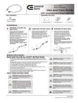
Wear protective goggles when working overhead to protect your eyes from injury.
Disengage all existing garage door locks to avoid damage to the garage door.
To avoid serious personal injury from entanglement, remove all ropes connected to the garage door before
installing the opener.
INSTALLATION SECTION
3
1
2
4
3
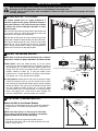
T
he header bracket must be rigidly fastened to a
structural support of the garage. Reinforce the wall or
ceiling with a 40 mm (1-1/2") board if necessary. Failure
to comply may result in improper operation of safety
reverse system.
You can attach the header bracket either to the header wall
(1) or to the ceiling (3). Follow the instructions which will
work best for your particular requirements.
With the door closed, mark the vertical centre line (2) of the
garage door. Extend line onto header wall above the door.
Open door to highest point of travel. Draw an intersecting
horizontal line (4) on header wall 50 mm for Sectional
Doors, and up to 200 mm for Tilt Doors, above high point to
provide travel clearance for top edge of door.
NOTE: Refer to vertical centre and horizontal lines created in
the previous section for proper placement of header bracket.
A. Wall mount: centre the header bracket (1) on the vertical
centre line (2) with the bottom edge of the header bracket on
the horizontal line (4) (with the arrow pointing toward the
ceiling). Drill and secure the Header Bracket using the most
suitable variation of holes (5). If using the wood screws
provided, uses a 4.5 mm pilot drill. If securing to a metal fixture,
self tapping “tek” screws may be more suitable.
B. Ceiling mount: extend vertical centre line (2) onto the ceiling.
Centre the header bracket (1) on the vertical mark no more
than 150 mm (6") from the wall. Make sure the arrow is pointing
toward the opener. Drill and secure the Header Bracket using
the most suitable variation of holes (5). If using the wood
screws provided, uses a 4.5 mm pilot drill. If securing to a metal
fixture, self tapping “tek” screws may be more suitable. For
concrete ceiling fixtures, 8 mm wall plugs are provided.
2
50 mm
3
1
4
A
150 mm
(6")
1
2
3
5
5
2
3
1
4
up to
200 mm
(50 to 200 mm depending on door type)
INSTALL THE HEADER BRACKET
HEADER BRACKET POSITIONING
1
2
Attach the Rail to the Header Bracket
• Position the assembled opener on the garage floor below the
header bracket. Use foam packing material as a protective
base.
NOTE: If the door spring is in the way youʼll need help.
Have someone hold the opener securely on a temporary
support to allow the rail to clear the spring.
• Position the rail bracket against the header bracket.
• Align the bracket holes and secure with the 80 mm clevis pin
and “R” clip (1) and (2).
ATTACH RAIL TO HEADER BRACKET
11
12
13

8
Rail
Door
50 mm spacer should
be used to determine
the correct mounting
position
Header
Bracket
50 mm (2”)
above the highest
point of travel
POSITION THE OPENER
SECTIONAL DOOR
You will need a 50 mm piece of timber or similar spacer to gauge the distance between door and rail.
1.Raise the opener onto support.
2.Open the door completely, place a 50 mm spacer between the door and the rail (as shown).
3.The final positioning of the rail should be relatively parallel to the horizontal door panels.
14
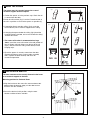
Disengage the trolley mechanism (see section “Operating the manual release”) and slide it back towards the powerhead.
S
ecure the hanging push arm up into the rail assembly temporarily using tape or rope, to avoid a hazard.

9
X
A
fig.1
fig.2
fig.3
fig.4
HANG THE OPENER
100-300 mm
A
The door bracket must be securely fastened to the frame
or a structural support on the door.
Mounting position for Sectional Doors
1.Align the bracket on the centre line, measure down 100-
300 mm from the door top edge (use the door bracket
that best suits the situation).
2.Secure the bracket in this position, using the most
suitable variation of holes available.
FASTEN DOOR BRACKET
15
16
The opener must be securely fastened to a sound
structural support above the opener.
1
.Postion the opener as in the previous step. Check the rail
is centred over the door.
E
nsure the rail brackets (fig.1) is on the Powerhead end of
the rail in a position as close to the opener as possible (X).
2.If mounting directly onto the ceiling, (fig.2) screw the
bracket directly into a structural support on the ceiling.
3.If hanging the opener below the ceiling, (fig.3) bend the
hanging brackets provided, and secure to both the ceiling
and the rail bracket.
4.The centre rail bracket is recommended on large
doors. Install the centre rail bracket in the mid position of
the rail. Simply slip both halves over the top of the rail
(fig.4), and secure to the ceiling, either directly or with
hanging strips.
5.Check the opener is securely centred over the door.
Remove the 50 mm spacer, and any other assembly
tools. Operate the door manually and check for
unrestricted operation.

10
Connect Electric Power
TO AVOID INSTALLATION DIFFICULTIES, DO NOT RUN THE GARAGE DOOR OPENER UNTIL INSTRUCTED TO DO SO.
Connect to properly fused and earthed power outlet.
- Ensure all ropes and installation tools have been removed from the door.
- When the opener is switched ON, the operator light flashes a number of times and then remains ON.
1
2
Instruction
label
Instruction
label
1
2
3
Trolley Screws
Fig. 1
Fig. 3
4
5
Fig. 2
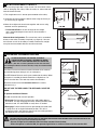
Make sure the garage door is fully closed. Pull the manual release
cord to disengage the trolley. Slide the trolley to around 300 mm
from the header bracket.
1.The straight door arm is already preassembled to the trolley.
2.Install the curved arm onto the door bracket using the Clevis pin
(2) and R-Clip (3) supplied.
3.Move the straight and curved arms together and secure using
two bolts and nuts provided (4).
- For Sectional Doors: ensure the angle of the straight
arm is around 20 degrees from vertical, when the door is
fully closed.
Alternate Arm Configuration: The curved arm can be assembled
directly to the trolley assembly if required (see figure 3). Unscrew
the front two screws in the trolley assembly. Remove the straight
arm pivot and reassemble with the curved arm bracket.
ATTACH DOOR ARM TO TROLLEY
OPERATING THE MANUAL RELEASE
The manual release mechanism enables the door to be manually
operated during power outages or in an emergency.
The RED Manual Release cord is preassembled to the trolley. When
the opener is installed the handle should be no higher then 1.8
metres from the floor. The cord may need to be extended.
Attach the manual release Instruction Label to the cord as
indicated in fig 1.
DO NOT USE THE RED HANDLE TO OPEN AND CLOSE THE
DOOR.
To operate the Manual Release:
The door should be fully closed if possible.
1.Disengage: Pull the manual release rope and handle down to
disconnect. This will disengage the trolley, allowing the door to be
moved by hand, UP and DOWN as many times as needed.
2.Re-engage: Pull the manual release rope towards the motor until
it springs back to its original horizontal position. This will re-
engage the trolley, and when the door passes the trolley position it
will automatically re-engage the opener.
DO NOT DISENGAGE THE OPENER TO MANUAL
OPERATION WITH CHILDREN , PERSONS OR OTHER
OBJECTS INCLUDING MOTOR VEHICLES WITHIN THE
DOORWAY : (The door is under significant tension and if the door
has developed a fault or incorrect tension, it may be unsafe and may
fall rapidly.)
17
18

11
Without a properly installed safety reversal
s
ystem, persons (particularly small
children) could be SERIOUSLY INJURED or
KILLED by a closing door.
• Incorrect adjustment of garage door travel limits
will interfere with proper operation of safety
reversal system.
•
NEVER use force adjustments to compensate for a
binding or sticking garage door.
• After ANY adjustments are made, the safety
reversal system MUST be tested. Door MUST
reverse on contact with 40 mm high object laid flat
on floor.
To prevent damage to vehicles, be sure fully open
door provides adequate clearance.
Indicator LED
Indicator LED
figure 2
figure 3
Indicator LED
figure 4
Indicator LED
figure 5
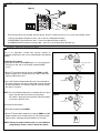
Travel limits regulate the points at which the door will stop
when moving UP or DOWN. The travel limit buttons are located
under the access cover on the rear panel (figure 1).
NOTE: This opener uses a POSITION TAB attached to the chain
which activates a mechanical passpoint during the door travel.
The indicator LED will blink when this occurs. If the passpoint
is not activated during the door travel process, the travel limits
cannot be programmed.
TO PROGRAM THE TRAVEL LIMITS:
1. Press the PROG Button until the UP Arrow Button and indicator
LED begin to flash (figure 2).
2. Press and hold the UP Arrow Button until the door is in the
desired UP position (figure 3).
NOTE: The UP and DOWN Arrow Buttons can be used to move
the door up and down as needed.
3. Once the door is in the desired UP position press and release the
PROG Button. The DOWN Arrow Button will begin to flash (figure
4).
4. Press and hold the DOWN Arrow Button until the door is in the
desired DOWN position (figure 5).
NOTE: The UP and DOWN Arrow Buttons can be used to move
the door up and down as needed.
5. Once the door is in the desired DOWN position press and release
the PROG Button. The UP Arrow Button will begin to flash (figure
2).
SETTING THE FORCE (AUTO):
6. Press and release the UP Arrow Button to test the UP limit. When
the door has travelled to the programmed UP limit, the DOWN
Arrow Button will begin to flash.
7. Press and release the DOWN Arrow Button to test the DOWN
limit. The door will travel to the programmed DOWN limit.
The indicator LED will stop flashing. The travel limits and force
setting has now been set. Proceed to test safety reverse system.
SETTING THE FORCE (MANUAL LEARN IF REQUIRED):
1. Open the rear access panel. Locate the yellow Learn button.
2. Push the yellow Learn button twice to enter unit into force
adjustment mode. The LED (indicator light) will flash quickly.
3. Push the programmed remote control or push the UP/DOWN
arrow at the programming display bar. The door will travel to the
DOWN (close) position. Push the remote control again, the door
will travel to the UP (open) position.
4. Press and release the DOWN Arrow Button to test the DOWN
limit. The door will travel to the programmed DOWN limit.
The LED (indicator light) will stop flashing when the force has
been set. The door must travel through a complete cycle, UP
and DOWN, in order for the force to be set properly. If the unit
cannot open and close your door fully, inspect your door to insure
that it is not sticking or binding.
The Force Setting has now been set manually.
PROGRAM THE TRAVEL LIMITS AND FORCE SETTINGS
figure 1
A
DJUSTMENT SECTION
19
“The Protector System
TM
” must be used for
all installations where the closing force as
measured on the bottom of the door is over
400 N (40 kgf).
Installers should ensure that the doors are installed
in a compliant manner as per AS/NZS 60335-2-95.

12
DOOR SPEED SELECTION:
The “CyclonePro” opener has been designed to work with a wide range of garage doors with a total mass up to 286kg.
The CyclonePro can be set on NORMAL speed when operating doors with a total mass of less than 130Kg.
“The Protector System
TM
”must be used for all installations where the closing force as measured on the bottom of the
door is over 400 N (40 kgf).
When the CyclonePro is installed on doors with a total mass exceeding 130kg the operator should be set on SLOW
speed mode. The “Protector System” must be installed when SLOW speed mode is selected.
Installers should ensure that the doors are installed in a compliant manner as per AS/NZS 60335-2-95.
TRAVEL SPEED:
There are two travel speeds available for this opener.
Factory default is set to the NORMAL speed.
TRAVEL SPEED: Manually selected:
The speed can be set manually if required, using the following method.
To activate the alternate speed:
PRESS and HOLD both the UP and DOWN arrows for 3 seconds.The courtesy lamp will flash once to confirm SLOW
speed and twice to confirm NORMAL speed.
To deactivate the selected speed: Repeat the process above (toggle between the two settings).
PROGRAM THE TRAVEL SPEED
21
TEST THE SAFETY REVERSE SYSTEM
P
rocedure: With door opened place a 40 mm obstacle (1) laid flat on the floor
under the garage door. Operate the door in the down direction. The door must
reverse off the obstacle. If the door stops on the obstacle, remove obstacle and
repeat Program the Limits and Force Steps, then repeat safety reverse test.
When the door reverses off the 40 mm obstacle, remove the obstacle and run the
opener through a complete travel cycle. Door must not reverse in closed position. If
it does, repeat Program the Limits and Force then repeat safety reverse test.
1
40 mm high
The safety reverse system test is important. Garage door must reverse on contact with a 40 mm obstacle
l
aid flat on the floor. Failure to properly adjust opener may result in serious personal injury from a closing
garage door. Repeat test once a month and adjust as needed.
20
Low Standby Mode (sub 1 watt) is activated by the factory to deliver the lowest possible standby power.
In this mode the External Accessories Power and the IR Beams are turned OFF when the door is closed and the courtesy light
is OFF. IR Beams operate normally in Low Standby mode.
At mains turn ON: Courtesy light flashes 2 times = Low Standby Mode
Courtesy light flashes 10 times = Normal Standby Mode
The Normal Standby Mode will need to be activated for External Accessories Power.
To Activate Normal Standby Mode:
Turn the mains power OFF.
PRESS and HOLD both the UP and DOWN arrows simultaneously.
Turn ON mains power while both the arrow buttons are still pressed.
Courtesy light comes on and after 5 seconds another 10 flashes.
Release the arrow buttons.
To Activate Low Standby Mode:
Turn the mains power OFF.
PRESS and HOLD both the UP and DOWN arrows simultaneously.
Turn ON mains power while both the arrow buttons are still pressed.
Courtesy light comes on and after 5 seconds another 1 flash.
Release the arrow buttons.
PROGRAM THE LOW STANDBY MODE (OPTIONAL)
22
Indicator LED
g.
n
e

NOTE: This accessory must be used for all installations
where the closing force as measured on the bottom of the
d
oor is over 400 N (40 kgf).
S
PECIAL NOTE: Merlin strongly recommends that The
Protector System
TM
be installed on all garage door
openers.
I
R BEAMS: By installing IR Beams, an open door is prevented
from closing if a person or object is located in the beam area. If
the door is already closing, it will return to the open position. A
closed door is not prevented from opening.
If the Protector System
TM
is installed and needs to be removed,
the opener will need to be reprogrammed (refer to paragraph 4
of the troubleshooting section).
Assembly Process:
The IR Beams are supplied preassembled, complete with two
sensors, wiring and wall brackets. (fig1 & fig2)
Install the mounting brackets and sensors to either side of the
inside of the garage door, and at a height of no greater than
100 mm off the garage floor.
The brackets are designed to be used for Wall or Floor fixing,
with a variety of hole combinations to achieve the desired
results.
Drill the required holes and install the brackets with wall plugs
and screws provided. Ensure they do not obstruct the door
movement.
Wiring Process:
Align the Sensors to face each other and tighten if necessary.
The wiring should exit from the bottom of the housing to
maintain the correct IP rating and continued operation.
One sensor is a Sending Eye , the other is a Receiving Eye. Try
to avoid positioning these in direct sunlight as this may interfere
with the operation of the beams.
Run both sets of wire back to the power head CONTROL
PANEL. Ensure the wire is well supported and does not
interfere or get damaged by movement of the door panels or
spring hardware.
Remove Power from the Unit:
At the Power head end, cut the wires to the correct length and
strip each back around 10 mm.
Twist both White wires together and install into “quick release”
terminal 2 (white) (fig 3)
Twist both Black/White wires together and install into “quick
release” Terminal 3 (Grey) (fig 3)
(The sensors are a 2 wired system connected in a parallel
configuration).
Reinstall Power to the Unit:
When aligned correctly the Red LED on each sensor will
remain “ON constantly”.
If incorrectly aligned both LEDs will “flash”.
Correct the alignment if necessary.
The opener is now ready to be checked for correct IR Beam
operation.
30 V DC
+ -
0 1 2 2 3 4 5 6 7
UP
DOWN
PROG
LEARN
(YELLOW)
INDICATOR
LED
Black/White x 2White x 2
PLASTIC WALL
PLUG
LLAW
W
ERCS
WALL
B
RACKET
EGNALFM6
T
UN
HCAOCM6
WERCS
RI747
M
AEB
2 CORE
WIRE CABLE
figure 1
figure 2
figure 3
13
INSTALL THE PROTECTOR SYSTEM
TM
(see section 21 if required)
T
o prevent entrapment, install The Protector
System™ no higher than 100 mm above the floor.
Disconnect power to the garage door opener
before installing The Protector System™.
23
view 1
view 2

TIMER TO CLOSE FEATURE (TTC)
The Timer to Close feature requires The Protector System
TM
(IR Beams) to be installed.
Operation:
This feature allows the door to automatically close from a fully
open position after a specified time. The delay can be set from
10 to 180 seconds in 10 second increments, by using the
opener control buttons.
If the door encounters an obstruction while closing, the door
will stop and return to the UP position. The Courtesy lamp will
then flash 10 times.
To Activate TTC, or change a preset time:
1.Start with the door fully CLOSED.
2.Enter into TTC Activation mode by pressing both PROG
and DOWN buttons together for 3 seconds (figure 2).
Release when the courtesy light flashes twice.
3.Press the UP button once for each 10 second increment
required of TTC (figure 3. eg. twice for 20 seconds). Press
the DOWN arrow to reduce, if needed.
4.Press and release the PROG button to save this time
(figure 4), Courtesy light will flash once. TTC is now
activated.
TEST: Operate the door to the UP position. Keep clear of the
IR Beams and check the door closes after the preset time.
To Deactivate TTC:
1.Enter into TTC Activation mode by pressing both PROG
and DOWN buttons together for 3 seconds (figure 2).
Release when the courtesy light flashes twice.
2.Press and release the PROG button to save (figure 4),
courtesy light will flash once. TTC is now deactivated.
Indicator LED
Indicator LED
Door Fully Closed
figure 1
Indicator LED
figure 4
or
figure 5
Door may operate unexpectedly, therefore do not
allow anything to stay in the path of the door.
INSTALLING YOUR E138M WIRELESS WALL BUTTON
To install:
• Carefully pry open the E138M and locate the two screws for
mounting.
• Attach to the wall using the two screws provided. If mounting to a
plaster wall, wall plugs may be required.
NOTE: Do not overtighten screws.
• Replace the front cover plate.
+
Disconnect power to the opener before installing
this accessory to prevent accidental activation.
Locate minimum 1.5 m above the floor.
NOTE: The wall control supplied with your opener should be pre-programmed by the factory.
If adding a new wall control, program into the opener before mounting the unit as detailed in Wireless Programming.
14
25
24
Indicator LED
figure 2
figure 3

This is an adjustable, second stop position suitable for
ventilation, pedestrian or pet access, programmed to the Remote
Control.
To Activate this feature:
1.Start with the door fully CLOSED (figure 1). Drive the opener
UP (figure 2) and stop at the position required for PET
access.
2.Enter PET activation mode by pressing the PROG and UP
buttons together for 3 seconds (figure 3). Release when the
Courtesy light flashes once.
3.Press the Remote Control button that you have allocated for
this feature (figure 4). Do not use the button already allocated
for normal operation. The Courtesy light will flash once when
the code is accepted.
TEST: Press the Remote Control once, and door will close, press
again, and door will return to the preset position.
If the door is above the preset position, when the button
is pressed, it will fully close.
To Deactivate this feature:
1.Start with the door fully CLOSED.
2.Enter PET deactivation mode by pressing the PROG and UP
buttons together for 3 seconds (figure 3). The Courtesy light
will flash twice, indicating the deactivation has occurred.
NOTE: Erasing all remote control codes, as in the Wireless
programming section, will also delete this feature.
PARTIAL OPENING FEATURE (PET)
15
Indicator LED
Indicator LED
Door Fully Closed
figure 1
figure 3
or
27
1
service
www
m
@ m
B
B
A
2
114A3361
ForServiceCall
I
nstallationDate
3
132A2900
RISK OF ENTRAPMENT
Repeat Safety Reverse Test monthly. Door
must reverse on contact with a 40mm obstacle
placed on the floor. Make necessary adjustments.
AUTOMATIC DRIVE:
Keep away from the area of the door since it may
operate unexpectedly.
EMERGENCY RELEASE:
To release, pull down firmly on the red handle.
114A3361
F
or Service Call
Installation Date
l
l
26
INSTALL WARNING LABELS
Three warning labels are provided with this opener: attach as indicated in the fig 1 to a clean and suitable surface.
1. Risk of entrapment: (English version) - place close to a fixed Wall Control(1).
2. EMERGENCY Release/Service label: - place on the Manual Release cord (2).
3. WARNING Child Entrapment: (triangle label) - place on a low inside panel of the door (3).
figure 4
figure 1
Indicator LED
figure 2

16
NOTE: The transmitter(s) and wireless wall button supplied with
y
our opener are preprogrammed by the factory.
If you purchase additional transmitters, the garage door opener must
be programmed to accept the new remote code.
Program the Receiver to Match Additional Transmitter Codes:
Using the yellow “LEARN” Button
1.Press and Hold the button on the hand-held remote or wall button that
you wish to use (1).
2.Press and release the yellow “LEARN” buton on the opener (2).
3.Release the remote button when the opener light flashes. It has learnt
the code. If you release the remote control push button before the
opener light flashes, the opener has not learnt the code.
Now the opener will operate when the remote control push button is
pressed.
To Erase all Remote Control Codes
1.Press and Hold the yellow “LEARN” button on the opener until the
indicator LED goes ON, and continue holding for approx. 6 seconds,
until the indicator LED goes out.
1.Release the button, all codes are now erased.
Wireless Keypad E840M
To set the keyless entry PIN:
1.Locate the yellow “LEARN” button on the garage door opener.
2.Press and release the yellow “LEARN” button. The LED indicator
light will glow steadily.
3.Enter a 4-digit personal identification number (PIN) of your choice
on the keypad.
4.Press and hold the ENTER button. Check to see if the opener light
flashes. Release the ENTER button after the light flashes.
To change an existing keyless entry PIN:
1.Enter the existing programmed PIN that you want to change.
2.Press and hold the # button until the courtesy light flashes twice.
3.Enter the new 4-digit PIN of your choice, then press the ENTER
button. The light will flash once.
4.To test, enter the new PIN, then press the ENTER button. The
garage door opener will activate.
Activate the opener only when door is in full view, free of obstruction and properly adjusted. No one should
enter or leave garage while door is in motion. Do not allow children to operate push button(s) or remote(s).
Do not allow children to play near the door.
Yellow “Learn” Button
1
2
2
3
4
3
Press and release
the yellow
learn button
Enter a 4-digit
PIN of your
choice
? ? ? ?
_ _ _ _
Press and hold
the enter button
Opener light flashes
After the lights
flash release the
ENTER button
1
Locate
the yellow
learn button
28
WIRELESS PROGRAMMING (OPTIONAL ACCESSORIES)

USING YOUR OPENER
1. Your opener can be activated by any of the following devices:
• Opener control panel: Up and Down Buttons and Green O.S.C.
• The Outside Keyswitch or Keyless Entry System (if you have
installed either of these accessories).
• The Remote Control Transmitter. Hold the push button down until
the door starts to move.
2. Opening the Door Manually: Door should be fully closed if
possible. Weak or broken springs could allow an open door to
fall rapidly. Property damage or serious personal injury could
result.
NOTE: For full instructions on how to operate the door manually
refer to section 18.
The door can be opened manually by pulling the release handle
down. To reconnect the door, pull the manual release rope towards
the motor until it springs back to its original horizontal position.
Do not use the manual release handle to pull the door open
or closed.
3. When the Opener is Activated by Remote Control:
1. If open, the door will close. If closed, the door will open.
2. If closing, the door will stop.
3. If opening, the door will stop (allowing space for entry and exit of
pets and for fresh air).
4. If the door has been stopped in a partially open or closed position,
it will reverse direction.
5. If an obstruction is encountered while closing, the door will reverse
to the UP limit.
6. If an obstruction is encountered while opening, the door will
reverse and stop.
7. The optional Protector System™ uses an invisible beam which,
when broken by an obstruction, causes a closing door to open
and prevents an open door from closing. It is STRONGLY
RECOMMENDED for homeowners with young children.
4. The opener lights will turn on under the following conditions:
when the opener is initially plugged in; when power is restored after
interruption or when the opener is activated.
Lights will turn off automatically after 2-1/2 minutes.
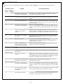
Once a Month
• Manually operate door. If it is unbalanced or binding, call a
qualified door technician.
• Check to be sure door opens & closes fully. Adjust limits
and/or force if necessary.
• Repeat the safety reverse test. Make any necessary
adjustments.
Once a Year
• Lightly grease the chain and inside the rail assembly where
the trolley slides.
• Internally the opener does not require additional lubrication.
• Lightly grease the chain and inside the rail assembly where
the trolley slides. Be careful to use gloves around any sharp
metal edge or the rail.
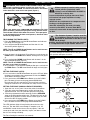
Battery of the remote control:
T
he batteries in the remote have an extremely long life.
If the transmission range decreases, the batteries must be
replaced. Batteries are not covered by the warranty.
Replacing battery (CR2032):
To replace battery, turn remote control around and open the
case with a screwdriver. Lift cover and lift control board below.
Slide battery to one side and remove. Observe polarity of
battery!
Assemble again in reverse direction.
REPLACE BATTERIES IN REMOTES
1
2
V
D
C
Pb Cd Hg
CARE OF YOUR OPENER
To prevent SERIOUS INJURY OR DEATH:
o
bserve the following instructions for the
battery
- NEVER allow small children near batteries.
- If battery is swallowed, immediately notify doctor.
- Danger of explosion if battery is replaced improperly.
- Replacement only by identical or equivalent type.
- Dispose of old battery properly. Batteries should not
be treated as household waste. All consumers are
required by law to dispose of batteries properly at the
designated collection points.
- Never recharge batteries that are not meant to be
recharged.
- Do not short-circuit batteries or take them apart.
- If necessary, clean contacts on batteries and contacts
before loading.
- Never expose batteries to excessive heat such as
sunshine, fire or the like!
17
29
31
30
or
Carefully
Remove Battery
(CR2032 x 1)
MAINTENANCE AND CARE OF YOUR OPENER
To replace battery for optional remote control transmitters -
E950M,E943M, E940M & E945M, use a screwdriver blade to
pry open the case as shown. Insert battery positive side up.

004C5502
Door bracket
178A0103
Straight arm
012C0778
Hanging brackets
083A0011
Grease
004C5600
Hardware bag
012C0788-1
Header bracket
Replacement chain packs
041A4045-2 (2.4m)
0
4
1
A
4
0
2
0
S
p
r
o
c
k
e
t
a
s
s
e
m
b
l
y
041A0043
Trolley latch (chain)
041A4017-1
Motor shaft adapter (metal)
041A4038
Pulley assembly
012A1028
Rail bracket
041A4039
C-Rail bracket
One piece rail asssembly
7024CR5 2.4 m
002A1850
Trolley with rope &
straight arm
041A4016
Position tab (chain)
178A0104
Curved arm
041A4036
Centre Rail bracket
012A1027
Door bracket
REPLACEMENT PARTS
33
18
ACCESSORIES
7
6
8
5
E840M
760E
E1702M
774ANZ
E940M E943M
E945M
9
10
3
4
E950M
E138M
1
2
E960M
32
NOTE: Use of any Chamberlain Group accessories are approved to use with this opener. This includes genuine Merlin accessories.
Generic compatible accessories are NOT approved for use with this opener.
(1) Model E138M Wireless wall button
(2) Model E960M 4 Channel remote control
(3) Model E950M 4 Channel remote control
(4) Model E940M 1 Channel visor remote control
(5) Model E943M 3 Channel visor remote control
(6) Model E945M 3 Channel mini remote control
(7) Model E840M Keyless entry system
(8) Model 774ANZ The Protector System
TM
(9) Model E1702M Quick release lock
(10) Model 760E Outside keyswitch

19
REPLACEMENT PARTS
I
f the supply cord is damaged, it must be
replaced by the manufacturer, its service
agent or similarly qualified persons
in order to avoid hazard.
P
ower Cord
026B0181
0
41A4004
Passpoint
Assembly
041A4027
Transformer
0
41A1847
Logic Board / PCB Housing / Control Cover (assembly)
041A4002-1
LED Module
041A1805
Lens Cover
041A0227
Motor Assembly
041A4023-1
Power Board
041A1804
Brand Cover
041A0744
Chassis Cover
RAIL REPLACEMENT PARTS
041A4017-1
Motor shaft adapter (metal)
041A0043
Trolley latch (chain)
041A4016
Position tab (chain)
34
Page is loading ...
Page is loading ...
Page is loading ...
Page is loading ...
-
 1
1
-
 2
2
-
 3
3
-
 4
4
-
 5
5
-
 6
6
-
 7
7
-
 8
8
-
 9
9
-
 10
10
-
 11
11
-
 12
12
-
 13
13
-
 14
14
-
 15
15
-
 16
16
-
 17
17
-
 18
18
-
 19
19
-
 20
20
-
 21
21
-
 22
22
-
 23
23
-
 24
24


Merlin PowerAce MT60EVO Installation And Operating Instructions Manual
- Category
- Garage Door Opener
- Type
- Installation And Operating Instructions Manual
- This manual is also suitable for
Ask a question and I''ll find the answer in the document
Finding information in a document is now easier with AI
Related papers
-
Merlin Entrylift MT50EVO Installation And Operating Instructions Manual
-
-
-
-
-
-
Merlin Merlin Whisper Drive MT3850EVO Installation And Operating Instructions Manual
-
-
-
Other documents
-
Other BERGEN EXTRA HANGING RAIL User manual
-
SkyLink TR-010 User manual
-
 Commercial Electric 0018-0003 User guide
-
Chamberlain PowerLift Plus CS100EVO Installation And Operating Instructions Manual
-
Chamberlain MOTORLIFT 5500 User manual
-
Genie PMX-60 Remote Instruction
-
Chicago Electric 95593 - 1.5 HP Operating instructions
-
Chamberlain LiftMaster LM650EVGB Owner's manual
-
Craftsman 13953978SRT User manual
-
