Page is loading ...

User’s Guide
omega.com
e-mail: [email protected]
iSeries info:
omega.com/specs/iseries
For latest product manuals
omegamanual.info
®
®
Shop on line at
Embedded Ethernet for iSeries
Monitor/Controller
-C4EIT/-EIT
RoHS 2 Compliant


TABLE OF CONTENTS
Part 1: Introduction ................................................................................................2
1.1 Safety and EMC Considerations...........................................................2
1.2 Description .............................................................................................3
Part 2: Hardware ................................................................................................4
2.1 Physical Characteristics and Mounting ...............................................4
2.2 Rear Panel of iSeries Meter with Embedded Ethernet Server ...........5
2.3 Serial Communication Interfaces (For Models with RS485 Port) ......5
2.3.1 Wiring RS485 Interface...........................................................6
2.4 Network Communication Interfaces.....................................................7
2.4.1 10BASE-T RJ-45 Pinout .........................................................7
2.4.2 Connecting iServer to PC/Hub/Switch/Router .....................7
Part 3: Network Configuration..................................................................................8
3.1 Network Protocols ...........................................................................8
3.2 Ethernet (MAC) Address .................................................................8
3.3 DHCP ...............................................................................................9
3.4 DNS ...............................................................................................9
3.5 IP Address ........................................................................................9
3.6 TCP Port (Socket) Number.............................................................10
Part 4: Operations ..............................................................................................11
4.1 Serial Interface Configuration-Communication Protocol .................11
4.2 Command Structure.............................................................................11
4.3 Command Formats...............................................................................11
4.4 Default IP Address ...............................................................................13
4.5 Access and Configuration Using a Web Browser.............................14
4.5.1 Overview................................................................................15
4.5.2 Network..................................................................................16
4.5.3 Serial (RS485 Serial Port).....................................................18
4.5.3.1 RS485 Serial Port............................................................18
4.5.3.2 Network-to-Serial ............................................................19
4.5.3.3 Packing Techniques .......................................................20
4.5.3.4 Multi-Host Connection ...................................................21
4.5.4 Configuration ........................................................................22
4.5.4.1 Date and Time .................................................................23
4.5.5 Management
..........................................................................24
4.5.5.1 Management - Email SNMP............................................25
4.5.5.2 Management - Alarm.......................................................26
4.5.5.2.1 Sending Txt Messages to a Cell Phone .....................27
4.5.6 Security..................................................................................28
4.5.7 Device Query.........................................................................29
4.5.8 Device Setup .........................................................................30
4.5.8.1 Device Parameters -C4EIT .............................................31
4.5.8.2 Device Setup -EIT ...........................................................32
i

4.5.8.3 Device Parameters -EIT..................................................33
4.5.9 Readings................................................................................34
4.5.9.1 Readings - Device Setpoints .........................................34
4.5.10 Terminal ................................................................................35
4.5.11 System .................................................................................36
4.5.12 Diagnostics .........................................................................37
4.5.12.1 Diagnostics - Serial Port ..............................................37
4.5.12.2 Diagnostics - Ethernet Port .........................................38
4.5.12.3 Diagnostics - Ping ........................................................38
Part 5: Specifications ............................................................................................ 39
Part 6: Factory Preset Values ................................................................................41
Part 7: Approvals Information ...............................................................................42
Appendix A Glossary ..........................................................................................43
Appendix B IP Address ......................................................................................44
Appendix C IP Netmask ......................................................................................45
Appendix D ASCII Chart .....................................................................................46
ASCII Chart Control Codes ...........................................................47
Appendix E iConnect Software ..........................................................................48
Appendix F HTTPget Program ...........................................................................50
Appendix G ARP Program...................................................................................52
Appendix H Telnet Setup.....................................................................................53
Appendix I Remote Access (Tunneling)...........................................................56
Appendix J iPORT .............................................................................................61
Appendix K iLog Software ..................................................................................65
LIST OF FIGURES:
Figure 1.1 Accessing Devices Over the Ethernet ............................................3
Figure 2.1 Rear Panel View of i16, i8 and iDR Series Meters with
Embedded Ethernet Server .............................................................4
Figure 2.2 Multi-point, Half-Duplex RS485 Wiring ..........................................6
Figure 2.3 RJ-45 Pinout......................................................................................7
Figure 3.1 i8 Labeling ........................................................................................8
Figure 3.2 iDR Labeling .....................................................................................8
ii

Figure 3.3 i16 Labeling ......................................................................................8
Figure 4.1 Pinging the iServer from a DOS Prompt.......................................13
Figure 4.2 iServer LOGIN Page........................................................................14
Figure 4.3 iServer LOGIN and ADMINISTRATOR Passwords .......................14
Figure 4.4a iServer -C4EIT OVERVIEW Page ...................................................15
Figure 4.4b iServer -EIT OVERVIEW Page........................................................15
Figure 4.5 iServer NETWORK Page ................................................................16
Figure 4.6 iServer SERIAL Page – RS485 Serial Port....................................18
Figure 4.7 iServer SERIAL Page – Network to Serial ....................................19
Figure 4.8 iServer SERIAL Page – Packing Techniques ...............................20
Figure 4.9 iServer SERIAL Page – Multi-Host Connection............................21
Figure 4.10 iServer CONFIGURATION Page – Ethernet Configuration..........22
Figure 4.11 iServer MANAGEMENT Page – Email, SNMP...............................24
Figure 4.12 iServer MANAGEMENT Page – Alarm...........................................26
Figure 4.13 iServer SECURITY Page.................................................................28
Figure 4.14 iServer DEVICE QUERY Page ........................................................29
Figure 4.15 iServer DEVICE SETUP Page – RS485 (-C4EIT)...........................30
Figure 4.16 iServer DEVICE PARAMETERS Page (-C4EIT ..............................31
Figure 4.17 iServer DEVICE SETUP Page (-EIT) ..............................................32
Figure 4.18 iServer DEVICE PARAMETERS Page (-EIT)..................................33
Figure 4.19 iServer READINGS Page (-C4EIT) .................................................34
Figure 4.20 iServer DEVICE SETPOINTS Page ................................................34
Figure 4.21 iServer TERMINAL Page.................................................................35
Figure 4.22 iServer SYSTEM Page ....................................................................36
Figure 4.23 iServer DIAGNOSTICS Page ..........................................................37
Figure E-1 Assigning an IP Address using iConnect ....................................48
Figure E-2 Accessing the iServer’s HOME Page ...........................................49
Figure F-1 ARP Commands and Responses .................................................51
Figure G-1 ARP Commands and Responses .................................................52
Figure H-1 Tera Term Telnet Connection Screen ...........................................53
Figure H-2 Telnet Setup - iServer Configuration Page ..................................53
Figure H-3 Telnet Setup - iServer Help Page ..................................................54
Figure I-1a Serial Tunneling ..............................................................................56
Figure I-1b Serial Tunneling - Embedded PCB iServer...................................
56
Figure I-2 Device-to-Device Communication.................................................57
Figure 1-3 SERIAL - Multi-Host Connection (-C4EIT) ....................................59
Figure J-1 Direct Serial Connection ................................................................61
Figure J-2a Redirect Serial Connection............................................................62
Figure J-2b Redirect Serial Connection - Embedded PCB iServer ................62
Figure J-3 iPORT Main Window.......................................................................63
Figure J-4 COM Port Window ..........................................................................63
Figure K-1 iLog Software Logging Data for an iSeries .................................65
iii

LIST OF TABLES:
Table 2.1 Rear Panel Annunciators.................................................................5
Table 2.2 Data Transmission Characteristics RS485 ....................................5
Table 2.3 Half Duplex Hookup .........................................................................6
Table 4.1 Command Prefix Letters ................................................................11
Table 4.2 Command Formats.........................................................................11
Table K-1 iLog Excel Applications .................................................................66
Table K-2 iLog Error Messages......................................................................67
iv
NOTES, WARNINGS and CAUTIONS
Information that is especially important to note is identified by following labels:
• NOTE
• WARNING or CAUTION
• IMPORTANT
• TIP
NOTE: Provides you with information that is important to successfully
setup and use the iServer.
CAUTION or WARNING: Tells you about the risk of electrical shock.
CAUTION, WARNING or IMPORTANT: Tells you of circumstances or
practices that can affect the instrument’s functionality and must refer to
accompanying documents.
TIP: Provides you helpful hints.
Before You Begin
Inspecting Your Shipment: Remove the packing slip and verify that you have
received everything listed. Inspect the container and equipment for signs of damage
as soon as you receive the shipment. Note any evidence of rough handling in transit.
Immediately report any damage to the shipping agent. The carrier will not honor
damage claims unless all shipping material is saved for inspection. After examining
and removing the contents, save the packing material and carton in the event
reshipment is necessary.
Customer Service: If you need assistance, please contact the Customer Service
Department nearest you.
Manuals, Software: The latest Operation Manual as well as free configuration
software (iConnect), and datalogging software (iLog) are available at the website
listed on the cover page of this manual.
1

PART 1
INTRODUCTION
1.1 Safety and EMC Considerations
This device is marked with the international caution symbol. It is
important to read this manual before installing or commissioning this
device as it contains important information relating to Safety and EMC
(Electromagnetic Compatibility).
This instrument is a panel mount device protected in accordance with EN
61010-1:2001, electrical safety requirements for electrical equipment for
measurement, control and laboratory. Installation of this instrument should
be done by qualified personnel. In order to ensure safe operation, the
following instructions should be followed.
This instrument has no power-on switch. An external switch or circuit-breaker
shall be included in the building installation as a disconnecting device. It
shall be marked to indicate this function, and it shall be in close proximity to
the equipment within easy reach of the operator. The switch or circuit-
breaker shall meet the relevant requirements of IEC 947–1 and IEC 947-3
(International Electrotechnical Commission). The switch shall not be
incorporated in the main supply cord.
Furthermore, to provide protection against excessive energy being drawn
from the main supply in case of a fault in the equipment, an overcurrent
protection device shall be installed.
• Do not exceed voltage rating on the label located on the top of the
instrument housing.
• Always disconnect power before changing signal and power
connections.
• Do not use this instrument on a work bench without its case for safety
reasons.
• Do not operate this instrument in flammable or explosive atmospheres.
• Do not expose this instrument to rain or moisture.
• Unit mounting should allow for adequate ventilation to ensure instrument
does not exceed operating temperature rating.
• Use electrical wires with adequate size to handle mechanical strain and
power requirements. Install without exposing bare wire outside the
connector to minimize electrical shock hazards.
EMC Considerations
• Whenever EMC is an issue, always use shielded cables.
• Never run signal and power wires in the same conduit.
• Use signal wire connections with twisted-pair cables.
• Install Ferrite Bead(s) on signal wires close to the instrument if EMC
problems persist.
Failure to follow all instructions and warnings may result in injury!
2
1.2 Description
The iServer is an Ethernet Server designed to connect devices with serial interfaces
to the Ethernet network using the TCP/IP protocol. It contains Ethernet and RS232
or RS485 interfaces.
The standard features include:
• Use standard Web Browser, TCP connection, HTTPget DOS program or Telnet
Simulation, for network connectivity.
• Install via RS232/RS485 serial port connection.
•
Transfer data from RS232/RS485 serial interface to TCP/IP using built-in socket
server.
• Use a standard home page for OEM applications.
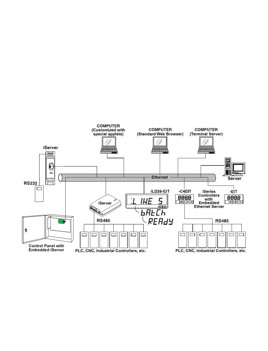
The following example illustrates how you can hookup the devices with serial
interface on the network using the iServer:
Figure 1.1 Accessing Devices Over the Ethernet
3
PART 2
HARDWARE
2.1 Physical Characteristics and Mounting
For physical dimensions and installation instructions see Quickstart and Manual for
iSeries monitor/controller.
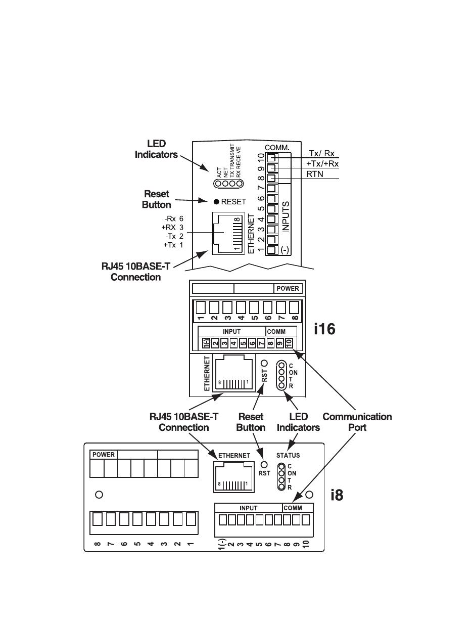
2.2 Rear Panel of iSeries Meter with Embedded Ethernet Server
Figure 2.1 Rear Panel View of i16, i8 and iDR Series Meters
with Embedded Ethernet Server
4
iDR
Table 2.1 Rear Panel Annunciators
Serial Communication Interface Section (For -C4EIT):
Pin 10 -Rx/Tx
Pin 9 +Rx/Tx
Pin 8 Return, Common Ground Shield connection
Network Communication Interface Section:
ETHERNET RJ-45 interface for 10BASE-T connection.
RESET Button: Used for power reseting the iServer.
C / ACT LED (Green) not active.
ON / NET LED (Green) Solid: Indicates good network link.
T / TX LED (Yellow) Blinking: Indicates transmitting data to the serial port.
R / RX LED (Green) Blinking: Indicates receiving data on the serial port.
2.3 Serial Communication Interfaces (For Models with -C4EIT)
The iSeries controller/monitor with Embedded Ethernet Server option supports only
RS485/422 interfaces to slave instruments with RS485 interfaces (ex: i833-C24).
This allows the use of one TCP/IP address assigned to the master unit (-C4EIT) to
communicate with multiple slave units (-C24). See Figure 2.3.
-C4EIT master unit acts as hub (Web Server), but it cannot initiate an outside
connection with RS485. The serial portion of this option is used to slave multiple
RS485 units together using the one IP address of that master unit (-C4EIT).
The RS485 standard (multi-point) allows one or more devices
(multi-dropped) to be connected to the Ethernet Server using a two-wire
connection (half-duplex) +Rx/+Tx and –Rx/-Tx. Use of RS485 communications
allows up to 32 devices to connect to the Web Server with cable length up to
4000 feet long.
Although the RS485 is commonly referred to as a "two wire" connection,
the Web Server also provides a ground/return shield connection to use as
a common connection for EMI noise protection.
Table 2.2 shows some characteristics of the RS485 communication interface.
Table 2.2 Data Transmission Characteristics RS485
Data Transmission Characteristics RS485
Transmission Mode Differential
Electrical connections 2 wire
Drivers per line 32 drivers
Receivers per line 32 receiver
Maximum cable length 4000 ft (1200 meters)
5

2.3.1 Wiring Master/Slave Units via RS485 Interface
RS485 interface uses a two-wire communication system (one for transmitting and one for
receiving) plus a common wire to connect to the shield of the cable. It is recommended
to use a shielded cable with one twisted pair.
Use of twisted pair and shield will significantly improve noise immunity.
Figure 2.3 shows multi-point, half-duplex RS485 interface connections for the iServer.
Figure 2.2 Multi-point, Half-Duplex RS485 Wiring
Value of the termination resistor is not critical and depends on the cable
impedance.
Table 2.3 shows RS485 half-duplex hookup between the iServer serial port and device
with RS485 communication interface.
Table 2.3 Half Duplex Hookup
Pin#
iSeries DEVICE # WITH RS485
Pin 9 +Tx/+Rx (+Transmit/+Receive) +Tx/+Rx (+Transmit/+Receive)
Pin 10 -Tx/-Rx (-Transmit/-Receive) -Tx/-Rx (-Transmit/-Receive)
Pin 8 RTN (Common GND) GND (Common GND)
6
2.4 Network Communication Interfaces
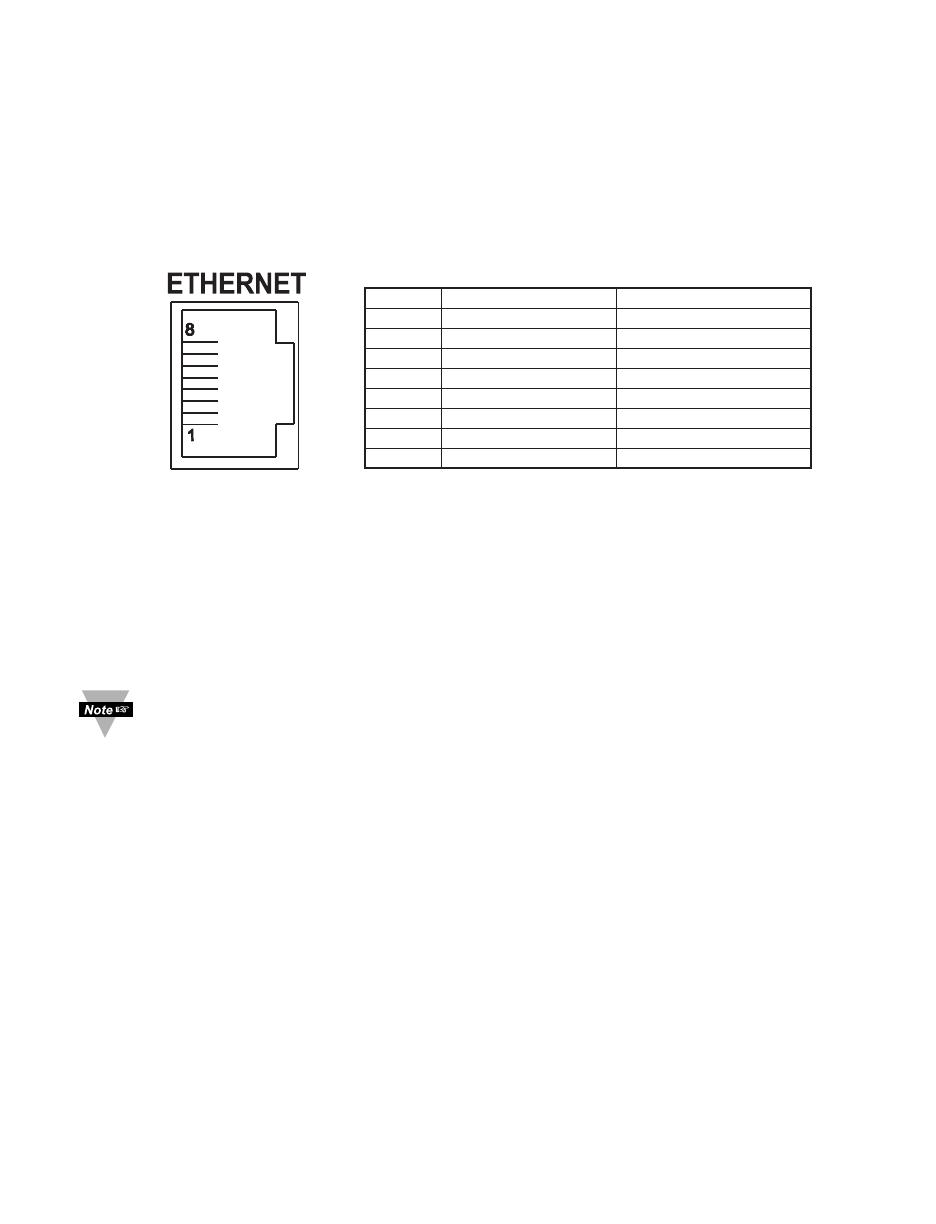
2.4.1 10BASE-T RJ-45 Pinout
The 10BASE-T Ethernet network system is used in the iServer for network connectivity.
The 10 Mbps twisted-pair Ethernet system operates over two pairs of wires. One pair is
used for receiving data signals and the other pair is used for transmitting data signals.
This means that four pins of the eight-pin connector are used.
Figure 2.3 RJ-45 Pinout
2.4.2 Connecting iServer to PC/Hub/Switch/Router
The iServer’s Ethernet interface can automatically detect the Rx and Tx lines on a
twisted pair Ethernet cable (MDI/MDIX Auto Cross). Therefore, to connect an iServer to a
PC/Hub/Switch/Router, either a straight-through or a cross-over cable can be used.
On certain devices (like iServer), it is possible for the hardware to automatically
correct errors in cable selection, making the distinction between a “straight-
through” cable and a “cross-over” cable unimportant. This capability is known as
“Auto MDI/MDIX”.
You may need to power recycle for auto detect to take place.
7
Pin Name Description
1 +Tx + Transmit Data
2 -Tx - Transmit Data
3 +RX + Receive Data
4 N/C Not Connected
5 N/C Not Connected
6 -Rx - Receive Data
7 N/C Not Connected
8 N/C Not Connected
PART 3
NETWORK CONFIGURATION
3.1 Network Protocols
The iServer can be connected to an Ethernet network using standard IP protocols
including TCP, UDP, SNMP, SMTP, ARP, HTTP (WEB server), DHCP, DNS, Telnet,
and Modbus TCP/IP.
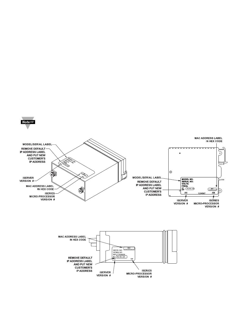
3.2 Ethernet (MAC) Address
MAC (Media Access Control) address is your computer's unique hardware number.
When you're connected to the LAN from your computer, a correspondence table relates
your IP address to your computer's physical (MAC) address. The MAC address can be
found on the label of your device and contains 6 bytes (12 characters) of hexadecimal
numbers XX:XX:XX:XX:XX:XX hex
For example: 0A:0C:3D:0B:0A:0B
Remove the small label with the default IP address and there will be room to put
your IP address. See Figure 3.1 thru Figure 3.3.
8
Figure 3.1 i8 - Labeling
Figure 3.3 i16 - Labeling
Figure 3.2 iDR - Labeling

3.3 DHCP
DHCP, Dynamic Host Configuration Protocol, enables computers and devices to
extract their IP configurations from a server (DHCP server).
If DHCP is enabled on your iServer, as soon as the iServer is connected to the
network, there is an exchange of information between the iServer and the DHCP
server. During this process the IP address, the Gateway address, and the Subnet
Mask, will be assigned to the iServer by the DHCP server. Note that the DHCP
server must be configured correctly to do such assignment.
The iServer is shipped with DHCP disabled (factory default).
If fixed or static IP address is desired, the DHCP function must be disabled.
The DHCP can be enabled by accessing the iServer’s web server and selecting
Network option (refer to Section 4.5.2).
1. It is very important to communicate with the network administrator in
order to understand DHCP and its existing configurations on the host
server, before enabling DHCP on the iServer.
2. The iServers are shipped with a default static IP address of
192.168.1.200 and Subnet Mask of 255.255.255.0.
3. On Windows servers where DHCP and DNS are separate functions it’s
very important to configure DHCP server to communicate with DNS in
order for the iServer’s Host Name to correctly respond. If you cannot
access the iServer using its Host Name, please contact your network
administrator to make sure DHCP and DNS servers are linked together.
3.4 DNS
DNS, Domain Name System enables computers and devices to be recognized over
a network based on a specific name instead of IP addresses.
For example, instead of having to use http://192.168.1.200 (IP address), you would
use only http://eit0a0b or any eight character name stored as Host Name under
Access Control menu in the iServer Home Page.
The default DNS name for an iServer is "eit" followed by the last four digits of the
MAC address of that particular iServer.
3.5 IP Address
Every active device connected to the TCP/IP network must have a unique IP
address. This IP address is used to build a connection to the iServer itself and the
serial device connected to the iServer’s serial port. All network devices like
computers that use TCP/IP protocol to communicate with each other should have a
unique 32-bit address called IP address.
The IP address is divided into two portions, the network ID and the host ID. For
instance, every computer on the same network uses the same network ID. At the
same time, all of them have different host IDs.
For more details about the IP address see Appendix B.
9

3.6 TCP Port (Socket) Number
All TCP connections are defined by an IP address and a port number. A port number
is an internal address that provides a TCP/IP interface between an application
software on a computer and a device on the network.
There are three default TCP port (socket) numbers assigned to the iServer:
1. Port 1000: Once a TCP connection is made to the iServer using port 1000, the
iServer will forward the connection to the serial device and it will take the
response from the serial device and send it out to the network.
2. Port 2000: Once a TCP connection is made to the iServer using port 2000 (or
any port number that is configured on the iServer), the iServer will forward the
connection to the serial device and it will take the response from the serial
device and send it out to the network.
3. Port 2002: This port is the iServer’s network console port for reading or
changing the iServer’s settings. This can be done using a Telnet application.
Example: C:\>Telnet 192.168.1.200 2002
10

PART 4
OPERATIONS
This iServer can be configured in several ways, depending on user’s preference and
network setup. It can be configured using a Web browser like Chrome, Internet Explorer,
or Firefox to access its Web server. It can also be configured using a TCP connection to
port 2002 using a command line interface. The iConnect Configuration Software can also
be used to find and configure the iServer over the Ethernet.
4.1 SERIAL INTERFACE CONFIGURATION - Communication Protocol
A data communication protocol defines the rules and structure of messages used by all
devices on a network for data exchange. A typical transaction will consist of a request to
send from the MASTER followed by the response from one or more SLAVE devices.
Either a single (point-to-point) or multi-drop network (multi-point) is possible.
4.2 Command Structure
There are different command types associated with communication between the
Ethernet Server and your device shown in Table 4.1, which shows the Command Prefix
Letters (Command Classes)
Table 4.1 Command Prefix Letters
COMMAND PREFIX
(COMMAND CLASS) MEANING
^AE Special read, Communication parameters
P (Put) Write HEX data into RAM
W (Write) Write HEX data into EEPROM.
G (Get) Read HEX data from RAM
R (Read) Read HEX data from EEPROM
U Read status byte
V Read measurement data string in decimal format
X Read measurement data values in decimal format
D Disable
E Enable
Z Reset
4.3 Command Formats
Table 4.2 shows the command formats for the Ethernet Server.
Table 4.2 Command Formats
For "P" and "W" Command For "G" and "R" Command For "X", "V", "U", "D", "E",
classes: classes: & "Z" Command classes:
Point-to-point mode Point-to-point mode Point-to-point mode
* ccc<data><cr> * ccc <cr> * ccc <cr>
Multi-point mode Multi-point mode Multi-point mode
* nnccc [<data>]<cr> * nnccc <cr> * nnccc <cr>
11

Where:
"*" is the selected Recognition Character. You may select any ASCII table symbol from
"!" (HEX address "21") to the right-hand brace (HEX "7D") except for the caret "^", "A",
"E", which are reserved for bus format request.
"ccc" stands for the hex-ASCII Command Class letter (one of eleven given in Table 4.1),
followed by the two hex-ASCII Command Suffix characters identifying the meter data,
features, or menu items to which the command is directed.
"<data>" is the string of characters containing the variable information the computer is
sending to the meter. These data (whether BCD or binary) are encoded into hex-ASCII
character (see Appendix D for binary-hex-ASCII chart), two characters to the byte.
Square brackets [indicating optional status] enclose this string, since some commands
contain no data.
"<nn>" are the two ASCII characters for the device Bus Address of RS485
communication.
Use values from "00" to hex "C7" (199 decimal).
The following format is used for each byte sent and received through serial port of
Ethernet Server:
1. Seven or Eight-bit binary, Hexadecimal (0 ... 9, A ... F)
2. Two hexadecimal characters contained in each eight-bit field of the message
3. 1 start bit; 7 or 8 data bit; 1 Stop Bit; Odd, Even (No Parity) Bit
The figure below shows the bit sequences when a byte is transmitted or received
through the Ethernet Server.
LSB MSB
LSB – Least Significant bit
MSB – Most Significant bit
Least Significant bit sent first
Refer to your device’s Serial Communication Manual for a list of Commands.
12
START 1 2 3 4 5 6 7 8 STOP PARITY
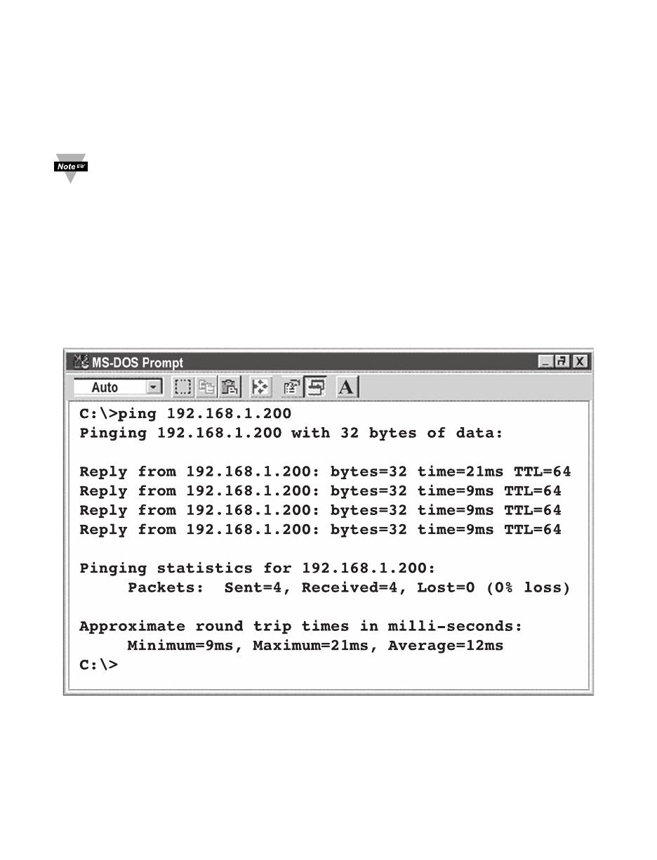
4.4 Default IP Address
The iServer is shipped with a default IP address of 192.168.1.200 and Subnet Mask
of 255.255.255.0. If you are going to use a Web browser or Telnet program to
access the iServer using its default IP address, make sure that the PC from which
you’re establishing the connection has an IP address that is in the same range as
the iServer’s IP address (192.168.1.x, where x can be any number from 1 to 254).
Your PC’s IP address cannot be the same as the iServer’s IP address.
You also need to make sure that your PC’s Subnet Mask is 255.255.255.0. This is a
good way to access the iServer over the network and make any configuration
changes needed.
If 192.168.1.200 is already in use on your network, connect the iServer directly to
your computer using a CAT5 Ethernet cable (either straight or cross-over cable will
be detected by the iServer) and proceed as described above.
To verify a good connection to the iServer, from a DOS prompt on your computer
type “ping 192.168.1.200” and press Enter. You should get a reply as shown in
Figure 4.1.
Figure 4.1 Pinging the iServer from a DOS Prompt
13

4.5 Access and Configuration Using a Web Browser
• Start your web browser.
• In the URL field, type http://192.168.1.200 (iServer’s default IP address)
• The iServer will display the LOGIN page, as shown below.
Figure 4.2 iServer LOGIN Page
In order to access iServer’s web pages, users may be prompted for a
password.
Figure 4.3 iServer LOGIN and ADMINISTRATOR Passwords
There are two different access levels:
1. LOGIN Password is required to access the iServer’s web server unless it’s
disabled. The default password is 12345678. This password can be up to 16
alphanumeric case-sensitive characters.
2. ADMINISTRATOR Password is required to access NETWORK, SECURITY, and
SYSTEM web pages, unless it’s disabled. The default password is 00000000.
This password can be up to 16 alphanumeric case-sensitive characters.
14
/