Page is loading ...

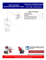
Discharge Valves
Installation, Operation, and Maintenance Instructions
Index
Operation Method
See Page
Type
Actuator
Valve
Size
Installation and Operation
Maintenance
Trouble-
shooting
Valve
Dimensions
Available
Operator
Positions
Panel Connection
Valve
Mounting
Drain and
Gauge Line
Connections
Pressure
Ratings
Description
Components
Manual
Override
Manual
Push-Pull
(1)
Without
Flowmeter
Provision
2-1/2 in.
2
3
15
Optional from
Waterous
See Pages
2 and 4
Not
Applicable
20
21
21
22
23
With
Flowmeter
Provision
2-1/2 in.
4
5
Remote
Locking
(1)
Drains 90° to
Water Flow
2-1/2 in.
6
8
15
Not Available
from Waterous
Drains 45° to
Water Flow
2-1/2 in.
7
Rotary Actuator
2-1/2 in.
9
11
15
16, 17
3-1/2 in.
10
Electric
Rotary Actuator
2-1/2 in.
12
14
15
18
19
3-1/2 in.
13
Note:
1) Push-Pull and Remote Locking Actuators are not available with 3-1/2 in. valves.
Waterous Company 125 Hardman Avenue South, South St. Paul, Minnesota 55075 (651) 450-5000
www.waterousco.com
Form Number: F-1031 Issue Date: 2/21/20
Section: 3007 Revision Date: 10/10/22

F-1031, Section 3007
Page 2 of 23
Valve Dimensions
Manual Push-Pull Actuator
Without Flowmeter Provision

F-1031, Section 3007
Page 3 of 23
Available Operator Positions
Manual Push-Pull Actuator
Without Flowmeter Provision

F-1031, Section 3007
Page 4 of 23
Valve Dimensions
Manual Push-Pull Actuator
With Flowmeter Provision

F-1031, Section 3007
Page 5 of 23
Valve Dimensions
Manual Push-Pull Actuator
With Flowmeter Provision

F-1031, Section 3007
Page 6 of 23
Valve Dimensions
Manual Remote Locking Actuator
Drains 90° to Waterflow

F-1031, Section 3007
Page 7 of 23
Valve Dimensions
Manual Remote Locking Actuator
Drains 45° to Waterflow

F-1031, Section 3007
Page 8 of 23
Available Operator Positions
Remote Locking Actuator

F-1031, Section 3007
Page 9 of 23
Valve Dimensions
Manual Rotary Actuator
2-1/2 in. Valve

F-1031, Section 3007
Page 10 of 23
Valve Dimensions
Manual Rotary Actuator
3-1/2 in. Valve

F-1031, Section 3007
Page 11 of 23
Available Operator Positions
Manual Rotary Actuator

F-1031, Section 3007
Page 12 of 23
Valve Dimensions
Electric Rotary Actuator
2-1/2 in. Valve

F-1031, Section 3007
Page 13 of 23
Valve Dimensions
Electric Rotary Actuator
3-1/2 in. Valve

F-1031, Section 3007
Page 14 of 23
Available Operator Positions
Electric Rotary Actuator

F-1031, Section 3007
Page 15 of 23
Panel Connection - Description
Push-Pull Operation:
The valve is operated by a .50 in. diameter control rod which can be locked in position by twisting the panel handle. The valve may be located
immediately behind the operator’s panel which Waterous calls “Panel” mounting. If the valve is to be operated from the panel opposite where
the valve is located, a universal joint is provided with the valve for connection of the operating rod. Waterous calls this “Remote Mounting”.
Installation requires a .50 in. diameter control rod and handle which the OEM furnishes. Note that 11.00 in. and 61.375 in. long rods and tee
handle kit are available from Waterous as optional items, see pages 2 and 4.
Note that Waterous offers numerous actuator positions relative to waterflow and push or pull open operation to satisfy necessary rod
operations, see page 3 for Push-Pull without Flowmeter and page 5 for Push-Pull with Flowmeter provision.
Remote Locking Operation:
The valve is operated by a separate OEM provided locking cable, rod or bell crank connected to the valve control arm. The valve may be
located anywhere behind the panel.
Note that Waterous offers eight control arm positions relative to waterflow and push or pull open operation to satisfy necessary rod operations,
see page 8.
Manual Rotary Actuator Operation:
See pages 16 and 17 for panel components. The valve is operated by a crank handle located on the operator’s panel which is connected to
the valve by a .50 in. diameter control rod. An indicating panel is also furnished which indicates the open-closed position of the valve.
Note that Waterous offers four actuator positions relative to waterflow and control rod connection location, see page 11.
Electric Rotary Actuator Operation:
See page 18 for panel components and page 19 for manual override. The valve is operated by an electric motor on the valve. A control panel
is furnished for opening and closing the valve which also indicates the open-closed position. The valve may be manually operated via a hex
nut on the valve’s electric motor.
Note that Waterous offers eight actuator positions relative to waterflow and manual override location, see page 14.
Note that it is normal for the valve to produce a ratcheting sound upon reaching the full open or completely closed position.

F-1031, Section 3007
Page 16 of 23
Manual Rotary Actuator
Panel Connection – Components

F-1031, Section 3007
Page 17 of 23
Manual Rotary Actuator
Panel Connection – Components

F-1031, Section 3007
Page 18 of 23
Electric Rotary Actuator
Panel Connection – Components

F-1031, Section 3007
Page 19 of 23
Electric Rotary Actuator
Manual Override

F-1031, Section 3007
Page 20 of 23
Valve Mounting
If the valves were not installed on the pump at the factory, follow the instruction below.
Stem Direction and Flow Direction:
All valves may be mounted with the stem up or at either side. This will allow for proper drainage of the valve. Mounting the
stem down is not recommended as the valve will not drain properly. All valves have a hydraulically balanced self-adjusting
seal which should be on the pump side of the installation.
Connection to Pump:
2-1/2 in. Valves:
1) Attach the separate flange furnished with the valve loosely to the pump flange using four bolts.
2) Coat the O-ring on the end of the valve with light grease or mineral oil.
3) Insert the discharge valve into the mounted flange and rotate enough to engage the lugs on the valve with slots in the flange. Tighten
the flange bolts to secure the valve.
4) Connect a drain line into the lowest tap on the valve body.
3-1/2 in. Valves:
1) Attach the valve directly to the pump flange using the gasket provided and eight bolts.
2) Connect a drain line to the lowest tap on the valve body.
In-line Valve Mounting (Threaded tap on each end of the valve):
If in-line mounting of the valve (threaded piping on each side of the valve) is required, contact Waterous Company for available tapped flanges
which can be installed on the valve.
/