Page is loading ...

C# 002354
VR70 Air Compressor
Installation Manual
John Deere JD6068
SYSTEM S700172


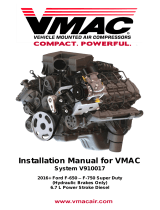
Installation Manual for
System S700172
John Deere 6068 VR70
General Information..................................................................... 3
Before You Start ....................................................................... 3
Part 1: System Identification and Warnings ............................ 4
Part 2: Air/Oil Separator Tank (AOST) Installation ................... 5
2.1 Preparing for Installation .................................................... 5
2.2 Tank Installation ................................................................. 7
Part 3: Manifold Installation ........................................................ 9
3.1 Installing the Bracket and Manifold .................................... 9
Part 4: Cooler Installation ........................................................... 11
Part 5: Installing the Compressor .............................................. 15
5.1 Main Bracket ....................................................................... 15
5.2 Installing Air End and Hoses .............................................. 17
4.3 Filling the System with Oil .................................................. 27
Part 6: Control System ................................................................ 29
6.1 Control Box and Wiring ...................................................... 30
6.2 Confirmation Test ............................................................... 31
Part 7: Finishing the Installation ................................................ 32
6.1 Before Starting the Engine Checklist.................................. 32
6.2 After Starting Engine Checklist ........................................... 32
Accessory Products from VMAC ............................................... 34
VMAC – Vehicle Mounted Air Compressors
Toll Free: 1-888-241-2289
Fax: 1-250-740-3201 1

!
!
Document #1930232
Installation Manual for VMAC System S700172
John Deere 6068 VR70
Changes and Revisions
Version
Revision Details
Revised by/date
Approved
Implemented
A ENGINEERING RELEASE RR 04NOV2014
MP/RD 10 Nov 2014
18 Nov 2014
B ECN 14-079: S700172
FASTENER PACK CHANGES RR 17NOV2014 MP/DB 19 Nov 2014 19 Nov 2014
Important Information
The information in this manual is intended for certified VMAC installers
who have been trained in installation procedures and for people with
mechanical trade certification who have the tools and equipment to
properly and safely perform the installation. Do not attempt this
installation if you do not have the appropriate mechanical training,
knowledge and experience.
Follow all safety precautions for underhood mechanical work. Any
grinding, bending or restructuring operations for correct fit in modified
vehicles must follow standard shop practices.
All hoses, tubes, and wires which are rerouted or shifted
during installation must be secure so that they do not
contact excessively hot areas or sharp edges. Where
possible follow the routing suggestions in this manual.
The VMAC warranty form is located at the back of this manual. This
warranty form must be completed and mailed or faxed to VMAC at the
time of installation for any subsequent warranty claim to be considered
valid.
To order parts, contact your VMAC dealer. Your dealer will ask for the
VMAC serial number, part number, description and quantity. To locate
your nearest dealer, call 1-888-241-2289.
VMAC recommends covering all hoses and wires for
protection.
Copyright 2013
All trademarks used in this manual are the property of the respective copyright holder.
The contents of this manual may not be reproduced in any form without the express
written permission of VMAC, 1333 Kipp Road, Nanaimo, BC V9X 1R3.
Printed in Canada
VMAC – Vehicle Mounted Air Compressors
Toll Free: 1-888-241-2289
Fax: 1-250-740-3201 2

General Information
Before You Start
Read this manual before attempting installation so that you can
familiarize yourself with the components and how they fit on the
vehicle. Identify variations for different engine models and different
situations that are listed in the manual. Open the package, unpack
the components and identify them.
All fasteners must be torqued to specifications. Use manufacturers
torque values for OEM fasteners. Apply Loctite 242 or equivalent
on all engine-mounted fasteners. Torque values are with Loctite
applied unless otherwise specified.
STANDARD GRADE 8 NATIONAL COARSE THREAD
Size
1/4
5/16
3/8
7/16
1/2
9/16
5/8
3/4
Foot-pounds (ft-lb)
9
18
35
55
80
110
170
280
Newton meter (N•m)
12
24
47
74
108
149
230
379
STANDARD GRADE 8 NATIONAL FINE THREAD
Size
3/8
7/16
1/2
5/8
3/4
Foot-pounds (ft-lb)
40
60
90
180
320
Newton meter (N•m)
54
81
122
244
434
METRIC CLASS 10.9
Size
M8
M10
M12
M14
M16
Foot-pounds (ft-lb)
19
41
69
104
174
Newton meter (N•m)
25
55
93
141
236
Hose Information
Different frame designations will affect the tank mounting position. If
you have to move the tank, the lines may be too short. Measure the
hose shortfall and order a Hose Extender Kit. Depending on other
installed equipment, it might be necessary to move the air/oil
separator tank from its intended location. The hoses used in VMAC
compressor systems have a specific inner liner that is
compatible with our compressor oil. Use of hoses other than
those supplied or recommended by VMAC may cause
compressor damage and may void your warranty. Please contact
VMAC for replacement hoses and further information.
VMAC – Vehicle Mounted Air Compressors
Toll Free: 1-888-241-2289
Fax: 1-250-740-3201 3

Part 1: System Identification and
Warnings
□ The System Identification Number Plate must be attached to the
equipment at the time of installation. This plate provides
information that allows VMAC to assist in customer inquiries and
ordering of parts
□ Mark and drill two 7/64-inch holes in a suitable location. This
location must be easily visible, such as beside the control box or
compressor. Secure the plate with the supplied self-tapping
screws
□ Place the S700172 belt routing and safety label beside the
control box in a visible location.
□ Complete the warranty form. The VMAC warranty form is located
within the system ID package as well as online at:
http://vmacair.com/support/warranty/
This warranty form must be completed and mailed or faxed to
VMAC at the time of installation for any subsequent warranty
claim to be considered valid.
VMAC – Vehicle Mounted Air Compressors
Toll Free: 1-888-241-2289
Fax: 1-250-740-3201 4

Part 2: Air/Oil Separator Tank
(AOST) Installation
2.1 Preparing for Installation
□ Remove the service panel on the alternator side of the
enclosure.
□ Remove the PTO offset housing, bracket, and associated oil
fittings (Figure 1) and plug/blank the ports (Figure 2).
Figure 1
REMOVE
VMAC – Vehicle Mounted Air Compressors
Toll Free: 1-888-241-2289
Fax: 1-250-740-3201 5


2.2 Tank Installation
□ Install the BRACKET, TANK MOUNT (1200761) and fasten to
the frame using the supplied fasteners (Figure 4).
Figure 4
□ While pulling the enclosure corner post outward, slide the AOST
into position. It is recommended that the tank is installed with
the welded bracket initially pointing upward and then rotated into
position once the tank is in the mounting location.
□ Install the (4) supplied fasteners securing the welded bracket on
the AOST to the frame (Figure 5).
□ Install the C-Clamp over the end of the AOST and loosely secure
the clamp to the frame with the supplied fasteners.
□ Install and tighten the pinch bolt on the clamp.
□ Tighten the previously installed fasteners securing the c-clamp to
the bracket.
MOUNTING
HOLES
1200761
VMAC – Vehicle Mounted Air Compressors
Toll Free: 1-888-241-2289
Fax: 1-250-740-3201 7

!
Figure 5
The tank must be mounted below the level of the
compressor discharge with the arrow on the end cap
pointing vertically upwards.
□ Remove the oil drain plug on the AOST.
□ Install the remote-oil drain hose and ball-valve assembly.
WELDED MOUNTING
BRACKET
C-CLAMP
VMAC – Vehicle Mounted Air Compressors
Toll Free: 1-888-241-2289
Fax: 1-250-740-3201 8

Part 3: Manifold Installation
3.1 Installing the Bracket and Manifold
□ Secure the bracket (1200801) to the top engine block as shown
in Figure 6.
Figure 6
□ Attach the bracket (1200796) to bracket (1200801) and secure
1200796 to the bottom engine block. The bolt goes through the
MANIFOLD
MOUNTING HOLES
TOP ENGINE
BLOCK BOLTS
M8x25
1200801
1200796
BOTTOM
BLOCK BOLT
M8x35 + spacer
VMAC – Vehicle Mounted Air Compressors
Toll Free: 1-888-241-2289
Fax: 1-250-740-3201 9


Part 4: Cooler Installation
□ Remove the (2) engine mount bolts (see Figure 8) and install the
lower cooler bracket re-using the same bolts. Leave the bolts
loose at this point.
□ Install the upper cooler bracket on the engine block using 2x
M10x110 bolts. Tighten the fasteners to the torque specified.
Figure 8
UPPER COOLER
BRACKET
MOUNTING HOLES
LOWER COOLER
BRACKET
MOUNTING HOLES
VMAC – Vehicle Mounted Air Compressors
Toll Free: 1-888-241-2289
Fax: 1-250-740-3201 11

□ Install the cooler between the two brackets in the orientation
shown in Figure 9 using the supplied fasteners in (6) places and
tighten to specification.
Figure 9
□ Tighten the fasteners securing the lower bracket to the engine
mount.
VMAC – Vehicle Mounted Air Compressors
Toll Free: 1-888-241-2289
Fax: 1-250-740-3201 12

!
Figure 10
□ Attach green wire with ring terminal from the cooler fan harness
to the ground post of the alternator as indicated in Figure 10.
□ Attach orange wire with ring terminal from the cooler fan harness
to the 24v post of the alternator as indicated in Figure 10.
□ Blunt cut orange wire from the fan harness connects to an
ignition switched 24v source.
Note: See Figure 11 for cooler-fan wiring schematic.
GROUND POST
24v POST
VMAC – Vehicle Mounted Air Compressors
Toll Free: 1-888-241-2289
Fax: 1-250-740-3201 13

Figure 11
VMAC – Vehicle Mounted Air Compressors
Toll Free: 1-888-241-2289
Fax: 1-250-740-3201 14


!
□ Remove the 3 side engine mounts and attach the L-shaped
bracket as shown in Figure 14.
Note: Leave the rear bottom bolt tight to hold engine
during installation.
Figure 14
□ Remove the tensioner assembly and idler from the main bracket.
□ Apply Loctite and re-install the tensioner assembly and the idler
on the main bracket and torque fasteners to specification.
REMOVE
UPPER FRONT
ENGINE MOUNT
LOWER FRONT
ENGINE MOUNT
VMAC – Vehicle Mounted Air Compressors
Toll Free: 1-888-241-2289
Fax: 1-250-740-3201 16

□ Mount the main bracket to the upper and lower front engine
mounts as shown in Figure 14.
□ Apply loctite and install the provided M16 bolts in the two front
block mounts. Do not tighten.
□ Snug down the (2X) M16 x 50mm engine mount bolts and torque
to specifications.
5.2 Installing Air End and Hoses
□ Install crank pulley. The pulley mounts between the OEM crank
pulley and the OEM damper. Use loctite and six M10x25mm
bolts provided and torque to specifications.
□ Mount the compressor to the main bracket. Use the two
M8x20mm bolts provided to mount the clutch bracket to the front
of the main bracket as shown in Figure 15.
Figure 15
M8 BOLTS
VMAC – Vehicle Mounted Air Compressors
Toll Free: 1-888-241-2289
Fax: 1-250-740-3201 17

□ Apply loctite and install compressor to main bracket using the
three M8 bolts. These bolts are of varying lengths and the
positions are shown in Figure 16 . Torque to specifications.
Figure 16
M8X90MM BOLT
M8X100MM BOLT
M8X30MM BOLT
VMAC – Vehicle Mounted Air Compressors
Toll Free: 1-888-241-2289
Fax: 1-250-740-3201 18
/