Page is loading ...

HUBBELL ELECTRICAL PRODUCTS
A Division of HUBBELL INCORPORATED (Delaware)
2112 Fenton Logistics Park Blvd
Fenton, Missouri 63026 USA
INSTALLATION, OPERATION &
MAINTENANCE DATA SHEET
SERIES EXB-N34 CEN & EXBLT-N4 CEN
SERIES EXB-N34 & EXBLT-N4
Empty Enclosures and Controllers
P/N KIL00911572 FORM No. K0983 R06/23 ECO-2-038-23 Page 1 of 9
CAUTION:
Before installing, make sure you are compliant with area classifications, as failure to do so may result in bodily injury, death and property damage. Do not attempt
installation until you are familiar with the following procedures. All installation must comply with the applicable Electrical Code(s).
Make sure that the circuit is de-energized before starting installation or maintenance.
Verify that the installation is grounded. Failure to ground will create electrical shock hazards, which can cause serious injury and or death.
This enclosure utilizes non-metallic components. The end user should consider their performance with respect to the chemicals that may be present in the
hazardous area.
IMPORTANT:
Please read these instructions carefully before installing or maintaining this equipment. Good electrical practices should be followed at all times and this data
should be used as a guide only.
Technical information, advice and recommendations contained in these documents is based upon information that Killark believes to be reliable. All the
information and advice contained in these documents is intended for use only by persons having been trained and possessing the requisite skill and know-how and
to be used by such persons only at their own discretion and risk. The nature of these instructions is informative only and does not cover all of the details, variations
or combinations in which this equipment may be used, its storage, delivery, installation, check out, safe operation and maintenance. Since conditions of use of the
product are outside of the care, custody and control of Killark, the purchaser should determine the suitability of the product for his intended use, and assumes all
risk and liability whatsoever in connection therewith.
QUANTUM ENCLOSURES /
(EXB-N34, EXBLT-N4, EXB-N34 CEN & EXBLT-N4 CEN Empty Enclosures and Controllers)
Classified by Underwriters Laboratories as to explosion and fire hazard only. Enclosure for use in Hazardous Locations.
UL and CSA certified for use in Class I, Groups B, C & D, Type 3, 4 & 4X, Class II, Groups E, F & G and Class III Hazardous
Locations, as defined by the Canadian Electrical Code and the National Electrical Code. IECEx / ATEX Certified for use in
Zone 1 & 2, Zone 21 & 22, Ex db IIB+H2 Gb, Ex tb IIIC Gb Hazardous Locations, IP66 Ingress Protection.
0518

HUBBELL ELECTRICAL PRODUCTS
A Division of HUBBELL INCORPORATED (Delaware)
2112 Fenton Logistics Park Blvd
Fenton, Missouri 63026 USA
INSTALLATION, OPERATION &
MAINTENANCE DATA SHEET
SERIES EXB-N34 CEN & EXBLT-N4 CEN
SERIES EXB-N34 & EXBLT-N4
Empty Enclosures and Controllers
P/N KIL00911572 FORM No. K0983 R06/23 ECO-2-038-23 Page 2 of 9
Application Information -
a: These component enclosures form the basis for certification of a unit or protection system for use in hazardous areas other than Zone 0.
b: All internal components mounted in this enclosure should be Certified (Listed Or Recognized) for the application and installed in accordance
with the component manufacturer's installation instructions.
c: Care shall be taken by the end-use Control Station manufacturer to ensure proper separation of circuits (voltages), and spacings (creepage
and clearance distances between live parts of opposite polarity, and between all live parts and dead metal) are maintained. Refer to
IEC/EN/UL/CSA 60079-7, Table 2, for minimum Increased Safety creepage and clearance distances.
d: A complete Control Station should be certified by a notified body to the applicable product safety Standard(s), and all supply wiring methods
(including grounding) shall be in accordance with the local/jurisdictional electrical code(s).
Installation Instructions -
NEC/CEC: This junction box must be installed by trained, qualified and competent personnel. Installation must comply with
local, state and national regulations, as well as safety practices for this type of equipment.
IEC/EN Installation Code references (60079-14, 60079-17) : Installation shall be carried out by suitably-trained personnel in
accordance with the applicable code of practice e.g. IEC/EN 60079-14.
The mounting location must be flat and provide proper clearance, rigidity and strength to support the enclosure and all
contained devices. (Refer to Figures 1 & 2)
WARNING: Electrical power must be OFF during installation. Disconnect primary power source and lock out.
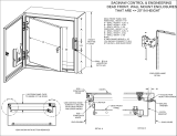
Larger enclosures are equipped with factory installed hinges. Enclosure should be mounted with hinges on the left. Do not mount
the enclosure with hinges on the top or bottom side. (See Figure 3)
Securely fasten the enclosure to the mounting location, using M12 or 1/2” diameter steel mounting bolts and washers, or washer
head bolts. Install sealing fittings and conduit using an approved electrical conducting type lubricant on the threads. The conduit
thread connections must be tapered pipe thread conforming to ANSI/ASME B1.20.1.
A minimum of five (5) full threads engagement is required for all NPT device connections/ threaded openings. A minimum of
seven (7) full threads engagement is required for all NPSM/Metric device connections/ threaded openings.
Sealing fittings, approved for the specific hazardous location where the enclosure is used, must be installed within 18” of the
enclosure for NEC/CEC Class and Division applications. For ATEX, IECEx, & UKCA applications, the seal must be immediately
adjacent to the enclosure. See schedule of limitations for deviation allowances.
All unused enclosure openings must be plugged using a certified close-up plug approved for the specific hazardous location where
the enclosure is used. Plugs must be tightly installed with a minimum engagement of five (5) full threads for NPT threads, and
seven (7) full threads for NPSM/Metric threads.
IMPORTANT: When installing cover-mounted components into component Series EXB and EXBLT enclosures, install only
IECEx/ATEX certified auxiliary control devices for hazardous locations (such as Killark Series GO operators) with Long and Extra-
Long shafts only. Refer to individual operator installation sheet for installation details. The minimum wall thickness of counter-
bore (where required) and operator spacing are to be determined from the dimensional chart on Page 6.
NOTE: If installing a breather and/or drain, make certain they are suitable for the specific hazardous location where they are to
be used. Also, installing a breather rated Type 4 or IPx6 will reduce the need to provide a protective device to shield the breather
and drain during hose-down operations.

HUBBELL ELECTRICAL PRODUCTS
A Division of HUBBELL INCORPORATED (Delaware)
2112 Fenton Logistics Park Blvd
Fenton, Missouri 63026 USA
INSTALLATION, OPERATION &
MAINTENANCE DATA SHEET
SERIES EXB-N34 CEN & EXBLT-N4 CEN
SERIES EXB-N34 & EXBLT-N4
Empty Enclosures and Controllers
P/N KIL00911572 FORM No. K0983 R06/23 ECO-2-038-23 Page 3 of 9
Installation Instructions (cont’d) -
Inspect and clean the machined flange flame joint surfaces of both the cover and box. Surfaces must be smooth, free of nicks,
scratches, dirt or any foreign particle build-up that would prevent a proper seal. Surfaces must seat fully against each other to
provide a proper explosion-proof joint. Clean surfaces by wiping with a clean, lint-free cloth.
Apply a light coat of Killark “LUBG” lubricant to flange surfaces and close the cover. Install and tighten all cover bolts to 40Nm
(30 ft. lbs.). Make certain no cover bolts are omitted. Use only those bolts supplied with the enclosure. Check the bolted joint
with a .0381mm (.0015”) thick feeler gauge. The gauge must not enter the joint more than 3.175mm (1/8”) at any point.
NOTE: Missing bolts or an improper joint can result in an explosion, creating a potential for physical injury or property damage.
Maintenance Instructions –
Inspection and maintenance of this equipment shall be carried out by suitably
trained personnel in accordance with the applicable code of practice e.g. IEC/EN 60079-17.
After installation, this junction box should be inspected at regular intervals. A visual inspection should ascertain that all cover
bolts are installed and still tight; that all conduit connections are intact and free of corrosion, and that the enclosure mounting
bolts are tight and in good condition.
If the enclosure must be opened for servicing, to check or replace internal devices and apparatus, the following procedures should
be followed.
WARNING: Before servicing the enclosure, be certain the electrical power is OFF. Disconnect the enclosure from primary power
source and lock out.
Remove all cover bolts. Clean and inspect. Replace any corroded, bent or otherwise damaged bolts with new, factory authorized
bolts obtained from an authorized Killark distributor.
Open enclosure. Do not use a hammer, screwdriver or any prying tool to open cover, except as shown in Figure 4.
Inspect cover hinges. If hinges are
damaged or do not function properly, contact a factory authorized service representative for
hinge replacement and installation.
Inspect machined, flame joint flange surfaces. Surfaces must be smooth, free of nicks, scratches, dirt or any foreign particle build-
up that would prevent a proper seal. Should surface be damaged, contact factory. Never attempt to rework surfaces by sanding,
grinding, etc. Surfaces must seat fully against each other to provide a proper explosion-proof joint.
Inspect water exclusion gasket. If gasket is damaged, contact Killark Customer Service (1-800-KILLARK) for replacement gasket
and instructions on repair.
Contact a factory authorized representative for a replacement cover. When removing gasketed cover for replacement, do not
detach hinge body from cover. It should be detached at the back-box.
Remove cover and hinge body from enclosure by removing the hinge pins. (See Figure 5) The damaged gasket can be removed
from the cover and the cover without ga
sket can be safely used in Class I & II hazardous (classified) locations, however, the
enclosure may not be raintight or hosedown tight.
Clean flange surfaces by wiping with a clean, lint-free cloth. Apply a light coating of Killark “LUBG” lubricant to flange surfaces and
close cover. Install and tighten all cover bolts to 40Nm (30 ft. lbs.). Make certain no cover bolts are omitted. Use only factory
authorized bolts. Check the flame joint with a .0381mm (.0015”) thick feeler gauge. The gauge must not enter the flame joint
more than 3.175mm (1/8”) at any point.
Missing bolts or an improper flame joint can result in an explosion, creating a potential for physical injury and property damage.

HUBBELL ELECTRICAL PRODUCTS
A Division of HUBBELL INCORPORATED (Delaware)
2112 Fenton Logistics Park Blvd
Fenton, Missouri 63026 USA
INSTALLATION, OPERATION &
MAINTENANCE DATA SHEET
SERIES EXB-N34 CEN & EXBLT-N4 CEN
SERIES EXB-N34 & EXBLT-N4
Empty Enclosures and Controllers
P/N KIL00911572 FORM No. K0983 R06/23 ECO-2-038-23 Page 4 of 9
Certification Ratings -
Series EXB and EXBLT Empty (Component) Enclosures : Series EXB and EXBLT Control Stations :
North American Certifications (UL / CSA – Series EXB only):
HazLoc Ratings: Class I, Div. 1, Groups B, C and D; Class II, Div. 1,
Groups E, F and G; Class III, Div. 1; Encl. Types 3 and 4 (Cat. Nos.
ending in N34 & N4).
UL: -25°C ≤ T ambient ≤ 60°C
CSA: -50°C ≤ T ambient ≤ 60°C
North American Certifications (cCSAus):
HazLoc Ratings: Class I, Div. 1, Groups B, C and D; Class II,
Div. 1, Groups E, F and G; Class III, Div. 1; Encl. Types 3 and
4 (Cat. Nos. ending in N34 & N4).
UL: -25°C ≤ T ambient ≤ 60°C
CSA: -50°C ≤ T ambient ≤ 60°C
ATEX / IECEx/UKCA ratings :
II 2 G Ex db IIB+H2 Gb
II 2 D Ex tb IIIC Db IP66
QPS21ATEX0001U / IECEx QPS 17.0013U
-50oC ≤ T ambient ≤ +70oC
3CT22UKEX1002U
ATEX / IECEx/UKCA ratings :
0518 II 2 G Ex db IIB+H2 Gb
II 2 D Ex tb IIIC T90oC Db IP66
QPS21ATEX0002(X) / IECEx QPS 17.0014X
-50oC ≤ T ambient ≤ +70oC
3CT22UKEX1003X
IECEx/ATEX Schedule of limitations –
1) Rectangular windows larger than 2 x 4 in. have been evaluated only to the low risk of mechanical danger and are certified for
use in an ambient temperatures range of -20 OC to +70 OC.
2) Round windows larger than 5-3/8 in. have been evaluated only to the low risk of mechanical danger and are certified for use in
an ambient temperatures range of -20 OC to +70 OC.
3) Enclosures sealed within 18 inches are certified for use in an ambient temperature range of -20
O
C to +70
O
C.
Figure 1 :

HUBBELL ELECTRICAL PRODUCTS
A Division of HUBBELL INCORPORATED (Delaware)
2112 Fenton Logistics Park Blvd
Fenton, Missouri 63026 USA
INSTALLATION, OPERATION &
MAINTENANCE DATA SHEET
SERIES EXB-N34 CEN & EXBLT-N4 CEN
SERIES EXB-N34 & EXBLT-N4
Empty Enclosures and Controllers
P/N KIL00911572 FORM No. K0983 R06/23 ECO-2-038-23 Page 5 of 9
Figure 2 :
Figures 3, 4, 5 :

HUBBELL ELECTRICAL PRODUCTS
A Division of HUBBELL INCORPORATED (Delaware)
2112 Fenton Logistics Park Blvd
Fenton, Missouri 63026 USA
INSTALLATION, OPERATION &
MAINTENANCE DATA SHEET
SERIES EXB-N34 CEN & EXBLT-N4 CEN
SERIES EXB-N34 & EXBLT-N4
Empty Enclosures and Controllers
P/N KIL00911572 FORM No. K0983 R06/23 ECO-2-038-23 Page 6 of 9
ABC D E F G H I J K L M N O P Q R S T U V W X Y Z
EXB-664 N34 5.00 5.00 3.00 3.00 5.73 5.73 4.31 10.31 10.31 6.09 N/A 4.00 7.88 N/A 0.19 1.18 2.81 2.44 4.88 2.75 2.81 2.44 4.88 2.5 5.00 5.00 0.50 2.5 420 EXB-664 N34
EXB-684 N34 5.00 7.00 3.00 5.00 5.75 7.75 4.18 10.25 12.25 6.12 N/A 4.00 7.88 N/A 0.19 1.18 2.81 3.44 6.88 2.75 2.81 2.44 4.88 2.5 7.00 5.00 0.50 2.5 621 EXB-684 N34
EXB-6124 N34 5.00 11.00 3.00 9.00 5.75 11.75 4.25 10.68 16.68 7.00 N/A 7.82 7.88 N/A 0.19 1.18 2.81 5.00 10.00 2.75 2.81 2.44 4.88 2.5 11.00 5.00 0.88 2.5 843 EXB-6124 N34
EXB-886 N34 7.00 7.00 5.00 5.00 7.59 7.59 6.06 12.31 12.31 8.09 N/A 6.00 9.88 N/A 0.19 1.18 4.81 3.44 6.88 3.75 4.81 3.44 6.88 2.5 7.00 7.00 0.63 2.5 933 EXB-886 N34
EXB-8104 N34 7.00 9.00 5.00 7.00 7.73 9.73 4.06 12.31 14.31 6.32 N/A 8.00 9.88 N/A 0.19 1.18 2.81 4.44 8.88 2.75 2.81 3.44 6.88 2.5 9.00 7.00 0.82 2.5 12 36 EXB-8104 N34
EXB-8106 N34 7.00 9.00 5.00 7.00 7.59 9.59 6.06 12.31 14.31 8.32 N/A 8.00 9.88 N/A 0.19 1.18 4.18 4.44 8.88 3.45 4.81 3.44 6.88 2.5 9.00 7.00 0.82 2.5 12 40 EXB-8106 N34
EXB-8126 N34 7.00 11.00 5.00 9.00 8.00 12.00 6.38 13.25 17.25 8.70 3.82 7.82 10.38 14.38 0.19 1.78 3.75 5.00 10.00 3.66 3.75 3.00 6.00 2.5 11.00 7.00 0.75 2.5 12 60 EXB-8126 N34
EXB-8128 N34 7.00 11.00 5.00 9.00 8.00 12.00 8.38 13.25 17.25 10.70 3.82 7.82 10.38 14.38 0.19 1.78 5.75 5.00 10.00 4.66 5.75 3.00 6.00 2.5 11.00 7.00 0.75 2.5 12 64 EXB-8128 N34
EXB-10106 N34 9.00 9.00 7.00 7.00 10.00 10.00 6.20 15.25 15.25 8.90 4.94 4.94 12.94 12.94 0.25 1.91 3.75 4.00 8.00 3.79 3.75 4.00 8.00 2.5 9.00 9.00 1.00 2.5 12 66 EXB-10106 N34
EXB-10108 N34 9.00 9.00 7.00 7.00 10.00 10.00 8.20 15.25 15.25 10.90 4.94 4.94 12.94 12.94 0.25 1.91 5.75 4.00 8.00 4.79 5.75 4.00 8.00 2.5 9.00 9.00 1.00 2.5 12 73 EXB-10108 N34
EXB-10146 N34 9.00 13.00 7.00 11.00 10.00 14.00 6.20 15.25 19.25 8.90 4.94 8.94 12.94 16.94 0.25 1.91 3.75 6.00 12.00 3.79 3.75 4.00 8.00 2.5 13.00 9.00 1.00 2.5 15 82 EXB-10146 N34
EXB-10148 N34 9.00 13.00 7.00 11.00 10.00 14.00 8.20 15.25 19.25 10.90 4.94 8.94 12.94 16.94 0.25 1.91 5.75 6.00 12.00 4.79 5.75 4.00 8.00 2.5 13.00 9.00 1.00 2.5 15 91 EXB-10148 N34
EXB-12126 N34 10.50 10.50 9.00 9.00 11.50 11.50 6.00 16.37 16.37 8.69 6.94 6.94 14.94 14.94 0.25 1.88 3.81 4.94 9.88 4.00 3.81 4.94 9.88 2.5 10.00 10.00 1.08 2.5 16 79 EXB-12126 N34
EXB-12128 N34 10.50 10.50 9.00 9.00 11.37 11.37 8.00 16.37 16.37 10.69 6.94 6.94 14.94 14.94 0.25 1.88 5.81 4.94 9.88 5.00 5.81 4.94 9.88 2.5 10.00 10.00 1.08 2.5 16 80 EXB-12128 N34
EXB-12186 N34 10.00 16.00 9.00 15.00 11.50 17.50 6.00 16.37 22.38 9.06 6.94 12.88 14.94 20.88 0.25 2.06 3.13 7.94 15.88 3.88 3.75 4.94 9.88 2.5 16.00 10.00 1.25 2.5 28 104 EXB-12186 N34
EXB-12188 N34 10.00 16.00 9.00 15.00 11.37 17.37 8.00 16.37 22.38 11.06 6.94 12.88 14.94 20.88 0.25 2.06 5.13 7.94 15.88 4.88 5.75 4.94 9.88 2.5 16.00 10.00 1.25 2.5 28 113 EXB-12188 N34
EXB-12246 N34 10.25 22.25 9.00 21.00 11.50 23.50 6.00 16.37 28.38 9.32 6.94 18.88 14.94 26.88 0.25 2.13 3.13 10.94 21.88 3.94 3.81 4.94 9.88 2.5 22.25 10.25 1.44 2.5 36 139 EXB-12246 N34
EXB-12248 N34 10.25 22.25 9.00 21.00 11.37 23.37 8.00 16.37 28.38 11.32 6.94 18.88 14.94 26.88 0.25 2.13 5.13 10.94 21.88 4.94 5.81 4.94 9.88 2.5 22.25 10.25 1.44 2.5 36 151 EXB-12248 N34
EXB-122412 N34 10.25 22.25 9.00 21.00 11.37 23.37 12.00 16.37 28.38 15.32 6.94 18.88 14.94 26.88 0.25 2.13 9.13 10.94 21.88 6.94 9.81 4.94 9.88 2.5 22.25 10.25 1.44 2.5 36 176 EXB-122412 N34
EXB-12368 N34 11.00 35.00 9.00 33.00 12.00 36.00 8.12 17.25 41.25 11.40 7.00 31.00 15.00 39.00 0.25 2.09 5.75 17.00 34.00 4.97 5.75 5.00 10.00 2.5 35.00 11.00 1.31 2.5 56 229 EXB-12368 N34
EXB-123610 N34 11.00 35.00 9.00 33.00 12.00 36.00 10.12 17.25 41.25 13.40 7.00 31.00 15.00 39.00 0.25 2.09 7.75 17.00 34.00 5.97 7.75 5.00 10.00 2.5 35.00 11.00 1.31 2.5 56 245 EXB-123610 N34
EXB-14146 N34 13.00 13.00 11.00 11.00 14.00 14.00 6.20 19.25 19.25 9.40 9.00 9.00 17.00 17.00 0.25 2.09 3.75 6.00 12.00 3.97 3.75 6.00 12.00 2.5 13.00 13.00 1.31 2.5 25 111 EXB-14146 N34
EXB-14148 N34 13.00 13.00 11.00 11.00 14.00 14.00 8.20 19.25 19.25 11.40 9.00 9.00 17.00 17.00 0.25 2.09 5.75 6.00 12.00 4.97 5.75 12.00 24.00 2.5 13.00 13.00 1.31 2.5 25 121 EXB-14148 N34
EXB-16166 N34 14.00 14.00 13.00 13.00 15.50 15.50 6.00 20.38 20.38 9.19 10.94 10.94 18.94 18.94 0.25 2.06 3.75 6.94 13.88 4.18 3.75 6.94 13.88 2.5 14.00 14.00 1.38 2.5 36 128 EXB-16166 N34
EXB-16168 N34 14.00 14.00 13.00 13.00 15.37 15.37 8.00 20.38 20.38 11.19 10.94 10.94 18.94 18.94 0.25 2.06 5.75 6.94 13.88 5.18 5.75 6.94 13.88 2.5 14.00 14.00 1.38 2.5 36 139 EXB-16168 N34
EXB-16248 N34 15.00 23.00 13.00 21.00 16.00 24.00 8.12 21.25 29.25 12.00 11.38 19.38 19.38 27.38 0.25 2.34 5.75 11.00 22.00 5.22 5.75 7.00 14.00 2.5 22.00 14.00 1.63 2.5 40 237 EXB-16248 N34
EXB-162410 N34 15.00 23.00 13.00 21.00 16.00 24.00 10.12 21.25 29.25 14.00 11.38 19.38 19.38 27.38 0.25 2.34 7.75 11.00 22.00 6.22 7.75 7.00 14.00 2.5 22.00 14.00 1.63 2.5 40 248 EXB-162410 N34
EXB-18186 N34 17.00 17.00 15.00 15.00 18.00 18.00 6.12 23.25 23.25 10.00 13.38 13.38 21.38 21.38 0.25 2.34 3.75 8.00 16.00 4.22 3.75 8.00 16.00 2.5 16.00 16.00 1.63 2.5 36 195 EXB-18186 N34
EXB-18188 N34 17.00 17.00 15.00 15.00 18.00 18.00 8.12 23.25 23.25 12.00 13.38 13.38 21.38 21.38 0.25 2.34 5.75 8.00 16.00 5.22 5.75 8.00 16.00 2.5 16.00 16.00 1.63 2.5 36 212 EXB-18188 N34
EXB-18248 N34 16.38 22.13 15.00 21.00 17.37 23.37 8.00 22.38 28.38 11.75 13.00 19.00 21.00 27.00 0.25 2.32 4.88 10.94 21.88 5.00 5.56 7.94 15.88 2.5 22.00 16.00 1.69 2.5 63 235 EXB-18248 N34
EXB-182410 N34 16.38 22.13 15.00 21.00 17.23 23.23 10.00 22.38 28.38 13.75 13.00 19.00 21.00 27.00 0.25 2.32 6.88 10.94 21.88 6.00 8.56 7.94 15.88 2.5 22.00 16.00 1.69 2.5 63 251 EXB-182410 N34
EXB-18308 N34 16.00 19.00 15.00 28.00 17.87 30.80 8.00 22.37 35.37 12.37 13.25 26.50 21.00 34.50 0.25 2.50 4.88 14.44 28.88 5.18 6.06 7.94 15.90 2.5 29.00 16.00 2.07 2.5 77 317 EXB-18308 N34
EXB-18368 N34 16.00 34.00 15.00 33.00 17.37 35.37 8.00 22.38 40.38 12.38 13.25 31.50 21.25 39.50 0.25 2.50 4.88 16.94 33.88 5.18 6.06 7.94 15.88 2.5 34.00 16.00 2.07 2.5 78 366 EXB-18368 N34
EXB-183610 N34 16.00 34.00 15.00 33.00 17.23 35.23 10.00 22.38 40.38 14.38 13.25 31.50 21.25 39.50 0.25 2.50 6.88 16.94 33.88 6.18 8.06 7.94 15.88 2.5 34.00 16.00 2.07 2.5 78 394 EXB-183610 N34
EXB-203611 N34 18.75 34.75 16.75 32.75 20.14 36.14 11.13 26.44 42.44 15.56 15.75 31.75 23.75 39.75 0.25 2.47 8.44 16.72 33.97 6.88 8.47 8.72 17.47 2.5 34.88 18.88 2.08 2.5 91 493 EXB-203611 N34
EXB-24248 N34 22.25 22.25 21.00 21.00 23.37 23.37 8.06 28.38 28.38 12.19 19.50 19.50 27.50 27.50 0.25 2.88 5.50 10.88 21.88 5.88 5.50 10.94 21.88 2.5 22.00 22.00 1.94 2.5 81 323 EXB-24248 N34
EXB-242410 N34 22.25 22.25 21.00 21.00 23.23 23.23 10.06 28.38 28.38 14.19 19.50 19.50 27.50 27.50 0.25 2.88 7.50 10.88 21.88 6.88 7.50 10.94 21.88 2.5 22.00 22.00 1.94 2.5 81 342 EXB-242410 N34
EXB-24308 N34 23.00 29.00 21.00 27.00 24.00 30.00 8.12 28.38 35.25 12.40 19.56 25.56 27.56 33.56 0.25 2.47 5.75 14.00 28.00 5.35 5.75 11.00 22.00 3.0 28.00 22.00 1.97 2.5 70 442 EXB-24308 N34
EXB-24368 N34 23.00 35.00 21.00 33.00 24.00 36.00 8.12 29.25 41.25 12.40 19.56 31.56 27.56 39.56 0.25 2.47 5.75 17.00 34.00 5.35 5.75 11.00 22.00 3.0 34.00 22.00 1.88 2.5 77 478 EXB-24368 N34
EXB-243610 N34 23.00 35.00 21.00 33.00 24.00 36.00 10.12 29.25 41.25 14.40 19.56 31.56 27.56 39.56 0.25 2.47 7.75 17.00 34.00 6.35 7.75 11.00 22.00 3.0 34.00 22.00 1.88 2.5 77 507 EXB-243610 N34
ENCLOSURE
CATALOG
NUMBER
UNIT
WGT
(lbs)
ENCLOSURE
CATALOG
NUMBER
INTERNAL DIMENSIONS
EXTERNAL
DIMENSIONS
MOUNTING
DIMENSIONS
CONDUIT
AREA
OPERATOR AREA
SPECIFICATION
MIN THK.
AT C'BORE
MAX.
DIA.
C'BORE
MAX.
# OF
OPER.
PAN
INTERNAL VOLUME

HUBBELL ELECTRICAL PRODUCTS
A Division of HUBBELL INCORPORATED (Delaware)
2112 Fenton Logistics Park Blvd
Fenton, Missouri 63026 USA
INSTALLATION, OPERATION &
MAINTENANCE DATA SHEET
SERIES EXB-N34 CEN & EXBLT-N4 CEN
SERIES EXB-N34 & EXBLT-N4
Empty Enclosures and Controllers
P/N KIL00911572 FORM No. K0983 R06/23 ECO-2-038-23 Page 7 of 9
AB C DE F GHI J KL M N O PQR S TU V WX Y Z
EXBLT-664 N4 5.00 5.00 335.73 5.73 4.00 10.31 10.31 5.94 N/A 4.00 7.88 N/A 0.19 1.18 2.81 2.32 4.63 2.75 2.81 2.31 4.63 2.5 5.00 5N/A N/A 4
17 EXBLT-664 N4
EXBLT-684 N4 5.00 7.00 355.75 7.75 4.00 10.25 12.25 5.94 N/A 4.00 7.88 N/A 0.19 1.18 2.81 3.32 6.63 2.75 2.81 2.31 4.63 2.5 7.00 5N/A N/A 6
20 EXBLT-684 N4
EXBLT-686 N4 5.00 7.00 3 5 5.75 7.75 6.00 10.25 12.25 7.94 N/A 4.00 7.88 N/A 0.19 1.18 4.18 3.25 6.50 3.75 4.81 2.25 4.50 2.5 7.00 5N/A N/A 6
23 EXBLT-686 N4
EXBLT-6124 N4 5.00 11.00 395.75 11.75 4.00 10.68 16.68 5.88 N/A 7.82 7.88 N/A 0.19 1.18 2.81 5.44 10.88 2.75 2.81 2.44 4.88 2.5 11.00 5N/A N/A 8
29 EXBLT-6124 N4
EXBLT-6126 N4 5.00 11.00 395.75 11.75 6.00 10.68 16.68 7.88 N/A 7.82 7.88 N/A 0.19 1.18 4.18 5.38 10.75 3.75 4.81 2.38 4.75 2.5 11.00 5N/A N/A 8
32 EXBLT-6126 N4
EXBLT-886 N4 7.00 7.00 557.59 7.59 6.00 12.31 12.31 7.94 N/A 6.00 9.88 N/A 0.19 1.18 4.81 3.25 6.50 3.75 4.81 3.25 6.50 2.5 7.00 7N/A N/A 9
27 EXBLT-886 N4
EXBLT-8104 N4 7.00 9.00 577.73 9.73 4.00 12.31 14.31 5.94 N/A 8.00 9.88 N/A 0.19 1.18 2.81 4.32 8.63 2.75 2.81 3.32 6.63 2.5 9.00 7N/A N/A 12
28 EXBLT-8104 N4
EXBLT-8106 N4 7.00 9.00 5 7 7.59 9.59 6.00 12.31 14.31 7.94 N/A 8.00 9.88 N/A 0.19 1.18 4.18 4.25 8.50 3.45 4.81 3.25 6.50 2.5 9.00 7N/A N/A 12
31 EXBLT-8106 N4
EXBLT-9116 N4 8.00 10.00 689.00 11.00 6.00 13.31 15.31 7.94 N/A 7.50 10.88 N/A 0.19 1.18 4.18 4.75 9.50 3.45 4.81 3.75 7.50 2.5 9.00 7N/A N/A 12
40 EXBLT-9116 N4
EXBLT-8126 N4 7.00 11.00 598.00 12.00 6.00 13.25 17.25 8.01 3.82 7.82 10.38 14.38 0.19 1.78 3.75 5.00 10.00 3.66 3.75 3.00 6.00 2.5 11.00 7N/A N/A 12
47 EXBLT-8126 N4
EXBLT-8128 N4 7.00 11.00 5 9 8.00 12.00 8.00 13.25 17.25 10.01 3.82 7.82 10.38 14.38 0.19 1.78 5.75 4.94 9.88 4.66 5.75 2.94 5.88 2.5 11.00 7N/A N/A 12
52 EXBLT-8128 N4
EXBLT-10106 N4 9.00 9.00 7710.00 10.00 6.00 15.25 15.25 8.19 4.94 4.94 12.94 12.94 0.25 1.91 3.75 4.00 8.00 3.79 3.75 4.00 8.00 2.5 9.00 9N/A N/A 12
49 EXBLT-10106 N4
EXBLT-10108 N4 9.00 9.00 7710.00 10.00 8.00 15.25 15.25 10.19 4.94 4.94 12.94 12.94 0.25 1.91 5.75 3.94 7.88 4.79 5.75 3.94 7.88 2.5 9.00 9N/A N/A 12
54 EXBLT-10108 N4
EXBLT-10146 N4 9.00 13.00 711 10.00 14.00 6.00 15.25 19.25 8.19 4.94 8.94 12.94 16.94 0.25 1.91 3.75 6.00 12.00 3.79 3.75 4.00 8.00 2.5 13.00 9N/A N/A 15
60 EXBLT-10146 N4
EXBLT-10148 N4 9.00 13.00 711 10.00 14.00 8.00 15.25 19.25 10.19 4.94 8.94 12.94 16.94 0.25 1.91 5.75 5.94 11.88 4.79 5.75 3.94 7.88 2.5 13.00 9N/A N/A 15
65 EXBLT-10148 N4
EXBLT-12126 N4 10.50 10.50 9 9 11.50 11.50 6.00 16.37 16.37 8.19 6.94 6.94 14.94 14.94 0.25 1.88 3.81 4.69 9.38 4.00 3.81 4.69 9.38 2.5 10.00 10 N/A N/A 16
56 EXBLT-12126 N4
EXBLT-12128 N4 10.50 10.50 9911.37 11.37 8.00 16.37 16.37 10.19 6.94 6.94 14.94 14.94 0.25 1.88 5.81 4.63 9.25 5.00 5.81 4.63 9.25 2.5 10.00 10 N/A N/A 16
61 EXBLT-12128 N4
EXBLT-12186 N4 10.00 16.00 915 11.88 17.88 6.00 16.38 22.38 8.44 6.94 12.88 14.94 20.88 0.25 2.06 3.13 7.94 15.88 3.88 3.75 4.94 9.88 2.5 16.00 10 N/A N/A 28
82 EXBLT-12186 N4
EXBLT-12188 N4 10.00 16.00 915 11.88 17.88 6.00 16.38 22.38 10.44 6.94 12.88 14.94 20.88 0.25 2.06 5.13 7.94 15.88 4.88 5.75 4.94 9.88 2.5 16.00 10 N/A N/A 28
89 EXBLT-12188 N4
EXBLT-12246 N4 10.25 22.25 921 11.88 23.88 6.00 16.38 28.38 8.57 6.94 18.88 14.91 26.88 0.25 2.13 3.13 10.94 21.88 3.94 3.81 4.94 9.88 2.5 22.25 10.3 N/A N/A 36 110 EXBLT-12246 N4
EXBLT-12248 N4 10.25 22.25 921 11.88 23.88 6.00 16.38 28.38 10.57 6.94 19.88 14.91 26.88 0.25 2.13 5.13 10.94 21.88 4.94 5.81 4.94 9.88 2.5 22.25 10.3 N/A N/A 36 122 EXBLT-12248 N4
EXBLT-122412 N4 10.25 22.25 921 11.88 23.88 12.00 16.38 28.38 14.69 6.94 20.88 14.91 26.88 0.25 2.13 9.13 10.94 21.88 6.94 9.81 4.94 9.88 2.5 22.25 10.3 N/A N/A 36 157 EXBLT-122412 N4
EXBLT-14146 N4 13.00 13.00 11 11 14.50 14.50 6.00 19.25 19.25 8.44 9.00 9.00 17.00 17.00 0.25 2.09 3.75 6.00 12.00 3.97 3.75 6.00 12.00 2.5 13.00 13 N/A N/A 25 82 EXBLT-14146 N4
EXBLT-14148 N4 13.00 13.00 11 11 14.50 14.50 8.00 19.25 19.25 10.44 9.00 9.00 17.00 17.00 0.25 2.09 5.75 6.00 12.00 4.97 5.75 6.00 12.00 2.5 13.00 13 N/A N/A 25 88 EXBLT-14148 N4
EXBLT-14248 N4 13.00 22.25 11 21 14.50 24.50 8.00 19.25 29.25 10.57 9.00 19.38 17.00 27.38 0.25 2.09 5.75 11.00 22.00 4.97 5.75 6.00 12.00 2.5 22.00 16 N/A N/A 45 142 EXBLT-14248 N4
EXBLT-14308 N4 13.00 29.00 11 27 14.50 30.50 8.00 19.25 35.25 10.57 9.00 26.25 17.00 34.25 0.25 2.09 5.75 14.44 28.88 4.97 5.75 6.00 12.00 2.5 29.00 16 N/A N/A 55 166 EXBLT-14308 N4
EXBLT-16166 N4 14.00 14.00 13 13 15.88 15.88 6.00 20.38 20.38 8.44 10.94 10.94 17.19 18.94 0.25 2.06 3.75 6.94 13.88 4.18 3.75 6.94 13.88 2.5 14.00 14 N/A N/A 36 91 EXBLT-16166 N4
EXBLT-16168 N4 14.00 14.00 13 13 15.88 15.88 8.00 20.38 20.38 10.44 10.94 11.94 17.19 18.94 0.25 2.06 5.75 6.94 13.88 5.18 5.75 6.94 13.88 2.5 14.00 14 N/A N/A 36 98 EXBLT-16168 N4
EXBLT-16248 N4 14.50 23.00 13 21 16.50 24.50 8.00 21.25 29.25 10.69 10.94 19.38 19.38 27.38 0.25 2.34 5.75 11.00 22.00 5.22 5.75 7.00 14.00 2.5 22.00 14 N/A N/A 40 166 EXBLT-16248 N4
EXBLT-162410 N4 14.50 23.00 13 21 16.50 24.50 10.00 21.25 29.25 12.69 10.94 19.38 19.38 27.38 0.25 2.34 7.75 11.00 22.00 6.22 7.75 7.00 14.00 2.5 22.00 14 N/A N/A 40 182 EXBLT-162410 N4
ENCLOSURE
CATALOG
NUMBER
MAX.
# OF
OPER.
UNIT
WGT
(lbs)
PAN
INTERNAL VOLUME
ENCLOSURE
CATALOG
NUMBER
INTERNAL DIMENSIONS
EXTERNAL
DIMENSIONS
MOUNTING
DIMENSIONS
CONDUIT
AREA
OPERATOR AREA
SPECIFICATION
MIN THK.
AT
C'BORE
MAX.
DIA.
C'BORE

HUBBELL ELECTRICAL PRODUCTS
A Division of HUBBELL INCORPORATED (Delaware)
2112 Fenton Logistics Park Blvd
Fenton, Missouri 63026 USA
INSTALLATION, OPERATION &
MAINTENANCE DATA SHEET
SERIES EXB-N34 CEN & EXBLT-N4 CEN
SERIES EXB-N34 & EXBLT-N4
Empty Enclosures and Controllers
P/N KIL00911572 FORM No. K0983 R06/23 ECO-2-038-23 Page 8 of 9
Electrical Maintenance Instructions
Electrical Data:
Rated Voltage: Up to 690 Volts Rated Current: 1000 Amps
Maximum Conductor Size: 500 mm2 (1000MCM) Maximum
Pilot Devices and Operating Handle Assemblies: Killark’s “G” series pilot devices and “EXH / B7” series operating handles may be
factory or field assembled in this enclosure. The installation of pilot devices, operating handles and internal components must
comply to the spacing requirements in FIGURE 6. The Killark factory must do the machining for operators and handles. Other
manufacturers’ pilot devices which are certified “Ex d” components per EN 60079-1 may be used.
Fuses: If fuses are installed, an external caution label must be provided with the following information: “Change fuse in the de-
energized state only. Use *** Volt ** Amp (class) Fuse.”
Batteries: Operation of batteries and storage of batteries in this enclosure must be such that short-circuits, overload and
overcharging are avoided. Components that are fed by the internal voltage source are to be covered by a safe-to-touch method. An
external caution label must be provided with the following marking: “Attention: Internal Voltage Source.”
Heat Producing components: If components are installed inside the enclosure that have a surface temperature above the
temperature class, an external caution label must be provided with the following marking: “Attention: Hot surfaces in the interior.
Open housing only after a waiting time of 15 minutes.”
Capacitors: When capacitors are installed in the enclosure, the energy for group IIB is limited to 0.06mJ (VDE 0165, section 6.1.5) by
the appropriate protective elements.
FIGURE 6: “EXB/EXBLT” ENCLOSURE / DEVICE SPACING

HUBBELL ELECTRICAL PRODUCTS
A Division of HUBBELL INCORPORATED (Delaware)
2112 Fenton Logistics Park Blvd
Fenton, Missouri 63026 USA
INSTALLATION, OPERATION &
MAINTENANCE DATA SHEET
SERIES EXB-N34 CEN & EXBLT-N4 CEN
SERIES EXB-N34 & EXBLT-N4
Empty Enclosures and Controllers
P/N KIL00911572 FORM No. K0983 R06/23 ECO-2-038-23 Page 9 of 9
MAXIMUM WATTAGE CHART
Power loss when used in temperature class T6 and T5 are as follows;
Enclosure T6 Max
Watts
T5 Max
Watts Enclosure T6 Max
Watts
T5 Max
Watts
EXB/EXBLT-664
95
135
EXB/EXBLT-14146
280
385
EXB/EXBLT-886
130
185
EXB/EXBLT-14148
315
465
EXB/EXBLT -8104
130
185
EXB/EXBLT-16166
315
460
EXB/EXBLT -8106
155
225
EXB/EXBLT-16168
340
500
EXB/EXBLT -8126
185
270
EXB/EXBLT-16248
495
735
EXB/EXBLT -8128
205
310
EXB/EXBLT-162410
530
785
EXBLT-9116
185
270
EXB-18186
400
585
EXB/EXBLT -10106
195
280
EXB-18188
440
650
EXB/EXBLT -10108
210
310
EXB-18248
495
740
EXB/EXBLT -10146
235
335
EXB-182410
535
790
EXB/EXBLT -10148
255
380
EXB-18368
685
1020
EXB/EXBLT -12126
205
310
EXB-183610
725
1085
EXB/EXBLT -12128
240
350
EXB-203611
870
1300
EXB/EXBLT-12186
280
385
EXB-24248
610
910
EXB/EXBLT-12188
315
465
EXB-242410
650
975
EXB/EXBLT-12246
350
500
EXB-24308
650
975
EXB/EXBLT-12248
385
565
EXB-24368
850
1265
EXB/EXBLT-122412
495
740
EXB-243610
900
1350
EXB-12368
550
795
EXB-123610
590
875
/