Installation and technical data CAN-PCI/360 Rev. 1.3
CAN-PCI/360
PCI-CAN-Interface
Hardware Installation
and
Technical Data

Installation and technical data CAN-PCI/360 Rev. 1.3
Document file: I:\texte\Doku\MANUALS\CAN\PCI\360\Englisch\PCI3613H.en9
Date of print: 05.02.2002
PCB-version: CAN-PCI/360 Rev. 1.1
Changes in the chapters
The changes in the document listed below affect changes in the hardware as well as changes in the
description of facts only.
Chapter Changes compared to previous version
-Editorial revision.
- -
Technical details are subject to change without further notice.

Installation and technical data CAN-PCI/360 Rev. 1.3
N O T E
The information in this document has been carefully checked and is believed to be entirely reliable. esd
makes no warranty of any kind with regard to the material in this document, and assumes no
responsibility for any errors that may appear in this document. esd reserves the right to make changes
without notice to this, or any of its products, to improve reliability, performance or design.
esd assumes no responsibility for the use of any circuitry other than circuitry which is part of a product
of esd gmbh.
esd does not convey to the purchaser of the product described herein any license under the patent rights
of esd gmbh nor the rights of others.
esd electronic system design gmbh
Vahrenwalder Str. 207
30165 Hannover
Germany
Phone: +49-511-372 98-0
Fax: +49-511-372 98-68
E-mail: [email protected]
Internet: www.esd-electronics.com
USA / Canada
7667 W. Sample Road
Suite 127
Coral Springs, FL 33065
USA
Phone: +1-800-504-9856
Fax: +1-800-288-8235
E-mail: [email protected]

Installation and technical data CAN-PCI/360 Rev. 1.3 1
Contents
1. Overview .................................................................3
1.1 Description of the Module ..................................................3
1.2 PCB View with Connector Assignment ........................................4
2. Hardware Installation .......................................................5
3. Description of Units .........................................................7
3.1 Microcontroller 68360 ..................................................... 7
3.2 DRAM-Equipping ........................................................8
3.3 Timekeeper .............................................................8
3.4 CAN-Interfaces ..........................................................9
3.5 Serial Interfaces ..........................................................9
3.6 The Multiplex Bus ........................................................9
4. Summary of Technical Data ................................................. 10
4.1 General Technical Data ................................................... 10
4.2 Microcontroller ......................................................... 11
4.3 Memory Units .......................................................... 11
4.4 Timekeeper ............................................................ 12
4.5 PCI-Bus .............................................................. 12
4.6 CAN-Interface .......................................................... 13
4.7 Software Support ....................................................... 13
4.8 Order Information ....................................................... 14
5. Connector Assignment of CAN-Bus Interfaces .................................. 15
5.1 CAN-Interfaces ......................................................... 15
5.1.1 CAN-Interfaces at 9-pin DSUB-Connectors (X701, X711) .................. 16
5.1.2 DeviceNet Option ................................................. 17
5.1.3 Optional CAN-Interfaces 2 and 3 ...................................... 18
5.2 Serial Interface 4 ........................................................ 19
5.2.1 RS-232-Interface at 10-Pin Post Connector X601 ......................... 19
5.2.2 RS-232-Interface at 9-pin DSUB-Socket ................................ 20
5.2.3 Option: RS-422, RS-485, TTY-Active/Passive ........................... 21
5.3 Serial Interfaces 1...3 ..................................................... 22
5.4 Multiplex-Interface at X900 ................................................ 23
6. Correctly Wiring Electrically Insulated CAN Networks ........................... 24
7. Circuit Diagrams .......................................................... 27

Installation and technical data CAN-PCI/360 Rev. 1.32
This page is intentionally left blank.

Overview
Installation and technical data CAN-PCI/360 Rev. 1.3 3
Microcontroller
68360
+5 V=
+5 V=
+5 V=
+5 V=
C
A
N
B
U
S
CAN
CAN
C
A
N
B
U
S
+5 V=
+5 V=
CAN
C
A
N
B
U
S
Physical
CAN
Layer
DC/DC-
Wandler
+5 V=
+5 V=
CAN
C
A
N
B
U
S
Physical
CAN
Layer
DC/DC-
Wandler
Flash EPROM
PCI Card Edge Connector
DRAM
4...32 MByte
QSPAN
CA91860
(32-bit Interface)
I²C
EEPROM
I²C
EEPROM
RS-232 Interface
(Option: RS-422,
RS-485, TTY)
3 serial Interfaces
(TTL Level) or
Ethernet (TTL)
30-pole
SMD Connector
10-pole
Post Connector
Physical
CAN
Layer
electrical isolation
DC/DC
Converter
DSUB9
CiA pinning
CAN Controller
SJA1000
electrical isolation
DC/DC
Converter
CAN Controller
SJA1000
Physical
CAN
Layer
DSUB9
CiA pinning
2nd CAN Interface
only at
CAN-PCI/360-2 34-pole
Post Connector
Multiplex
Bus Interface
electrical isolation
DSUB9
CiA pinning
4th CAN Interface
only at
CAN-PCI/360-4
CAN Controller
SJA1000
Ribbon
Cable
10-pole
Post Conector
electrical isolation
DSUB9
CiA pinning
3rd CAN Interface
only at
CAN-PCI/360-3
CAN Controller
SJA1000
Ribbon
Cable
10-pole
Post Conector
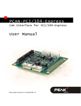
1. Overview
1.1 Description of the Module
Fig. 1.1.1: Block circuit diagram of the CAN-PCI/360 module
The module CAN-PCI/360 is a PC-plug-in board for the PCI-bus. It operates with a 68360
microcontroller which is responsible for the local management of CAN-data.
The module can be equipped with four equal CAN-interfaces. Two interfaces are connected directly by
means of 9-pin DSUB-connectors on board, the other two by means of two further DSUB-connectors
which are installed in a separate slot sheet. The CAN-data is buffered in a local DRAM. Data safety and
data consistency of up to 1 Mbit/s are guaranteed.

Overview
Installation and technical data CAN-PCI/360 Rev. 1.34
The CAN-interface, compatible to ISO11898, allows a data transfer rate of up to 1 Mbit/s. Like many
other properties of the CAN-interfaces, the bit rate can be configured by means of software. The CAN-
interface is electrically insulated from other voltage potentials.
In standard option the module has also got an RS-232 interface, an add-on slot by means of which the
68360 controller ports for three further serial interfaces or an Ethernet interface can be connected, as
well as a multiplex-bus interface for the option to connect peripheral units in the future.
1.2 PCB View with Connector Assignment
Fig. 1.2.1: Module view (diagram without fastening device and handle)

Installation
Installation and technical data CAN-PCI/360 Rev. 1.3 5
2. Hardware Installation
Attention!
Electrostatic discharge can damage electronical components. In order to prevent this, please
follow the steps below before touching the CAN-module to discharge the static electricity of
your body:
@Switch off the power supply of your PC, but leave it connected to mains.
@Please touch the metal case of the PC now to discharge yourself.
@Furthermore you should prevent to touch the CAN-module with your clothes, because these
can be charged electrostatically as well.
Installation procedure:
1. Switch off the PC and all connected peripheral devices (monitor, printer, etc.). Additionally,
switch off all other CAN-devices to whose network the CAN-module is to be connected in this
procedure.
2. Discharge the electrostatic electricity of your body as described above.
3. Disconnect the PC from mains.
4. Remove the PC case.
In order to remove the PC case a few screws have to be removed at the back of the PC in most
cases.
5. Select an available PCI-bus plug-in space and remove the plug-in cover at the back of the PC case.
The CAN-module can be plugged into any plug-in slot. Please take care not to plug it into an ISA-
plug-in slot accidentally, because this can damage both PC and the CAN-module!
The plug-in cover is secured with a screw. Please keep the screw after you have removed it,
because you will need it to secure the module.
5.1 Only for more than two CAN-interfaces:
If your module has got three or four CAN-interfaces, you have select an available plug-in slot to
which the slot sheet for the additional CAN-interfaces is to be installed. Please remove the plug-in
cover and keep the screw.
6. Plug the CAN-module into the selected PCI-plug-in slot.
Please push the module carefully into the slot until it clicks in.
@@

Installation
Installation and technical data CAN-PCI/360 Rev. 1.36
7. Secure the module.
Please use the screw removed from the plug-in cover for this (see step 5).
7.1 Only for more than two CAN-interfaces:
Install the slot sheet with the DSUB-connectors for CAN-interfaces 2 (and 3) and secure it with
the screw (see step 5.1). Plug the connectors of the flat ribbon cables into the post connectors on
board: The cable of the lower DSUB-connectors into X821, and the cable of the upper DSUB-
connector into X831.
Attention: The flat ribbon cables must not be plugged into post connectors X300 or X601!
Risk of damage!
8. Close the PC.
Secure the case with the according screws at the back.
9. Connect the CAN-bus.
Please remember that the CAN-bus has to be terminated at both ends. esd offers T-connectors and
terminators. Additionally, the CAN-GND-signal has to be grounded at exactly one point in the
CAN-network. Therefore the CAN-termination connectors have got a grounding contact. A CAN-
device whose CAN-interface is not electrically insulated corresponds to the grounding of the
CAN-GND.
The first CAN-interface (CAN-network 0) is connected by means of the lower DSUB-connector
(X701), and the second CAN-interface (CAN-network 1) is connected by means of the upper
DSUB-connecter (X711).
If applicable: The third CAN-interface (CAN-network 2) is connected by means of the lower
DSUB-connector and the additional slot sheet, and the fourth CAN-interface (CAN-network 3)
is connected by means of the upper DSUB-connector.
10. Connect your PC to mains again.
11. Switch on the PC, the peripheral devices and the other CAN-bus devices.
12. End of hardware installation.
For the software installation an installation program is available which is described in the software
manual of the module called ‘CAN-API, Software Tools and Installation Notes’..

Technical Data
Installation and technical data CAN-PCI/360 Rev. 1.3 7
3. Description of Units
3.1 Microcontroller 68360
The address position of the local units can be programmed in the microcontroller. The following table
represents the wiring of units with the chip-select signals of the controller.
Signal name in
circuit diagram 68360-chip-select
signal Unit
CS-F* CS0*(CSBOOT*) Flash EPROM
RAS1* CS1* DRAM-module
RAS2* CS2*
CS-C* CS3*
CAN-interface
(is divided into the lines CS-C0* to CS-
C3* by means of the address lines A8 and
A9 to select one of the four possible CAN-
interfaces)
CS-EXT* CS4* extension bus
CS-T* CS5* timekeeper
CSREG* CS6* register channel of the QSpan
IMSEL CS7* image select of he QSPan
Table 3.1.1: Assignment of chip-select lines
The microcontroller also allows other masters, such as the PCI-controller (Qspan), to access the units.
Accesses of the microcontroller 98360 with A32=1 lead to the PCI-bus.

Technical Data
Installation and technical data CAN-PCI/360 Rev. 1.38
3.2 DRAM-Equipping
The DRAM-module is controlled by means of the memory controller integrated in the microcontroller
68360. The multiplexing of address lines, however, is the responsibility of its own multiplexers to make
the DRAM also accessible for external PCI-bus masters. The composition of address pairs by the
multiplexer has been selected in a way that the DRAM-module can also be controlled in page mode.
The following table shows the capacities of DRAM-modules which can be used and the formation of
address pairs.
Buffer capacity Address pairs DRAM address
row address column address
1 Mbyte
2 Mbyte A11 A2 MA2
A12 A3 MA3
A13 A4 MA4
A14 A5 MA5
A15 A6 MA6
A16 A7 MA7
A17 A8 MA8
A18 A9 MA9
A19 A10 MA10
4 Mbyte
8 Mbyte A20 A21 MA11
16 Mbyte
32 Mbyte A22 A23 MA12
64 Mbyte
128 Mbyte A24 A25 MA13
Table 3.5.1: Formation of address pairs
3.3 Timekeeper
The timekeeper offers battery-buffered memory capacity in SRAM-technology. As an additional
function it has got an internal counter with a time basis of one second. The quartz required for this has
been integrated into the case of the battery which can be plugged on. The counter format corresponds
to the date and time coded in BCD format with separate values for year, month, day, weekday, hour,
minute and second. These values are read by reading accesses to particular address areas.
The eight data lines of the timekeeper are connected to the local data lines D24...D31 of the
microcontroller 68360.

Technical Data
Installation and technical data CAN-PCI/360 Rev. 1.3 9
3.4 CAN-Interfaces
In standard option the CAN-PCI/360 is available with four CAN-interfaces in accordance with
ISO11898. The interfaces are accessible via DSUB-connectors. Alternatively, CAN-interfaces 0 and
1 are also available as DeviceNet interfaces. Each CAN- or DeviceNet interface is electrically insulated
from the other units and has got a separate CAN-controller (SJA1000).
3.5 Serial Interfaces
An RS-232 interface is available for the communication withe the microcontroller 68360 (fourth
interface of the 68360). It is connected via a 10-pin post connector.
Optionally the interface is also available with other physical interfaces (RS-422, RS-485 or TTY). This
option has to be specified when the CAN-PCI/360 module is ordered, because it cannot be added later.
The microcontroller ports for serial interfaces 1 to 3 are accessible via a 30-pin SMD-socket strip (type:
SAMTEC CLT-115-02-F-D-A). The socket strip has been designed for the mounting of an add-on
board. Three drilled holes are available to secure such an add-on board.
3.6 The Multiplex Bus
In order to leave the option to access the local bus externally for coming tests or applications, the CAN-
PCI/360 module has got a so-called multiplex bus. It offers a 16-bit wide path to the data bus, 24
address lines, 5 interrupt lines and all control lines required to access a bus multiplexed on 34 connector
pins (X900).

Technical Data
Installation and technical data CAN-PCI/360 Rev. 1.310
4. Summary of Technical Data
4.1 General Technical Data
Ambient temperature 0...55 /C
Humidity max. 90%, non-condensing
Power supply via PCI-bus,
nominal voltage: 5 V ±5%,
current (typical at 20°C): 570 mA
Connectors
X100 (card edge) - PCI-bus
X600 (30-pin SMD-socket strip) -
add-on plug-in slot for serial interfaces 1...3
X601 (10-pin post connector) -
RS-232-interface (serial interface 4)
X602A,X602B (8-pin socket strips) -
piggyback plug-in slot as alternative to RS-232
interface
X700, X710 (8-pin SMD-socket strips) -
plug-in slots for DeviceNet-adapter
X701 (DSUB9/male) - CAN-network 1
X711 (DSUB9/male) - CAN-network 0
X800, X801, X802 (8-pin SMD-socket strips) -
CAN-controller interface at microcontroller
X821 (DSUB9/male) - optional CAN-network 2
X831 (DSUB9/male) - optional CAN-network 3
X900 (34-pin post connector) - multiplex bus
The following connectors are only used for programming or
testing:
X300 (10-pin post connector ) - BDM-interface
X400 (8-pin contact strip) - ISP-programming
Dimensions 106.68 mm x 312.0 mm (+28 mm handle)
Weight ca. 250 g
Table 4.1.1: General data of the module

Technical Data
Installation and technical data CAN-PCI/360 Rev. 1.3 11
4.2 Microcontroller
Type 68360
Cycle frequency 25 MHz
Data/address bus 32 bit data width, 32 bit address bus
Interrupts 7 IRQ-inputs
Memory management internal memory controller with DRAM-interface
and eight chip select outputs
Serial controller up to four serial interfaces,
optional Ethernet interface
Further features interface for direct connection of a serial EEPROM,
background debug mode
Table 4.2.1: Microcontroller data
4.3 Memory Units
FLASH-EPROM data bus: 8 bits
memory capacity: 1 Mbyte
DRAM
SIMM-module, flat in socket
data bus: 32 bits
memory capacity: standard: 16 Mbyte
max.: 128 Mbyte
access time: 60 ns
Serial EEPROMs
EEPROM at microcontroller 68360
memory capacity: 1 kbyte
EERPOM at PCI-controller
memory capacity: 256 kbyte
Table 4.3.1: Technical data of memory units

Technical Data
Installation and technical data CAN-PCI/360 Rev. 1.312
4.4 Timekeeper
Type SGS-Thomson M48T58Y
Memory SRAM 8k x 8 bits
Time basis 1 second
Time format 24 hours BCD-format
Time deviation ±35 ppm (±1.53 minute/month)
±4 ppm (with set calibration bit)
Data consistency ca. 7 years at 25°C ambient temperature
Table 4.4.1: Data of time keeper
4.5 PCI-Bus
Host bus PCI-bus in accordance with PCI Local Bus Specification 2.1
PCI-data bus 32 bits
Controller QSpan CA91C860, external serial EEPROM
Interrupt interrupt signal A
Plug-in position no restrictions in plug-in position,
PCI-bridges are tolerated
Board dimension Long Card
Connector PCI-Card-Edge-Connector
Table 4.5.1: PCI-bus data

Technical Data
Installation and technical data CAN-PCI/360 Rev. 1.3 13
4.6 CAN-Interface
Number 1,
optionally up to 4 CAN-interfaces
CAN-controller one SJA1000 for each CAN-network
CAN-protocol Basic-CAN 2.0A/B
Physical interface physical layer in accordance with ISO 11898 or DeviceNet,
transmission rate can be programmed from 10 kbit/s to
1 Mbit/s
Bus termination has to be set externally
Wiring
CAN-network 0: DSUB9 (X701) in slot cover of PCB
CAN-network 1: DSUB9 (X711) in slot cover of PCB
CAN-network 2: DSUB9 (X821) in separate slot cover
CAN-network 3: DSUB9 (X831) in separate slot cover
Electrical insulation of CAN-
interface from other units
the two possible CAN-interfaces are electrically insulated from
the PCI-bus potential by means of optical couplers and
DC/DC-converters
DeviceNet option
an adapter board each for CAN-channels 0 and 1 with Phoenix
Combicon connectors (or equivalent), optical couplers and
CAN-drivers in accordance with DeviceNet specification
‘DeviceNet Communication Model and Protocol, Rel. 2.0’
Table 4.6.1: Data of the CAN-interface
4.7 Software Support
The product package contains software examples for DOS (Library) and Windows 3.11 (DLL).
Additionally, software drivers for Windows NT/2000/XP and Windows 9x/ME are available. The
Windows-NT driver is in kernel mode and is multiprocessor steady. The Windows-9x/ME driver is
realised as VxD. The firmware can be loaded from PC into the Flash-EPROM.
Software packages are available for CANopen and DeviceNet.

Technical Data
Installation and technical data CAN-PCI/360 Rev. 1.314
4.8 Order Information
Type Features Order No.
CAN-PCI/360-2 2x CAN 2.0 A/B, ISO11898,
16 Mbyte DRAM C.2022.04
CAN-PCI/360-4 4x CAN 2.0 A/B, ISO11898, 16 Mbyte DRAM, incl.
additional slot cover with DSUB-connectors and flat-
ribbon cables C.2022.06
DN-PCI/360-2 2x DeviceNet,
16 Mbyte DRAM C.2022.08
Options:
CAN-PCI/360-95 Windows 95 VxD driver C.2022.10
CAN-PCI/360-NT Windows NT Device driver C.2022.11
CAN-PCI/360-Co CANopen Master/Slave-Obj. licence C.2022.12
CAN-PCI/360-ME *) English user manual for C.2022.04 ... C.2022.08 C.2022.21
CAN-API-ME *) English user manual for C.2022.10 and C.2022.11 C.2001.21
CAL/CANopen-ME *) English user manual for C.2022.12 C.2002.21
*) If product and manual are ordered together, the manual is free of charge.
Table 4.8.1: Order information

Connector Assignment
Installation and technical data CAN-PCI/360 Rev. 1.3 15
5. Connector Assignment of CAN-Bus Interfaces
5.1 CAN-Interfaces
The CAN-interfaces are divided onto the connectors as follows:
CAN-interface Connector
CAN-network 0
CAN-network 1
CAN-network 2
CAN-network 3
DSUB9: X701 (lower)
DSUB9: X711 (upper)
post connector (X821) to DSUB9 in separate slot cover (lower)
post connector (X831) to DSUB9 in separate slot cover (upper)

Connector Assignment
Installation and technical data CAN-PCI/360 Rev. 1.316
5.1.1 CAN-Interfaces at 9-pin DSUB-Connectors (X701, X711)
The position of signals in connectors of the CAN-network is identical. The connectors are 9-pin male
DSUB-connectors.
Pin Position:
Pin Assignment:
Signal Pin Signal
1reserved
CAN_GND 62CAN_L
CAN_H 73CAN_GND
reserved 84reserved
reserved 95shield
9-pin male DSUB-connector
Signal Description:
CAN_L, CAN_H... CAN-signal lines
CAN_GND ... reference potential of the local CAN-physical layer
shield ... potential of the connector case
reserved ... reserved for future applications

Connector Assignment
Installation and technical data CAN-PCI/360 Rev. 1.3 17
1
2
3
4
5
5.1.2 DeviceNet Option
If a CAN-channel of the module has got a DeviceNet interface, the respective DSUB-connector is not
available.
5-pin Phoenix-Combicon connectors MSTB 2.5/-GF-5.08 (or equivalent) are used as DeviceNet
connectors.
Pin Position: Pin Assignment:
Pin Signal
1V-
2CAN-
3Shield
4CAN+
5V+
Signal Description:
V+... power supply for the CAN-interface (UVCC = 24 V ± 4%)
V-... reference potential for V+ and CAN+/CAN-
CAN+, CAN-... CAN-signals
Shield... shield
(connected to ground (front panel) via a high-impedance RC-combination (1MS,
10nF/500V))
Page is loading ...
Page is loading ...
Page is loading ...
Page is loading ...
Page is loading ...
Page is loading ...
Page is loading ...
Page is loading ...
Page is loading ...
Page is loading ...
/