Page is loading ...

Instructions – Parts List
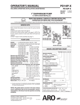
POLYPROPYLENE AND PVDF
Huskyt 1590 Air-Operated
Diaphragm Pumps
1.5–inch AODD pump for fluid transfer applications. For professional
use only.
Not approved to European explosive atmosphere requirements.
See Models on page 2 for a list of pump models and descriptions.
120 psi (0.84 MPa, 8.4 bar) Maximum Fluid Working Pressure
120 psi (0.84 MPa, 8.4 bar) Maximum Air Input Pressure
308549ZAD
EN
Important Safety Instructions
Read all warnings and instructions in
this manual. Save these instructions.
04700B

2 308549
Table of Contents
Models 2. . . . . . . . . . . . . . . . . . . . . . . . . . . . . . . . . . . . . . . .
Safety Warnings 3. . . . . . . . . . . . . . . . . . . . . . . . . . . . . .
Installation 5. . . . . . . . . . . . . . . . . . . . . . . . . . . . . . . . . . . . .
Operation 12. . . . . . . . . . . . . . . . . . . . . . . . . . . . . . . . . . . .
Maintenance 13. . . . . . . . . . . . . . . . . . . . . . . . . . . . . . . . . .
Troubleshooting 14. . . . . . . . . . . . . . . . . . . . . . . . . . . . . . .
Service
Repairing the Air Valve 16. . . . . . . . . . . . . . . . . . . . . .
Ball Check Valve Repair 18. . . . . . . . . . . . . . . . . . . . .
Diaphragm Repair 19. . . . . . . . . . . . . . . . . . . . . . . . . .
Bearing and Air Gasket Removal 23. . . . . . . . . . . . .
Pump Matrix 26. . . . . . . . . . . . . . . . . . . . . . . . . . . . . . . . . .
Repair Kit Matrix 27. . . . . . . . . . . . . . . . . . . . . . . . . . . . . .
Parts 28. . . . . . . . . . . . . . . . . . . . . . . . . . . . . . . . . . . . . . . .
Torque Sequence 32. . . . . . . . . . . . . . . . . . . . . . . . . . . . .
Dimensions 33. . . . . . . . . . . . . . . . . . . . . . . . . . . . . . . . . . .
Technical Data and Performance Chart 35. . . . . . . . . . .
Graco Standard Warranty 36. . . . . . . . . . . . . . . . . . . . . .
Graco Information 36. . . . . . . . . . . . . . . . . . . . . . . . . . . . .
Models
Model No. Description
*DB2______ Polypropylene Pumps
*DC2______ Polypropylene Pumps, Remote
*DB5______ PVDF Pumps
*DC5______ PVDF Pumps, Remote
*DT2______ Polypropylene Plus Pumps
*DU2______ Polypropylene Plus Pumps, Remote
*DT5______ PVDF Plus Pumps
*DU5______ PVDF Plus Pumps, Remote
24B758 PVDF Plus Pump with overmolded diaphragms
24B759 Polypropylene Plus Pump with overmolded diaphragms
24B760 Polypropylene Pump with overmolded diaphragms
24B761 Polypropylene Pump with overmolded diaphragms and sst seats
24B832 PVDF Pump with overmolded diaphragms
* See the Pump Matrix on page 26 to determine the Model No. of your pump.
NOTE: Plus Models include stainless steel center sections.

308549 3
Symbols
Warning Symbol
WARNING
This symbol alerts you to the possibility of serious
injury or death if you do not follow the instructions.
Caution Symbol
CAUTION
This symbol alerts you to the possibility of damage to
or destruction of equipment if you do not follow the
instructions.
EQUIPMENT MISUSE HAZARD
Equipment misuse can cause the equipment to rupture or malfunction and result in serious injury.
D This equipment is for professional use only.
D Read all instruction manuals, tags, and labels before operating the equipment.
D Use the equipment only for its intended purpose. If you are not sure, call Graco your Graco
distributor.
D Do not alter or modify this equipment.
D Check equipment daily. Repair or replace worn or damaged parts immediately.
D Do not exceed the maximum working pressure of the lowest rated component in your system.
This equipment has a 120 psi (0.84 MPa, 8.4 bar) maximum working pressure at 120 psi
(0.84 MPa, 8.4 bar) maximum incoming air pressure.
D Use fluids and solvents which are compatible with the equipment wetted parts. Refer to the
Technical Data section of all equipment manuals. Read the fluid and solvent manufacturer’s
warnings.
D Do not use hoses to pull equipment.
D Route hoses away from traffic areas, sharp edges, moving parts, and hot surfaces. Do not ex-
pose Graco hoses to temperatures above 82_ C (180_ F) or below –40_ C (–40_ F).
D Do not lift pressurized equipment.
D Wear hearing protection when operating this equipment.
D Comply with all applicable local, state, and national fire, electrical, and safety regulations.
INSTRUCTIONS
WARNING

4 308549
TOXIC FLUID HAZARD
Hazardous fluid or toxic fumes can cause serious injury or death if splashed in the eyes or on the
skin, inhaled, or swallowed.
D Know the specific hazards of the fluid you are using.
D Store hazardous fluid in an approved container. Dispose of hazardous fluid according to all local,
state and national guidelines.
D Always wear protective eyewear, gloves, clothing and respirator as recommended by the fluid
and solvent manufacturer.
D Pipe and dispose of the exhaust air safely, away from people, animals, and food handling areas.
If the diaphragm fails, the fluid is exhausted along with the air. See Air Exhaust Ventilation on
page 11.
FIRE AND EXPLOSION HAZARD
Improper grounding, poor ventilation, open flames or sparks can cause a hazardous condition and
result in a fire or explosion and serious injury.
D Ground the equipment. Refer to Grounding on page 6.
D Never use a polypropylene or PVDFR pump with non-conductive flammable fluids as specified
by your local fire protection code. Refer to Grounding on page 6 for additional information.
Consult your fluid supplier to determine the conductivity or resistivity of your fluid.
D If there is any static sparking or you feel an electric shock while using this equipment, stop
pumping immediately. Do not use the equipment until you identify and correct the problem.
D Provide fresh air ventilation to avoid the buildup of flammable fumes from solvents or the fluid
being sprayed, dispensed, or transferred.
D Pipe and dispose of the exhaust air safely, away from all sources of ignition. If the diaphragm
fails, the fluid is exhausted along with the air. See Air Exhaust Ventilation on page 11.
D Keep the work area free of debris, including solvent, rags, and gasoline.
D Electrically disconnect all equipment in the work area.
D Extinguish all open flames or pilot lights in the work area.
D Do not smoke in the work area.
D Do not turn on or off any light switch in the work area while operating or if fumes are present.
D Do not operate a gasoline engine in the work area.
WARNING

308549 5
Installation
General Information
D The Typical Installation shown in Fig. 2 is only a
guide for selecting and installing system compo-
nents. Contact your Graco distributor or Graco
Technical Assistance (see back page) for assis-
tance in planning a system to suit your needs.
D Always use Genuine Graco Parts and Accessories.
Be sure all accessories are adequately sized and
pressure-rated to meet the system’s requirements.
D Reference numbers and letters in parentheses refer
to the callouts in the figures and the parts lists on
pages 30 to 31.
D Variations in color between the plastic components
of this pump are normal. Color variation does not
affect the performance of the pump.
TOXIC FLUID HAZARD
Hazardous fluid or toxic fumes can
cause serious injury or death if splashed
in the eyes or on the skin, inhaled, or
swallowed.
1. Read TOXIC FLUID HAZARD on page 4.
2. Use fluids and solvents which are compatible
with the equipment wetted parts. Refer to the
Technical Data section of all equipment manu-
als. Read the fluid and solvent manufacturer’s
warnings.
WARNING
Tighten Screws Before First Use
Before using the pump for the first time, check and
retorque all external fasteners. See Torque Se-
quence, page 32. After the first day of operation,
retorque the fasteners. Although pump use varies, a
general guideline is to retorque fasteners every two
months.

6 308549
Installation
Grounding
FIRE AND EXPLOSION HAZARD
This pump must be grounded. Before
operating the pump, ground the system
as explained below. Also, read the sec-
tion FIRE AND EXPLOSION HAZARD,
on page 4.
Polypropylene and PVDF are not conductive.
Attaching the ground wire to the grounding lug
grounds only the air motor. When pumping conduc-
tive flammable fluids, always ground the entire
fluid system by making sure the fluid has an electri-
cal path to a true earth ground. See Fig. 1.
Never use a polypropylene or a PVDF pump with
non-conductive flammable fluids as specified by
your local fire protection code.
US Code (NFPA 77 Static Electricity) recommends
a conductivity greater than 50 x 10
–12
Siemans/me-
ter (mhos/meter) over your operating temperature
range to reduce the hazard of fire. Consult your
fluid supplier to determine the conductivity or
resistivity of your fluid. The resistivity must be less
than 2 x 10
12
ohm-centimeters.
WARNING
To reduce the risk of static sparking, ground the pump
and all other equipment used or located in the pumping
area. Check your local electrical code for detailed
grounding instructions for your area and type of equip-
ment.
Ground all of this equipment:
D Pump: Connect a ground wire and clamp as shown
in Fig. 1. Loosen the grounding screw (W). Insert
one end of a 12 ga (1.5 mm@) minimum ground wire
(Y) behind the grounding screw and tighten the
screw securely. Connect the clamp end of the
ground wire to a true earth ground. Order Part
No. 237569 Ground Wire and Clamp.
NOTE: When pumping conductive flammable fluids
with a polypropylene or a PVDF pump, always ground
the entire fluid system. See the WARNING on
page 6.
D Air and fluid hoses: Use only electrically conductive
hoses.
D Air compressor: Follow the manufacturer’s recom-
mendations.
D All solvent pails used when flushing: Follow your
local code. Use only metal pails, which are conduc-
tive. Do not place the pail on a non-conductive
surface, such as paper or cardboard, which inter-
rupts the grounding continuity.
D Fluid supply container: Follow your local code.
Fig. 1
Y
W
02646
B

308549 7
Installation
Air Line
WARNING
A bleed-type master air valve (B) is required in
your system to relieve air trapped between this
valve and the pump. Trapped air can cause the
pump to cycle unexpectedly, which could result in
serious injury, including splashing in the eyes or on
the skin, injury from moving parts, or contamination
from hazardous fluids. See Fig. 2.
1. Install the air line accessories as shown in Fig. 2.
Mount these accessories on the wall or on a
bracket. Be sure the air line supplying the acces-
sories is electrically conductive.
a. Install an air regulator (C) and gauge to control
the fluid pressure. The fluid outlet pressure will
be the same as the setting of the air regulator.
b. Locate one bleed-type master air valve (B)
close to the pump and use it to relieve trapped
air. See the WARNING at left. Locate the other
master air valve (E) upstream from all air line
accessories and use it to isolate them during
cleaning and repair.
c. The air line filter (F) removes harmful dirt and
moisture from the compressed air supply.
2. Install an electrically conductive, flexible air hose
(A) between the accessories and the 1/2 npt(f)
pump air inlet (N). See Fig. 2. Use a minimum 1/2”
(13 mm) ID air hose.
3. Screw an air line quick disconnect coupler (D) onto
the end of the air hose (A); be sure the coupler
porting is large enough to not restrict the air flow,
which will affect pump performance. Screw the
mating fitting into the pump air inlet snugly. Do not
connect the coupler (D) to the fitting until you are
ready to operate the pump.
04701B
KEY FOR FIG. 2
A Electrically conductive air supply hose
B Bleed-type master air valve
(required for pump)
C Air regulator
D Air line quick disconnect
E Master air valve (for accessories)
F Air line filter
G Fluid suction hose
H Fluid supply
J Fluid drain valve (required)
K Fluid shutoff valve
L Fluid hose
N 1/2 npt(f) air inlet port
R 1–1/2” fluid inlet flange
S 1–1/2” fluid outlet flange
Y Ground wire (required; see page 6
for installation instructions)
Fig. 2
Floor Mount Typical Installation
Y J
F
B
E
C
A
D
KL
G
H
R
S
N

8 308549
Installation
Installation of Remote Pilot Air Lines
1. Refer to Parts Drawings. Connect air line to pump
as in preceding steps.
2. Connect 1/4 in. O.D. tubing to push type connec-
tors (14) on air motor of pump.
NOTE: by replacing the push type connectors, other
sizes or types of fittings may be used. The new fittings
will require 1/8 in. npt threads.
3. Connect remaining ends of tubes to external air
signal, such as Graco’s Cycleflo (P/N 195264) or
Cycleflo II (P/N195265) controllers.
NOTE: the air pressure at the connectors must be at
least 30% of the air pressure to the air motor for the
pump to operate.
Mountings
CAUTION
The pump exhaust air may contain contaminants.
Ventilate to a remote area if the contaminants
could affect your fluid supply. See Air Exhaust
Ventilation on page 11.
1. Be sure the mounting surface can support the
weight of the pump, hoses, and accessories, as
well as the stress caused during operation.
2. For all mountings, be sure the pump is bolted
directly to the mounting surface.
3. For ease of operation and service, mount the
pump so the air valve cover (2), air inlet, and fluid
inlet and outlet ports are easily accessible.
4. Rubber Foot Mounting Kit 236452 is available to
reduce noise and vibration during operation.
Fluid Suction Line
1. The pump fluid inlet (R) is a 1–1/2 in. raised face
flange. Refer to Flange Connections on page 9.
2. If the fluid inlet pressure to the pump is more than
25% of the outlet working pressure, the ball check
valves will not close fast enough, resulting in
inefficient pump operation.
3. At inlet fluid pressures greater than 15 psi
(0.1 MPa, 1 bar), diaphragm life will be shortened.
4. See the Technical Data on page 35 for maximum
suction lift (wet and dry).
Fluid Outlet Line
WARNING
A fluid drain valve (J) is required to relieve pres-
sure in the hose if it is plugged. The drain valve
reduces the risk of serious injury, including splash-
ing in the eyes or on the skin, or contamination
from hazardous fluids when relieving pressure.
Install the valve close to the pump fluid outlet. See
Fig. 2.
1. The pump fluid outlet (S) is a 1–1/2 in. raised face
flange. Refer to Flange Connections on page 9.
2. Install a fluid drain valve (J) near the fluid outlet.
See the WARNING above.
3. Install a shutoff valve (K) in the fluid outlet line.

308549 9
Installation
Flange Connections
The fluid inlet and outlet ports are 1–1/2 in. raised
face, standard 150 lb class pipe flanges. Connect
1–1/2 in. flanged plastic pipe to the pump as follows.
You will need:
D Torque wrench
D Adjustable wrench
D a 5 in. diameter, 1/8 in. thick PTFE gasket, with
four 0.63 in. diameter holes on a 3.88 in. diameter
bolt circle, and a 1.75 in. diameter center
D four 1/2 in. x 3 in. bolts
D four 1/2 in. spring lockwashers
D eight 1/2 in. flat washers
D four 1/2 in. nuts.
1. Place a flat washer (E) on each bolt (C). Refer to
Fig. 3.
2. Align the holes in the gasket (B) and the pipe
flange (A) with the holes in the pump outlet flange
(S).
3. Lubricate the threads of the four bolts. Install the
bolts through the holes and secure with the wash-
ers (E), lockwashers (D), and nuts (F).
4. Hold the nuts with a wrench. Refer to the tighten-
ing sequence in Fig. 3 and torque the bolts to 10 to
15 ft-lb (14 to 20 NSm). Do not over-torque.
5. Repeat for the pump inlet flange (R).
04703B
04405
Fig. 3
1
F
E
S
B
A
E
D
C
R
BOLT TIGHTENING SEQUENCE
1
Lubricate threads. Torque to 10 to 15 ft-lb
(14–20 N-m). Do not over-torque.
1
2
3
4
KEY FOR FIG. 3
A Flanged plastic pipe
B PTFE gasket
C Bolt
D Lockwasher
E Flat washer
FNut
R 1–1/2” fluid inlet flange
S 1–1/2” fluid outlet flange
1

10 308549
Installation
Changing the Orientation of the Fluid Inlet
and Outlet Ports
The pump is shipped with the fluid inlet (R) and outlet
(S) ports facing the same direction. See Fig. 4. To
change the orientation of the inlet and/or outlet port:
1. Remove the screws (106 and 112) holding the inlet
(102) and/or outlet (103) manifold to the covers
(101).
2. Reverse the manifold and reattach. Install the
screws and torque to 80 to 90 in-lb (9 to 10 NSm).
See Torque Sequence, page 32.
04700B
Fig. 4
1
Torque to 80 to 90 in-lb (9 to 10 NSm).
See Torque Sequence, page 32.
KEY
N 1/2 npt(f) Air Inlet Port
P Muffler; Air Exhaust Port
is 3/4 npt(f)
R 1–1/2” Fluid Inlet Flange
S 1–1/2” Fluid Outlet Flange
101 Fluid Covers
102 Fluid Inlet Manifold
103 Fluid Outlet Manifold
106 Fluid Outlet Manifold
Screws (Top)
112 Fluid Inlet Manifold
Screws (Bottom)
N
P
R
S
1
103
102
101
1
106
112
Fluid Pressure Relief Valve
Some systems may require installation of a pres-
sure relief valve at the pump outlet to prevent
overpressurization and rupture of the pump or
hose. See Fig. 5.
Thermal expansion of fluid in the outlet line can
cause overpressurization. This can occur when
using long fluid lines exposed to sunlight or ambi-
ent heat, or when pumping from a cool to a warm
area (for example, from an underground tank).
Overpressurization can also occur if the Husky
pump is being used to feed fluid to a piston pump,
and the intake valve of the piston pump does not
close, causing fluid to back up in the outlet line.
CAUTION
Fig. 5
1
2
Connect fluid inlet line here.
KEY
R 1–1/2” fluid inlet flange
S 1–1/2” fluid outlet flange
V Pressure relief valve
Part No. 112119 (stainless steel)
R
S
Connect fluid outlet line here.
1
2
3
Install valve between fluid inlet and outlet ports.
V
3
04702B

308549 11
Installation
Air Exhaust Ventilation
FIRE AND EXPLOSION HAZARD
Be sure to read and follow the warnings
and precautions regarding TOXIC
FLUID HAZARD, and FIRE OR EXPLO-
SION HAZARD on page 4, before op-
erating this pump.
Be sure the system is properly ventilated for your
type of installation. You must vent the exhaust to a
safe place, away from people, animals, food handl-
ing areas, and all sources of ignition when pumping
flammable or hazardous fluids.
Diaphragm failure will cause the fluid being
pumped to exhaust with the air. Place an appropri-
ate container at the end of the air exhaust line to
catch the fluid. See Fig. 6.
WARNING
The air exhaust port is 3/4 npt(f). Do not restrict the air
exhaust port. Excessive exhaust restriction can cause
erratic pump operation.
If the muffler (P) is installed directly to the air exhaust
port, apply PTFE thread tape or anti–seize thread
lubricant to the muffler threads before assembly.
To provide a remote exhaust:
1. Remove the muffler (P) from the pump air exhaust
port.
2. Install an electrically conductive air exhaust hose
(T) and connect the muffler (P) to the other end of
the hose. The minimum size for the air exhaust
hose is 3/4 in. (19 mm) ID. If a hose longer than 15
ft (4.57 m) is required, use a larger diameter hose.
Avoid sharp bends or kinks in the hose. See Fig. 6.
3. Place a container (U) at the end of the air exhaust
line to catch fluid in case a diaphragm ruptures.
04704
Fig. 6
KEY
A Air supply line
B Bleed-type master air valve
(required for pump)
C Air regulator
D Air line quick disconnect
E Master air valve (for accessories)
F Air line filter
P Muffler
T Electrically conductive air exhaust hose
U Container for remote air exhaust
FBEC
A
D
Venting Exhaust Air
P
T
U

12 308549
Operation
Pressure Relief Procedure
PRESSURIZED EQUIPMENT HAZARD
The equipment stays pressurized until pressure is
manually relieved. To reduce the risk of serious
injury from pressurized fluid, accidental spray from
the gun or splashing fluid, follow this procedure
whenever you:
D Are instructed to relieve pressure,
D Stop pumping,
D Check, clean or service any system equipment,
D Install or clean fluid nozzles.
WARNING
1. Shut off the air to the pump.
2. Open the dispensing valve, if used.
3. Open the fluid drain valve to relieve all fluid pres-
sure, having a container ready to catch the drain-
age.
Flush the Pump Before First Use
The pump was tested with lightweight oil, which is left
in the fluid passages to protect parts. To avoid contam-
inating your fluid with oil, flush the pump with a com-
patible solvent before using the equipment. Follow the
steps under Starting and Adjusting the Pump.
Starting and Adjusting the Pump
TOXIC FLUID HAZARD
Hazardous fluid or toxic fumes can
cause serious injury or death if splashed
in the eyes or on the skin, inhaled, or
swallowed. Do not lift a pump under pressure. If
dropped, the fluid section may rupture. Always fol-
low the Pressure Relief Procedure above before
lifting the pump.
WARNING
1. Be sure the pump is properly grounded. Refer to
Grounding on page 6.
2. Check all fittings to be sure they are tight. Be sure
to use a compatible liquid thread sealant on all
male threads. Tighten the fluid inlet and outlet
fittings securely.
3. Place the suction tube (if used) in the fluid to be
pumped.
NOTE: If the fluid inlet pressure to the pump is more
than 25% of the outlet working pressure, the ball check
valves will not close fast enough, resulting in inefficient
pump operation.
4. Place the end of the fluid hose (L) into an appropri-
ate container.
5. Close the fluid drain valve (J). See Fig. 2.
6. With the pump air regulator (C) closed, open all
bleed-type master air valves (B, E).
7. If the fluid hose has a dispensing device, hold it
open while continuing with the following step.
8. Slowly open the air regulator (C) until the pump
starts to cycle. Allow the pump to cycle slowly until
all air is pushed out of the lines and the pump is
primed.
If you are flushing, run the pump long enough to
thoroughly clean the pump and hoses. Close the
air regulator. Remove the suction tube from the
solvent and place it in the fluid to be pumped.

308549 13
Operation
Operation of Remote Piloted Pumps
1. Follow preceding steps 1 through 7 of Starting
and Adjusting Pump.
2. Open air regulator (C).
WARNING
The pump may cycle once before the external sig-
nal is applied. Injury is possible. If pump cycles,
wait until end before proceeding.
3. Pump will operate when air pressure is alternately
applied and relieved to push type connectors (14).
NOTE: Leaving air pressure applied to the air motor for
extended periods when the pump is not running may
shorten the diaphragm life. Using a 3–way solenoid
valve to automatically relieve the pressure on the air
motor when the metering cycle is complete prevents
this from occurring.
Pump Shutdown
WARNING
To reduce the risk of serious injury whenever you
are instructed to relieve pressure, always follow the
Pressure Relief Procedure at left.
At the end of the work shift, relieve the pressure.
Maintenance
Lubrication
The air valve is designed to operate unlubricated.
However, if lubrication is desired, every 500 hours of
operation (or monthly) remove the hose from the pump
air inlet and add two drops of machine oil to the air
inlet.
CAUTION
Do not over-lubricate the pump. Oil is exhausted
through the muffler, which could contaminate your
fluid supply or other equipment. Excessive lubrica-
tion can also cause the pump to malfunction.
Flushing and Storage
WARNING
To reduce the risk of serious injury whenever you
are instructed to relieve pressure, always follow the
Pressure Relief Procedure on page 12.
Flush the pump often enough to prevent the fluid you
are pumping from drying or freezing in the pump and
damaging it. Flush with a fluid that is compatible with
the fluid you are pumping and with the wetted parts in
your system. Check with your fluid manufacturer or
supplier for recommended flushing fluids and flushing
frequency.
Always flush the pump and relieve the pressure before
storing it for any length of time.
Tightening Threaded Connections
Before each use, check all hoses for wear or damage,
and replace as necessary. Check to be sure all
threaded connections are tight and leak free. Check
fasteners. Tighten or retorque as necessary. Although
pump use varies, a general guideline is to retorque
fasteners every two months. See Torque Sequence,
page 32.
Preventive Maintenance Schedule
Establish a preventive maintenance schedule, based
on the pump’s service history. This is especially impor-
tant for prevention of spills or leakage due to dia-
phragm failure.

14 308549
Troubleshooting
WARNING
To reduce the risk of serious injury whenever you
are instructed to relieve pressure, always follow the
Pressure Relief Procedure on page 12.
1. Relieve the pressure before checking or servicing
the equipment.
2. Check all possible problems and causes before
disassembling the pump.
PROBLEM CAUSE SOLUTION
Pump cycles at stall or fails to hold
pressure at stall.
Worn check valve balls (301), seats
(201) or o-rings (202).
Replace. See page 18.
Pump will not cycle, or cycles once
and stops.
Air valve is stuck or dirty. Disassemble and clean air valve.
See pages 16 to 17. Use filtered air.
Check valve ball (301) severely
worn and wedged in seat (201) or
manifold (102 or 103).
Replace ball and seat. See page
18.
Check valve ball (301) is wedged
into seat (201), due to overpressur-
ization.
Install Pressure Relief Valve
(see page 10).
Dispensing valve clogged. Relieve pressure and clear valve.
Pump operates erratically. Clogged suction line. Inspect; clear.
Sticky or leaking balls (301). Clean or replace. See page 18.
Diaphragm ruptured. Replace. See pages 19 to 22.
Restricted exhaust. Remove restriction.
Air bubbles in fluid. Suction line is loose. Tighten.
Diaphragm ruptured. Replace. See pages 19 to 22.
Loose inlet manifold (102), dam-
aged seal between manifold and
seat (201), damaged o-rings (202).
Tighten manifold bolts (112) or re-
place seats (201) or o-rings (202).
See page 18.
Loose fluid side diaphragm plate
(105).
Tighten or replace. See pages
19 to 22.

308549 15
Troubleshooting
PROBLEM CAUSE SOLUTION
Fluid in exhaust air. Diaphragm ruptured. Replace. See pages 19 to 22.
Loose fluid side diaphragm plate
(105).
Tighten or replace. See pages
19 to 22.
Pump exhausts excessive air at
stall.
Worn air valve block (7{H), o-ring
(6{H),
plate (8H), pilot block (18), u-cups
(10), or pilot pin o-rings (17).
Inspect; replace. See pages
16 to 17.
Worn shaft seals (402). Replace. See pages 19 to 22.
Pump leaks air externally. Air valve cover (2) or air valve cover
screws (3) are loose.
Tighten screws. See page 17.
Air valve gasket (4{H) or air cover
gasket (22) is damaged.
Inspect; replace. See pages 16
to 17 and 23 to 24.
Air cover screws (25) are loose. Tighten screws. See pages
23 to 24.
Pump leaks fluid externally from ball
check valves.
Loose manifolds (102, 103), dam-
aged seal between manifold and
seat (201), damaged o-rings (202).
Tighten manifold bolts (106 and
112) or replace seats (201) or o-
rings (202). See page 18.

16 308549
Service
Repairing the Air Valve
Tools Required
D Torque wrench
D Torx (T20) screwdriver or 7 mm (9/32 in.) socket
wrench
D Needle-nose pliers
D O-ring pick
D Lithium base grease
NOTE: Air Valve Repair Kits 236273 (aluminum center
housing models) and 255061 (SST center housing
models) are available. Refer to page 30. Parts included
in the kit are marked with a symbol, for example (4{).
Use all the parts in the kit for the best results.
Disassembly
WARNING
To reduce the risk of serious injury whenever you
are instructed to relieve pressure, always follow the
Pressure Relief Procedure on page 12.
1. Relieve the pressure.
2. With a Torx (T20) screwdriver or 7 mm (9/32 in.)
socket wrench, remove the six screws (3), air
valve cover (2), and gasket (4{H). See Fig. 7.
3. Move the valve carriage (5{H) to the center posi-
tion and pull it out of the cavity. Remove the valve
block (7{H) and o-ring (6{H) from the carriage.
Using a needle-nose pliers, pull the pilot block (18)
straight up and out of the cavity. See Fig. 8.
4. Pull the two actuator pistons (11) out of the bear-
ings (12). Remove the u-cup packings (10{H) from
the pistons. Pull the pilot pins (16) out of the
bearings (15). Remove the o-rings (17) from the
pilot pins. See Fig. 9.
5. Inspect the valve plate (8H) in place. If damaged,
use a Torx (T20) screwdriver or 7 mm (9/32 in.)
socket wrench to remove the three screws (3).
Remove the valve plate (8) and, on aluminum
center housing models, remove the seal (9{). See
Fig. 10.
6. Inspect the bearings (12, 15) in place. See Fig. 9.
The bearings are tapered and, if damaged, must
be removed from the outside. This requires disas-
sembly of the fluid section. See page 23.
7. Clean all parts and inspect for wear or damage.
Replace as needed. Reassemble as explained on
page 17.
04705B
Torque to 50–60 in-lb
(5.6–6.8 N-m).
Fig. 7
3
2
4{H
2
2
04898
H{18
5
Fig. 8
1
2
See Detail at right.
Grease.
3 Grease lower face.
1
H{7
H{6
5
2
3
3
11
16

308549 17
Service
04899
Fig. 9
17{H 16
11
10{H
12
15
1
2
Insert narrow end first.
Grease.
3
Install with lips facing
narrow end of piston (11).
4
Insert wide end first.
1
2
3
4
2
03271
1
2
8H
9{
3
Rounded side must face down (aluminum
center housing models only).
Tighten screws until
they bottom out on the
housing.
Fig. 10
1
2
Reassembly
1. If you removed the bearings (12, 15), install new
ones as explained on page 23. Reassemble the
fluid section.
2. On aluminum center housing models, install the
valve plate seal (9{) into the groove at the bottom
of the valve cavity. The rounded side of the seal
must face down into the groove. See Fig. 10.
3. Install the valve plate (8H) in the cavity. On alumi-
num center housing models, the plate is reversible,
so either side can face up. Install the three screws
(3), using a Torx (T20) screwdriver or 7 mm
(9/32 in.) socket wrench. Tighten until the screws
bottom out on the housing. See Fig. 10.
4. Install an o-ring (17{H) on each pilot pin (16).
Grease the pins and o-rings. Insert the pins into
the bearings (15), narrow end first. See Fig. 9.
5. Install a u-cup packing (10{H) on each actuator
piston (11), so the lips of the packings face the
narrow end of the pistons. See Fig. 9.
6. Lubricate the u-cup packings (10{H) and actuator
pistons (11). Insert the actuator pistons in the
bearings (12), wide end first. Leave the narrow
end of the pistons exposed. See Fig. 9.
7. Grease the lower face of the pilot block (18{) and
install so its tabs snap into the grooves on the
ends of the pilot pins (16). See Fig. 8.
8. Grease the o-ring (6{H) and install it in the valve
block (7{H). Push the block onto the valve carriage
(5). Grease the lower face of the valve block. See
Fig. 8.
9. Install the valve carriage (5) so its tabs slip into the
grooves on the narrow end of the actuator pistons
(11). See Fig. 8.
10. Align the valve gasket (4{H) and cover (2) with the
six holes in the center housing (1). Secure with six
screws (3), using a Torx (T20) screwdriver or 7
mm (9/32 in.) socket wrench. Torque to 50–60 in-lb
(5.6–6.8 NSm). See Fig. 7.

18 308549
Service
Ball Check Valve Repair
Tools Required
D Torque wrench
D 10 mm socket wrench
D O-ring pick
Disassembly
NOTE: A Fluid Section Repair Kit is available. Refer to
page 27 to order the correct kit for your pump. Parts
included in the kit are marked with an asterisk, for
example (201*). Use all the parts in the kit for the best
results.
NOTE: To ensure proper seating of the balls (301),
always replace the seats (201) when replacing the
balls.
WARNING
To reduce the risk of serious injury whenever you
are instructed to relieve pressure, always follow the
Pressure Relief Procedure on page 12.
1. Relieve the pressure. Disconnect all hoses.
2. Remove the pump from its mounting.
3. Using a 10 mm socket wrench, remove the eight
bolts (106) holding the outlet manifold (103) to the
fluid covers (101). See Fig. 11.
4. Remove the seats (201), balls (301), and o-rings
(202) from the manifold.
NOTE: Some models do not use o-rings (202).
5. Turn the pump over and remove the bolts (112)
and inlet manifold (102). Remove the seats (201),
balls (301), and o-rings (202) from the fluid covers
(101).
Reassembly
1. Clean all parts and inspect for wear or damage.
Replace parts as needed.
2. Reassemble in the reverse order, following all
notes in Fig. 11. Be sure the ball checks are as-
sembled exactly as shown. The arrows (A) on the
fluid covers (101) must point toward the outlet
manifold (103).
04706B
Fig. 11
1
2
Torque to 80 to 90 in-lb (9 to 10 NSm). See Torque Se-
quence, page 32.
Arrow (A) must point toward outlet manifold (103).
106
103
101
A
201*
301*
112
102
201*
301*
2
1
1
202*
202*
3 Not used on some models.
3
3

308549 19
Service
Diaphragm Repair
Tools Required
D Torque wrench
D 13 mm socket wrench
D Adjustable wrench
D 19 mm open–end wrench
D O-ring pick
D Lithium-base grease
Disassembly
NOTE: A Fluid Section Repair Kit is available. Refer to
page 27 to order the correct kit for your pump. Parts
included in the kit are marked with an asterisk, for
example (401*). Use all the parts in the kit for the best
results.
WARNING
To reduce the risk of serious injury whenever you
are instructed to relieve pressure, always follow the
Pressure Relief Procedure on page 12.
1. Relieve the pressure.
2. Remove the manifolds and disassemble the ball
check valves as explained on page 18.
3. Using 13 mm socket wrenches, remove the
screws (107 and 108) holding the fluid covers
(101) to the air covers (23). Pull the fluid covers
(101) off the pump. See Fig. 12.
04707B
Fig. 12
1
2
23
101
A
2
B
Arrow (A) must point toward air valve (B).
You must torque the eight long screws (108) first, then the short
screws (107). Torque to 190 to 220 in-lb (21 to 25 NSm). See
Torque Sequence, page 32.
1
107
108
1

20 308549
Service
4. Unscrew one outer plate (105) from the diaphragm
shaft (24). Remove one diaphragm (401), and the
inner plate (104). See Fig. 13.
For overmolded diaphragms: Grip both dia-
phragms securely around the outer edge and
rotate counterclockwise. One diaphragm assembly
will come free and the other will remain attached to
the shaft. Remove the freed diaphragm and air
side plate.
NOTE: PTFE models include a PTFE diaphragm (403)
in addition to the backup diaphragm (401).
5. Pull the other diaphragm assembly and the dia-
phragm shaft (24) out of the center housing (1).
Hold the shaft flats with a 19 mm open–end
wrench, and remove the outer plate (105) from the
shaft. Disassemble the remaining diaphragm
assembly.
For overmolded diaphragms: Pull the other dia-
phragm assembly and the diaphragm shaft (24)
out of the center housing (1). Hold the shaft flats
with a 19 mm open–end wrench and remove the
diaphragm and air side plate from the shaft.
6. Inspect the diaphragm shaft (24) for wear or
scratches. If it is damaged, inspect the bearings
(19) in place. If the bearings are damaged, refer to
page 23.
7. Reach into the center housing (1) with an o-ring
pick and hook the u-cup packings (402), then pull
them out of the housing. This can be done with the
bearings (19) in place.
8. Clean all parts and inspect for wear or damage.
Replace parts as needed.
Reassembly – Standard Diaphragms
1. Grease the shaft u-cup packings (402*) and install
them so the lips face out of the housing (1). See
Fig. 13.
2. Grease the length and ends of the diaphragm shaft
(24) and slide it through the housing (1).
3. Assemble the inner diaphragm plates (104), dia-
phragms (401*), PTFE diaphragms (403*, if pres-
ent), and outer diaphragm plates (105) exactly as
shown in Fig. 13. These parts must be assembled
correctly.
4. Apply medium-strength (blue) LoctiteR or equiva-
lent to the threads of the fluid-side plates (105).
Hold one of the outer plates (105) with a wrench,
and torque the other outer plate to 20 to 25 ft-lb
(27 to 34 NSm) at 100 rpm maximum. Do not
over-torque.
5. Align the fluid covers (101) and the center housing
(1) so the arrows (A) on the covers face the same
direction as the air valve (B). Secure the covers
with the screws (107 and 108), handtight. Install
the longer screws (108) in the top and bottom
holes of the covers. See Fig. 12.
6. First, torque the longer screws (108) oppositely
and evenly to 190–220 in-lb (21–25 NSm), using a
13 mm socket wrench. Then torque the shorter
screws (107). See Torque Sequence, page 32.
7. Reassemble the ball check valves and manifolds
as explained on page 18.
/