
Instruction Manual
Digital Surround
AV Receiver System
HT-AS610
AH68-01853R
SAMSUNG ELECTRONICS AMERICA, INC.
SERVICE DIVISION
400 Valley Road, Suite 201
Mount Arlington, NJ 07856
1-800-SAMSUNG (1-800-726-7864)
www.samsung.com

32
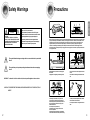
Precautions
Ensure that the AC power supply in your house complies with the identification sticker located on the back of your player. Install
your player horizontally, on a suitable base (furniture), with enough space around it for ventilation (3~4inches). Make sure the
ventilation slots are not covered. Do not stack anything on top of the player. Do not place the player on amplifiers or other
equipment which may become hot. Before moving the player, ensure the disc tray is empty. This player is designed for
continuous use. Switching off the DVD player to the stand-by mode does not disconnect the electrical supply. In order to
disconnect the player completely from the power supply, remove the main plug from the wall outlet, especially when left unused
for a long period of time.
Protect the player from moisture(i.e. vases) , and excess
heat(e.g.fireplace) or equipment creating strong magnetic or
electric fields (i.e.speakers...). Disconnect the power cable from
the AC supply if the player malfunctions. Your player is not
intended for industrial use.
Use of this product is for personal use only.
Condensation may occur if your player or disc have been
stored in cold temperatures.
If transporting the player during the winter, wait approximately
2 hours until the unit has reached room temperature before using.
During thunderstorms, disconnect AC main plug from
the wall outlet.
Voltage peaks due to lightning could damage the unit.
Do not expose the unit to direct sunlight or other heat
sources.
This could lead to overheating and malfunction of the
unit.
The battery used with this product contain chemicals
that are harmful to the environment.
Do not dispose of batteries in the general household
trash.
PREPARATION
VOLUME
Safety Warnings
This symbol indicates that dangerous voltage which can cause electric shock is present inside
this unit.
This symbol alerts you to important operating and maintenance instructions accompanying
the unit.
WARNING : To reduce the risk of fire or electric shock, do not expose this appliance to rain or moisture.
CAUTION : TO PREVENT ELECTRIC SHOCK, MATCH WIDE BLADE OF PLUG TO WIDE SLOT, FULLY
INSERT.
RISK OF ELECTRIC SHOCK.
DO NOT OPEN
CAUTION:
TO REDUCE THE RISK OF ELECTRIC
SHOCK, DO NOT REMOVE REAR COVER.
NO USER SERVICEABLE PARTS INSIDE.
REFER SERVICING TO QUALIFIED
SERVICE PERSONNEL.
CAUTION
Note to CATV system installer :
This reminder is provided to call the CATV system
installer’s attention to Section 820~40 of the NEC which
provides guidelines for proper grounding and, in
particular, specifies that the cable ground shall be
connected to the grounding system of the building, as
close to the point of cable entry as practical

54
READ INSTRUCTIONS
All the safety and operating instructions should be
read before the appliance is operated.
RETAIN INSTRUCTIONS
The safety and operating instructions should be
retained for future reference.
HEED WARNINGS
All warnings on the appliance and in the operating
instructions should be adhered to.
FOLLOW INSTRUCTIONS
All operating and use instructions should be
followed.
WATER AND MOISTURE
Do not use this video product near water-
for example, near a bathtub, wash bowl,
kitchen sink, or laundry tub, in a wet basement,
or near a swimming pool, and the like.
OVERLOADING
Do not overload wall outlets and extension cords as
this can result in the risk of fire
or electric shock.
VENTILATION
Slots and openings in the cabinet are provided
for ventilation and to ensure reliable operation of the
video product and to protect it from overheating
these openings must not be blocked or covered.
The openings should never be blocked
by placing the video product on a bed, sofa, rug, or
other similar surface. This video product
should never be placed near or over a radiator or
heat register.
This video product should not be placed
in a built-in installation such as a bookcase
or rack unless proper ventilation is provided
or the manufacturer's instructions have been
followed.
POWER CORD PROTECTION
Power-supply cords should be routed so that
they are not likely to be walked on or pinched
by items placed upon or against them paying
particular attention to cords at plugs,
convenience receptacles, and the point where
they exit from the appliance.
CLEANING
Unplug this video product from the wall outlet
before cleaning. Do not use liquid cleaners
or aerosol cleaners. Use a damp cloth for cleaning.
LIGHTNING
For added protection of this video product
receiver during a lightning storm, or when
it is left unattended and unused for long
periods of time, unplug it from the wall outlet
and disconnect the antenna or cable system.
This will prevent damage to the video product
due to lightning and power-line surges.
OBJECT AND LIQUID ENTRY
Never push objects of any kind into this
product through openings as they may touch
dangerous voltage points or short-out parts
that could result in a fire or electric shock.
Never spill liquid of any kind on the video
product.
ACCESSORIES
Do not place this video product on an unstable cart,
stand, tripod, bracket, or table.
The video product may fall, causing serious injury to
a child or adult, and serious damage
to the appliance.
Use only with a cart, stand, tripod, bracket,
or table recommended by the manufacturer,
or sold with the video product. Any mounting
of the appliance should follow the manufacturer's
instructions and should use a mounting accessory
recommended by the manufacturer.
CART
An appliance and cart combination should be moved
with care. Quick stops, excessive force, and uneven
surfaces may cause the appliance and cart
combination to overturn.
POWER SOURCES
This video product should be operated only from the
type of power source indicated
on the marking label. If you are not sure
of the type of supply to your home, consult your
appliance dealer or local power company.
For video products intended to be operated from
battery power, or other sources, refer
to the operating instructions.
POWER LINES
An outside antenna system should not be located in
the vicinity of overhead power lines or other electric
light or power circuits,
or where it can fall into such power lines
or circuits. When installing an outside antenna
system, extreme care should be taken to keep from
touching such power lines or circuits as contact with
them might be fatal.
POLARIZATION
This video product is equipped with a polarized
alternating current line plug (a plug having one blade
wider than the other.) This plug will fit into the power
outlet only one way.
This is a safety feature. If you are unable
to insert the plug fully into the outlet, try reversing
the
plug. If the plug should still fail to fit, contact your
electrician to replace your obsolete outlet. Do not
defeat the safety purpose of the polarized plug.
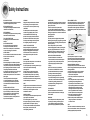
OUTDOOR ANTENNA GROUNDING
•
If an outside antenna is connected to the
antenna terminal, be sure the antenna system
is grounded so as to provide some protection
against voltage surges and built-up static
charges.
•
In the U.S.A section 810 of the National
Electrical Code, ANSI/NFPA No. 70-1984,
provides information with respect to proper
grounding of the mast and supporting
structure, grounding of the lead-in wire
to an antenna discharge unit, size of grounding
conductors, location of antenna discharge unit,
connection to grounding electrodes, and
requirements for the grounding electrode.
See the figure below.
ATTACHMENTS
Do not use attachments not recommended
by the video product manufacturer as they may
cause hazards.
SERVICING
•
Do not attempt to service this product yourself
as opening or removing covers may expose
you to dangerous voltage or other hazards.
•
Refer all servicing to qualified service personnel.
REPLACEMENT PARTS
When replacement parts are required, be sure the
service technician has used replacement parts
specified by the manufacturer or having the same
characteristics as the original part. Unauthorized
substitutions may result in fire, electric shock or other
hazards.
SAFETY CHECK
Upon completion of any service or repairs
to this video product, ask the service technician to
perform safety checks to determine that the video
product is in proper operating condition.
DAMAGE REQUIRING SERVICE
Unplug this video product from the wall outlet
and
refer servicing to qualified service personnel
under the
following conditions.
a.
When the power-supply cord or plug is damaged.
b. If liquid has been spilled, or objects have
fallen into the video product.
c. If the video product has been exposed to rain
or water
d.
If the video product does not operate normally
by following the operating instructions.
Adjust only those controls that are covered
by the operating instructions as an improper
adjustment of other controls may result
in damage and will often require extensive
work by a qualified technician to restore
the video product to its normal operation.
e. If the video product has been dropped
or the cabinet has been damaged.
f. When the video product exhibits a distinct
change in performance - this indicates
a need for service.
HEAT
This video unit should be situated away from heat
sources such as radiators, stoves, or other products
(including amplifiers) that produce heat.
ANTENNA
LEAD IN WIRE
ANTENNA
DISCHARGE UNIT
(NEC SECTION. 810-20)
GROUNDING CONDUCTORS
(NEC SECTION 810-21)
GROUND CLAMPS
POWER SERVICE GROUNDING
ELECTRODE SYSTEM
(NEC ART 250, PART H)
GROUND
CLAMP
ELECTRIC
SERVICE
EQUIPMENT
Safety Instructions
PREPARATION

76
Contents
PREPARATION
Safety Warnings ..............................................................................................................2
Precautions......................................................................................................................3
Safety Instructions ...........................................................................................................4
Features ..........................................................................................................................6
Description ......................................................................................................................8
CONNECTIONS
Connecting the Speakers ................................................................................................12
Connecting External Components ..................................................................................14
Connecting the FM and AM Antennas.............................................................................17
OPERATION
Before Using the AV Receiver .........................................................................................18
Selecting Digital/Analog Input .........................................................................................20
Setting the Speaker Mode ...............................................................................................22
Setting the Speaker Listening Distance .........................................................................24
Digital Input Setup ...........................................................................................................26
Setting DRC (Dynamic Range Compression) .................................................................27
Test Tone ........................................................................................................................28
Setting Speaker Level .....................................................................................................30
Dolby Pro Logic ll Mode..................................................................................................32
Dolby Pro Logic ll Effect .................................................................................................34
SFE Mode........................................................................................................................36
Stereo Mode ....................................................................................................................38
RADIO OPERATION
Listening to Radio ...........................................................................................................40
Presetting Radio Stations ...............................................................................................41
MISCELLANEOUS
Convenient Functions......................................................................................................42
Operating your TV with the Remote Control....................................................................44
Operating your VCR (DVD) with the Remote Control......................................................46
Before Calling for Service................................................................................................48
Specifications ..................................................................................................................50
WARRANTY ....................................................................................................................51
PREPARATION
Dolby Pro Logic II
Dolby Pro Logic II is a new form of multi-channel audio signal
decoding technology that improves upon existing Dolby Pro Logic.
DTS (Digital Theater Systems)
DTS play backs 5.1 channel sound with less compression than Dolby
Digital for richer sound.
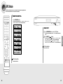
Features
Digital AV Receiver
This product is a pure digital AV receiver that performs digital signal processing to minimize
signal distortion and loss.
SFE(Sound Field Effect) Using 24bit Audio Digital Signal Processing
Provides more realistic surround sound with normal stereo audio sources.

98
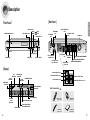
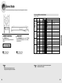
COOLING FAN
VCR/SAT VIDEO INPUT
JACK
AM ANTENNA
JACK
MONITOR VIDEO
OUTPUT JACK
FM ANTENNA
JACK
DVD OPTICAL DIGITAL
AUDIO INPUT JACK
CD COAXIAL DIGITAL
AUDIO INPUT JACK
VCR VIDEO OUTPUT
JACK
FRONT SPEAKER
TERMINALS
SUBWOOFER SPEAKER TERMINALS
[
Rear Panel
]
CD AUDIO INPUT JACKS
DVD AUDIO INPUT JACKS
VCR/SAT AUDIO INPUT JACKS
VCR AUDIO OUTPUT JACKS
SUBWOOFER OUTPUT JACKS 1, 2
PREPARATION
DVD VIDEO INPUT
JACK
CENTER SPEAKER TERMINALS
SURROUND SPEAKER TERMINALS
Description
[
Front Panel
]
[
Display
]
POWER button
HEADPHONE Jack
SELECT ( ) button
TUNING ( ) button
POWER STANDBY Indicator
SETUP button
FUNCTION button
SURROUND button
VOLUME CONTROL
INPUT MODE button
SPEAKER INDICATOR
DOLBY PRO
LOGIC II
INDICATOR
RADIO BROADCASTING
RECEIVING INDICATOR
RADIO STEREO INDICATOR
DIGITAL INDICATOR
RADIO FREQUENCY
INDICATOR
DTS
INDICATOR
LIVE SURROUND
INDICATOR
L.PCM
INDICATOR
DOLBY DIGITAL
INDICATOR
,
,
FRONT DISPLAY
DOLBY
INDICATOR
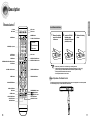
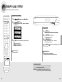
Accessories
√√
œœ
Remote Control
(AH59-01644U)
FM Antenna
(AH42-00017A)
User’s Manua
(AH68-01853R)
AM Antenna
(AH42-00019A)

1110
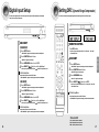
Insert Remote Batteries
The remote control can be used up to approximately 23 feet/7 meters in a straight line. It can also be operated
at a horizontal angle of up to 30° from the remote control sensor.
Range of Operation of the Remote Control
Remove the battery
cover in the direction
of the arrow.
1
Insert two 1.5V AAA
batteries, paying
attention to the correct
polarities (+ and –).
2
Replace the battery
cover.
3
Follow these precautions to avoid leaking or cracking batteries:
•
Place batteries in the remote control so they match the polarity:(+) to (+)and (–)to (–).
•
Use the correct type of batteries.Batteries that look similar may differ in voltage.
•
Always replace both batteries at the same time.
•
Do not expose batteries to heat or flame.
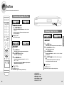
PREPARATION
Description
VOLUME CONTROL button
MUTE button
MENU button
POWER button
NUMBER(0~9) buttons
INFO button
SUBWOOFER button
SLEEP button
MO/ST button
TUNER button
SFE MODE button
STEREO button
SPK LEVEL button
SPK DISTANCE button
EXTERNAL DEVICE PLAYBACK button
CURSOR/ENTER button
TV button
AMP button
DVD button
VCR button
DIMMER button
TV VIDEO
,
FUNCTION button
CD button
VCR/SAT button
DVD button
DRC button
INPUT MODE DIGITAL button
INPUT MODE ANALOG button
TUNER MEMORY button
MODE button
TUNING MODE button
TUNER/CHANNEL button
SPK SELECT button
TEST TONE button
[
Remote Control
]
EFFECT button

1312
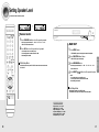
CONNECTIONS
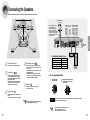
MAIN UNIT AV-R610
FRONT SPEAKER PS-AF610
CENTER SPEAKER PS-AC610
SURROUND SPEAKER PS-AR610
PASSIVE SUBWOOFER PS-AW610
SYSTEM MODEL NAME : HT-AS610
√ Connecting Speaker Wire
PASSIVE
SUBWOOFER
PS-AW610
ACTIVE SUBWOOFER
(not supplied)
FRONT (R)
PS-AF610
FRONT (L)
PS-AF610
SURROUND (R)
PS-AR610
SURROUND (L)
PS-AR610
MAIN UNIT
AV-R610
CENTER
PS-AC610
1
Press the tab of the
speaker connector.
2
Insert the black wire into the black(-)
terminal and the gray wire into the
red(+) terminal.
Connecting the Speakers
Before moving or installing the product, be sure to turn off the power and disconnect the power cord.
•
Place these speakers behind your listening position.
•
If there isn't enough room, place these speakers so they
face each other.
•
Place them about 60 to 90cm (2 to 3feet) above your ear,
facing slightly downward.
❈ Unlike the front and center speakers, the surround
speakers are used to handle mainly sound effects and
sound will not come from them all the time.
Surround Speakers
SL SR
•
Place these speakers in front of your listening
position, facing inwards (about 45°) toward you.
•
Place the speakers so that their tweeters will be at
the same height as your ear.
•
Align the front face of the front speakers with the
front face of the center speaker or place them
slightly in front of the center speaker.
Front Speakers
•
It is best to install it at the same height as the front
speakers.
•
You can also install it directly over or under the TV.
Center Speaker
•
Place AV Receiver on a dedicated stand or rack.
Position of AV Receiver
•
The position of the subwoofer is not so critical.
Place it anywhere you like.
Subwoofer
•
When you attach the speakers to a wall, make sure to
fasten them tightly so they do not fall off.
•
If more bass is desired, you can
connect an additional active
subwoofer (not supplied) to the
Subwoofer 1or 2 port. Since the
signal on the Subwoofer 1and 2 ports
is not stereo, you will hear the same
mono bass sound regardless of the
port you connect to.
•
Never touch speaker terminals while the power is on.
Doing so could result in electric shock.
•
Make sure the polarities (+ and -) are correct.
•
Keep the subwoofer speaker out of reach of children to prevent them from inserting their hands or objects
into the duct (hole) of the subwoofer speaker.
Caution

1514
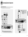
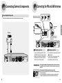
SAT
(Settop Box)
VCR
TV
•
The Analog Audio and Video In jacks of the main unit
can be used for SAT or VCR.You cannot connect both
devices at the same time.
•
If the external component has only one Audio Output
jack, connect it to either the right or left Audio Input
jack of the main unit.
•
Connect the audio cable's red plug to the red jack and
white cable to the white jack.
CONNECTIONS
Connecting External Components
DVD Player
or
Before moving or installing the product, be sure to turn off the power and disconnect the power cord.
Connecting Video Component
Video Projector
•
Disconnect the power plug from the outlet if you will not use this unit for a long period of time.
•
Even though the Digital Audio inputs are labelled DVD and CD, you can connect your DVD/CD player to either
the OPTICAL or COAXIAL digital audio input (as long as it matches the Digital audio output on your player).
or

1716
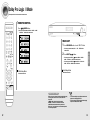
1. Connect the FM antenna supplied to the FM
75ΩCOAXIAL terminal as a temporary measure.
2. Slowly move the antenna wire around until you
find a location where reception is good, then
fasten it to a wall or other rigid surface.
1. Connect the AM loop antenna supplied to the AM
and terminals.
2. If reception is poor, connect an outdoor single
vinyl-covered wire to the AM terminal.
(Keep the AM loop antenna connected).
The cooling fan dissipates the heat generated inside the unit so that the unit can
be operated normally. The cooling fan is activated automatically to supply cool air
to the unit.
Please observe the following cautions for your safety.
•
Make sure the unit is well-ventilated. If the unit has poor ventilation, the temperature inside may
rise and cause damage to it.
•
Do not obstruct the cooling fan or ventilation holes. (If the cooling fan or ventilation holes are
covered with a newspaper or cloth, heat may build up inside the unit and fire may result.)
Connecting the FM and AM Antennas
FM antenna connection
If AM reception is poor, connect an
outdoor AM antenna(not supplied).
FM Antenna (supplied)
AM Loop Antenna
(supplied)
Snap the tabs on the loop into the
slots of the base to assemble the
AM loop antenna.
COOLING FAN
AM antenna connection
CONNECTIONS
Connecting External Components
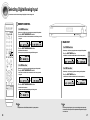
CD Player
Before moving or installing the product, be sure to turn off the power and disconnect the power cord.
Connecting Audio Component

1918
To Select a Function
REMOTE CONTROL
MAIN UNIT
Press FUNCTION button.
•
Each time you press the this button, FM ➝AM ➝DVD ➝ VCR/SAT ➝CD
will be selected in turn.
Method 1
Method 2
Press the FUNCTION button.
•
Each time you press the this button, FM ➝AM ➝DVD ➝ VCR/SAT ➝CD
will be selected in turn.
Press CD, VCR/SAT, DVD or TUNER button.
•
You can directly select CD, VCR/SAT, DVD or TUNER.
OPERATION
Functions of Dedicated Remote Control
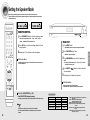
Connect the power plug to the outlet.
1
Press the POWER button of the main unit.
•
This unit will be turned on or set to Standby mode.
2
MAIN UNIT
REMOTE CONTROL
You can operate your AMP(this AV receiver), TV, DVD and VCR with this
remote control.
See pages 44-47 for more details.
Press the POWER button of the remote control.
•
This unit will be turned on or set to Standby mode.
Before Using the AV Receiver
Turning On/Off

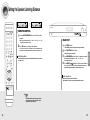
2120
MAIN UNIT
OPERATION
Selecting Digital/Analog Input
You can listen to sound in 2 Channel analog or Dolby Digital 5.1 Channel using this unit.
REMOTE CONTROL
For DVD Function
Follow steps 1-4 in DVD setup on page 26 before selecting the DVD Input Mode.
Press the INPUT MODE DIGITAL button.
•
DVD OPTICAL or COAXIAL will be selected based on the DVD setup you made
on page 26
Press the INPUT MODE ANALOG button.
•
DVD ANALOG will be selected.
•
DVD setup is not required before selecting the DVD Analog mode.
For CD Function
Follow steps 1-4 in CD setup on page 26 before selecting the CD Input Mode.
Press the INPUT MODE DIGITAL button.
•
CD OPTICAL or COAXIAL will be selected based on the CD setup you made
on page 26
Press the INPUT MODE ANALOG button.
•
CD ANALOG will be selected.
•
CD setup is not required before selecting the CD Analog mode.
For DVD Function
Follow steps 1-4 in DVD setup on page 26 before selecting the DVD Input Mode.
Press the INPUT MODE button.
•
DVD OPTICAL or COAXIAL and DVD ANALOG will be selected repetitively.
For CD Function
Follow steps 1-4 in CD setup on page 26 before selecting the CD Input Mode.
Press the INPUT MODE button.
•
CD OPTICAL or COAXIAL and CD ANALOG will be selected repetitively.
• You can enjoy Dolby Digital only if you connect the Digital Audio Output jack
of an external audio component to the Optical/Coaxial Digital Audio Input jack
on the main unit.
or
or
•
The product is set to “DVD:OPTICAL,CD:COAXIAL ” by factory default.

2322
Press SETUP button.
•
“SETUP MODE” appears on the display and enters into Setup Mode.
Press FUNCTION button 1 time.
•
“SPK SETUP” appears in the display.
Press SURROUND button to select the speaker you
want.
•
Each time you press this button, F.SPK ➝ C.SPK ➝S.SPK ➝SW SPK
➝CROVR will be selected in turn.
Press SELECT ( ) button to set the mode for the
selected speaker.
Repeat steps 3-4 to adjust each speaker.
To Exit Setup Mode
•
Wait for about 5 seconds or press SETUP button.
“SETUP MODE OFF” appears on the display and exits Setup Mode.
•
LARGE : Select when using large speakers. You can listen to full
range sound.
•
SMALL : Select this when using small speakers.
Bass below 100Hz will not be output.
•
NONE : Select this when you use no speaker.
•
YES(Subwoofer) : Select this when using the Subwoofer
Speaker.
•
NO(Subwoofer) : Select when not using the Subwoofer
Speaker.
•
CROVR: Select the crossover frequency for the best bass
response in your room.
Setting the Speaker
MAIN UNIT
1
2
4
5
3
,
OPERATION
Setting the Speaker Mode
Before moving or installing the product, be sure to turn off the power and disconnect the power cord.
Frequency response from the speaker will be adjusted according to your speaker configuration and whether certain
speakers are used or not.
Press SPK SELECT button to select the speaker you want.
•
Each time you press this button, F.SPK ➝ C.SPK ➝ S.SPK ➝SW SPK ➝
CROVR ➝SPK MODE OFF will be selected in turn.
Press …† button to set the mode (Large, Small etc.) for the
selected speaker.
Repeat steps 1-2 to set the mode for each speaker.
To Exit Setup Mode
•
Wait for about 5 seconds or press the SPK SELECT button of the remote control to
select SPK MODE OFF.
To turn the SUBWOOFER On or Off.
Press SUBWOOFER button on the remote.
•
Each time you press this button, SW SPK : YES, SW SPK : NO will be selected in turn.
√
1
2
3
REMOTE CONTROL
SPEAKER
F.SPK(Front)
C.SPK(Center)
S.SPK(Surround)
SW SPK(Subwoofer)
CROVR
(Crossover Frequency)
Possible Settings
LARGE,SMALL
LARGE,SMALL,NONE
LARGE,SMALL,NONE
YES
,NO
60,80,100,120,
150,180,200(Hz)
Default Setting
SMALL
SMALL
SMALL
YES
150Hz
•
If F.SPK is set to LARGE, you can select YES or NO for SW SPK.
•
If F. SPK is set to SMALL,SW SPK is automatically set to YES. NO cannot be
selected.

2524
Press SETUP button.
•
“SETUP MODE” appears on the display and enters into Setup Mode.
Press FUNCTION button 2 times.
•
“DIST SETUP” appears on the display.
Press SURROUND button to select the speaker you want.
•
Each time you press this button, F.L ➝ CEN ➝ F.R ➝ S.R ➝S.L ➝
S.W will be selected in turn.
Press SELECT( ) button to set the speaker distance.
•
For F.L, CEN, F.R, S.W, S.R, S.L Speaker, you can set the distance from the
speaker to listening position between 1~30 feet in intervals of 1 foot.
To Exit Setup Mode
•
Wait for about 5 seconds or press SETUP button.
“SETUP MODE OFF” appears on the display and Setup Mode is exited.
MAIN UNIT
1
2
4
3
,
OPERATION
Setting the Speaker Listening Distance
Press the SPK DISTANCE button to select the speaker
you want.
•
Each time you press this button, F.L ➝ CEN ➝ F.R ➝ S.R ➝ S.L ➝ S.W
➝ DIST OFF will be selected in turn.
Press …† button to set the speaker distance.
•
For F.L, CEN, F.R, S.W, S.R, S.L Speaker, you can set the distance from
the speaker to listening position between 1~30 feet in intervals of 1 foot.
To Exit Setup Mode
•
Wait for about 5 seconds or press the SPK DISTANCE button of remote control to
select DIST OFF.
√
•
If the listening position is beyond the range of speaker
distance setup when you place the speaker, set the
speaker distance to the maximum.
REMOTE CONTROL
1
2

2726
Digital Input Setup
You must set the digital input for a DVD or CD player to either Optical or Coaxial depending on which Digital
input you have your player connected to.
Press SETUP button.
•
“SETUP MODE” appears on the display and enters into Setup Mode.
Press FUNCTION button 3 times.
•
“DIGITAL IN” appears on the display.
Press SURROUND button to select DVD.
Press SELECT( ) button to set the digital input.
•
Each time you press this button, OPTICAL COAXIAL will be selected in turn.
MAIN UNIT
1
2
3
4
4
,
To Exit Setup Mode
•
Wait for about 5 seconds or press SETUP button.
“SETUP MODE OFF” appears on the display and the unit exits Setup Mode.
Press SETUP button.
•
“SETUP MODE” appears on the display and enters into Setup Mode.
Press FUNCTION button 3 times.
•
“DIGITAL IN” appears on the display.
Press SURROUND button to select CD.
Press SELECT( ) button to set the digital input.
•
Each time you press this button, OPTICAL COAXIAL will be selected in turn.
1
2
3
4
,
To Exit Setup Mode
•
Wait for about 5 seconds or press SETUP button.
“SETUP MODE OFF” appears on the display and the unit exits Setup Mode.
Setting DRC
(Dynamic Range Compression)
You can use this function to enjoy Dolby Digital sound when watching movies at low volume at night.
Press SETUP button.
•
“SETUP MODE” appears on the display and enters into Setup Mode.
Press FUNCTION button 4 times.
•
“DRC SETUP” appears on the display.
Press SURROUND button.
•
“DRC : STD” appears on the display .
Press SELECT( ) button to set DRC.
•
Each time you press this button, DRC : STD ➝ DRC : MAX ➝DRC : MIN
will be selected in turn.
To Exit Setup Mode
•
Wait for about 5 seconds or press SETUP button.
“SETUP MODE OFF” appears on the display and the unit exits Setup Mode.
√
•
STD : Sets DRC effect to standard.
•
MAX : Sets DRC effect to maximum.
•
MIN : Sets DRC effect to minimum.
Setting DRC
MAIN UNIT
1
2
3
Press DRC button.
•
Each time you press this button, DRC : STD ➝ DRC : MAX ➝ DRC : MIN
will be selected in turn.
REMOTE CONTROL
OPERATION
,
DVD SETUP
CD SETUP

2928
Test Tone
Use test tone to check the speaker connection status or level.
Press TEST TONE button.
•
Test signal will be automatically output as follows; F.L ➝CEN ➝F.R ➝S.R
➝S.L ➝S.W.
•
During test tone output, press …† button to adjust the speaker output level
from -10 to +10 dB by 1 step.
To Stop Test Tone
•
Press TEST TONE button again.
√
To Automatically Output Test Tone
REMOTE CONTROL
OPERATION
Press SETUP button.
•
“SETUP MODE” appears on the display and enters into Setup Mode.
Press FUNCTION button 5 times.
•
“TEST-T AUTO” appears in the display.
Press SURROUND button.
•
Test signal will be automatically output as follows; F.L ➝CEN ➝ F.R ➝
S.R ➝S.L ➝S.W .
•
During test signal output, press SELECT ( ) button to adjust the speaker
output level from -10 to +10 dB by 1 step.
√
MAIN UNIT
1
2
3
To Stop Test Tone
Press SETUP button 1 time.
•
“SETUP MODE OFF” appears on the display and test tone stops.
,
•
F.L (Front-Left) : -10 ~ +10dB
•
CEN (Center) : -10 ~ +10dB
•
F.R (Front-Right) : -10 ~ +10dB
•
S.R (Surround-Right) : -10 ~ +10dB
•
S.L (Surround-Left): -10 ~ +10dB
•
S.W (Subwoofer): -10 ~ +10dB
Test Tone Output
Press SETUP button.
•
“SETUP MODE” appears on the display and the unit enters into Setup Mode.
Press FUNCTION button 6 times.
•
“TEST-T MANU” appears in the display.
Press SURROUND button.
•
Each time you press this button, F.L ➝ CEN ➝ F.R ➝ S.R ➝S.L ➝ S.W will
be selected in turn.
Press SELECT( ) button to set the test tone as you
want.
•
You can adjust the speaker output level from -10 to +10dB by 1 step.
•
The sound gets quieter at -10dB and louder at +10dB.
√
To Manually Output Test Tone
MAIN UNIT
1
2
4
3
To Stop Test Tone
Press SETUP button 1 time.
•
“SETUP MODE OFF” appears on the display and test signal stops.
,

3130
•
F.L (Front-Left) : -10 ~ +10dB
•
CEN (Center) : -10 ~ +10dB
•
F.R (Front-Right) : -10 ~ +10dB
•
S.R (Surround-Right) : -10 ~ +10dB
•
S.L (Surround-Left): -10 ~ +10dB
•
S.W (Subwoofer): -10 ~ +10dB
To Exit Setup Mode
•
Wait for about 5 seconds or press SETUP button.
“SETUP MODE OFF” appears on the display and exits Setup Menu.
Press SETUP button.
•
“SETUP MODE” appears on the display and enters into Setup Mode.
Press FUNCTION button 8 times.
•
“LEVEL SETUP” appears on the display.
Press SURROUND button.
•
Each time you press this button, F.L ➝ CEN ➝ F.R ➝ S.R ➝S.L ➝ S.W
will be selected in turn.
Press SELECT( ) button to set the speaker level you
want.
•
You can adjust it from -10 to +10dB by 1 step.
•
The sound gets smaller at -10dB and louder at +10dB.
•
Default setting value is 00dB
Setting Speaker Level
MAIN UNIT
1
2
4
3
,
OPERATION
Setting Speaker Level
You can set the balance and level of speakers
Press SPK LEVEL button to select the speaker you want.
•
Each time you press this button, F.L ➝ CEN ➝ F.R ➝ S.R ➝S.L ➝ S.W ➝
SPK LVL OFF will be selected in turn.
Press …† button to set the speaker level you want.
•
You can adjust it from -10 to +10dB by 1 step.
•
The sound gets quieter at -10dB and louder at +10dB.
•
Default setting value is 00dB.
To Exit Setup Mode
•
Wait for about 5 seconds or press SPK LEVEL button on the remote control to select
SPK LVL OFF.
√
Remote Control
1
2

3332
•
MUSIC : Provides 5.1 Channel Surround sound to digital, analog
or existing stereo sources such as CD, TAPE, FM, TV and
Stereo VCR.
•
CINEMA : Adds realism to the movie soundtrack.
•
MATRIX : You will hear 5.1 Channel Surround sound.
•
GAME : Enhances the excitement of the game's sound.
•
PROLOGIC : You will experience a surround effect with just the
front left and right speakers.
Press SURROUND button to select “DPL ll” Mode.
•
Each time you press this button, DPL ll ➝ SFE ➝ STEREO will be
selected in turn.
Press SELECT( ) button.
•
Each time you press SELECT ( ) button, CINEMA ➝ MATRIX ➝
GAME ➝ PROLOGIC ➝MUSIC will be selected in turn.
•
Each time you press SELECT ( ) button, MUSIC ➝ PROLOGIC ➝
GAME ➝ MATRIX ➝CINEMA will be selected in turn.
Dolby Pro Logic ll Mode
To Exit Setup Mode
•
Wait for about 5 seconds.
MAIN UNIT
1
2
,
OPERATION
Dolby Pro Logic ll Mode
This mode provides 5.1 channel sound from 2 channel sources
Press MODE button.
•
Each time you press this button, CINEMA ➝ MATRIX ➝ GAME
➝ PROLOGIC ➝ MUSIC will be selected in turn.
To Exit Setup Mode
•
Wait for about 5 seconds.
REMOTE CONTROL
•
You cannot use Dolby Pro Logic ll Mode for multi channel
signals such as Dolby Digital and DTS.
•
Pro Logic works only for PCM audio signals with sampling
frequencies of 32KHz,44KHz or 48KHz.

3534
•
C-WIDTH : This sets the width of the center image. The higher the setting, the less
sound comes from the center speaker.
•
DIMENSION : Incrementally adjusts the sound field (DSP)from the front or rear.
•
PANORAMA : This mode extends the front stereo image to include the surround
speakers for an exciting "wraparound" effect with side wall imaging.
To Exit Setup Mode
•
Wait for about 5 seconds or press SETUP button.
“SETUP MODE OFF” appears on the display and exits Setup Mode.
Press SETUP button.
•
“SETUP MODE” appears on the display and enters into Setup Mode.
Press FUNCTION button 10 times.
•
“DPL ll MODE”appears on the display.
Press SURROUND button.
•
Each time you press this button, C-WIDTH ➝DIMENSION ➝
PANORAMA will be selected in turn.
Press SELECT( ) button to select Dolby Pro Logic ll
effect you want.
Dolby Pro Logic ll Effect
MAIN UNIT
1
2
4
3
,
OPERATION
Dolby Pro Logic ll Effect
This function works only in Dolby PRO LOGIC II MUSIC Mode.
Press MODE button to select ‘MUSIC’ Mode.
Press EFFECT button.
•
Each time you press this button, C-WIDTH ➝ DIMENSION ➝ PANORAMA
will be selected in turn.
Press …† button to select Dolby Pro Logic II effect you
want.
•
C-WIDTH: You can set from 0 to 7.
•
DIMENSION: You can set from -7 to +7.
•
PANORAMA: You can set it ON or OFF.
To Exit Setup Mode
•
Wait for about 5 seconds.
REMOTE CONTROL
1
2
3

3736
Press SURROUND button to select ‘SFE’ Mode.
•
Each time you press this button, DPL II ➝ SFE ➝ STEREO will be selected
in turn.
Press SELECT( ) button.
•
Each time you press Select ( ) button, HALL ➝THEATER ➝ARENA ➝
CLUB ➝DOME ➝STADIUM ➝CHURCH will be selected in turn
•
Each time you press Select ( ) button, CHURCH ➝STADIUM ➝
DOME ➝CLUB ➝ARENA ➝THEATER ➝HALL will be selected in turn.
To Exit Setup Mode
•
Wait for about 5 seconds.
MAIN UNIT
1
2
,
OPERATION
SFE Mode
The SFE (Sound Field Effect) function uses 7 different DSP sound field effects to digitally simulate
actual music environments such as concert halls or movie theaters.
Press SFE MODE button.
•
Each time you press this button, HALL ➝THEATER ➝ARENA ➝CLUB ➝
DOME ➝STADIUM ➝CHURCH will be selected in turn.
To Exit Setup Mode
•
Wait for about 5 seconds.
REMOTE CONTROL

3938
OPERATION
Stereo Mode
You can select this mode when listening to sound through the Front Left and Right speakers and subwoofer.
•
When PCM and Analog Stereo signals are input, the
left and right channels are played back in Stereo Mode.
Press STEREO button.
•
“STEREO” appears in the display and Stereo Mode is
selected.
Press SURROUND button to select ‘STEREO’.
•
Each time you press this button, DPL ll ➝ SFE ➝ STEREO
will be selected in turn.
To Exit Setup Mode
•
Wait for about 5 seconds.
To Exit Setup Mode
•
Wait for about 5 seconds.
REMOTE CONTROL MAIN UNIT
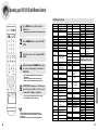
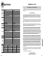
For Surround Mode and Input Signal
o = active, – = inactive
L/R : Front Speaker (Left/Right) C : Center Speaker SL/SR : Rear Speaker (Left/Right) SW : Subwoofer
•
Channel status displays are dependent on the speaker configuration.
•
SFE Mode works with 2ch signals.
Dolby D Surr. EX Dolby Digital 5.1
OOOO
DIGITAL L, C, R, SL, SR, SW
Dolby D (5.1ch) Dolby Digital 5.1
OOOO
DIGITAL L, C, R, SL, SR, SW
Dolby D (2ch) Pro Logic II
OOOO
DIGITAL L, C, R, SL, SR, SW
Dolby D (2ch Surr) Pro Logic II
OOOO
DIGITAL L, C, R, SL, SR, SW
L.PCM (Audio) Pro Logic II
OOOO
L.PCM L, C, R, SL, SR, SW
Analog Pro Logic II
OOOO
ANALOG L, C, R, SL, SR, SW
DTS-ES DTS 5.1
OOOO
DTS L, C, R, SL, SR, SW
DTS 96/24 DTS 5.1
OOOO
DTS L, C, R, SL, SR, SW
DTS (5.1) DTS 5.1
OOOO
DTS L, C, R, SL, SR, SW
L.PCM (Audio) Neo:6
OOO
-L.
PCM L, R
Dolby D (2ch) DD + SFE
OOOO
DIGITAL L, C, R, SL, SR, SW
Dolby D (2ch Surr) DD + SFE
OOOO
DIGITAL L, C, R, SL, SR, SW
L.PCM (Audio) SFE
OOOO
L.PCM L, C, R, SL, SR, SW
Analog SFE
OOOO
ANALOG L, C, R, SL, SR, SW
Dolby D (2ch) DD
O
---
DIGITAL L, R, SW
Dolby D (2ch Surr) DD
O
---
DIGITAL L, R, SW
L.PCM (Audio) Stereo
O
---
L.PCM L, R, SW
L.PCM 96KHz Stereo
O
---
L.PCM L, R, SW
Analog Stereo
O
---
ANALOG L, R, SW
Surround Mode
Input Signal
Decoding
Output Channel
L/R
C
SL
SR
Sub
Woofer
Display Information
Display Signal Format Channel Status
DOLBY
(MUSIC,
CINEMA,
MATRIX,
GAME,
PROLOGIC
)
DTS
STEREO
SFE
Page is loading ...
Page is loading ...
Page is loading ...
Page is loading ...
Page is loading ...
Page is loading ...
-
 1
1
-
 2
2
-
 3
3
-
 4
4
-
 5
5
-
 6
6
-
 7
7
-
 8
8
-
 9
9
-
 10
10
-
 11
11
-
 12
12
-
 13
13
-
 14
14
-
 15
15
-
 16
16
-
 17
17
-
 18
18
-
 19
19
-
 20
20
-
 21
21
-
 22
22
-
 23
23
-
 24
24
-
 25
25
-
 26
26


Samsung HT-AS610 User manual
- Type
- User manual
- This manual is also suitable for
Ask a question and I''ll find the answer in the document
Finding information in a document is now easier with AI
Related papers
Other documents
-
Zenith ZHD-311 Quick Setup Manual
-
Magnavox FW 375P User manual
-
Philips FW754P User manual
-
DK Digital AS-20-1 Owner's manual
-
-
Bosch SRU43A02SK/20 User manual
-
Sony ICF-M1000 User manual
-
Williams Sound SPK 024 Speaker User manual
-
Technicolor - Thomson Stereo Receiver DPL5000 User manual
-