
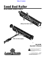
Cover photo may show optional equipment
not supplied with standard unit.
© Copyright 2008 Printed
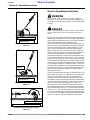
Read the Operator’s manual entirely. When
you see this symbol, the subsequent
instructions andwarnings are serious - follow
without exception. Your life and the lives of
others depend on it!
!
Table of Contents
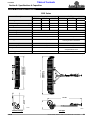
Model SBR48, SBR60 & SBR72
Seed Bed Roller
322-215M
Operator’s Manual
2/23/09
25762
25763
Without Pull Hitch Option
With Pull Hitch Option

Model SBR48, SBR60 & SBR72 Seed Bed Roller 322-215M
2/23/09
Land Pride
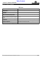
Table of Contents
© Copyright 2008 All rights Reserved
Land Pride provides this publication “as is” without warrantyof any kind, eitherexpressedor implied.While every precautionhas beentaken in the preparation ofthis manual, Land
Pride assumesnoresponsibilityfor errorsoromissions.Neitheris anyliabilityassumed fordamagesresultingfromthe use oftheinformation containedherein. Land Pride reserves
the rightto reviseandimprove itsproductsas it seesfit.This publicationdescribes thestateof this productatthe time ofitspublication,andmay notreflect the productinthefuture.
Land Pride is aregistered trademark.
All other brands and product names are trademarks or registered trademarks oftheir respective holders.
Printed in the United States of America.
Important Safety Information . . . . . . . . . . .1
Safety at All Times . . . . . . . . . . . . . . . . . . . . . . . . . 1
Look For The Safety Alert Symbol . . . . . . . . . . . . .1
Safety Labels . . . . . . . . . . . . . . . . . . . . . . . . . . . . . 4
Introduction . . . . . . . . . . . . . . . . . . . . . . . .5
Application . . . . . . . . . . . . . . . . . . . . . . . . . . . . . . . 5
Using This Manual . . . . . . . . . . . . . . . . . . . . . . . . . 5
Terminology . . . . . . . . . . . . . . . . . . . . . . . . . . . 5
Definitions . . . . . . . . . . . . . . . . . . . . . . . . . . . . . 5
Owner Assistance . . . . . . . . . . . . . . . . . . . . . . . . . 5
Serial Number Plate . . . . . . . . . . . . . . . . . . . . .5
Further Assistance . . . . . . . . . . . . . . . . . . . . . . 6
Section 1: Assembly & Set-up . . . . . . . . .7
Tractor Requirements . . . . . . . . . . . . . . . . . . . . . . 7
Three-Point Hook-up . . . . . . . . . . . . . . . . . . . . . 7
Pull Type Hook-Up . . . . . . . . . . . . . . . . . . . . . .7
Three Point Hitch Assembly . . . . . . . . . . . . . . . . . .7
Pull Type Hitch Assembly (Optional) . . . . . . . . . . .8
Roller Scraper Assembly . . . . . . . . . . . . . . . . . . . . 8
3-Point Hook-Up . . . . . . . . . . . . . . . . . . . . . . . . . . 9
Pull-type Hook-up . . . . . . . . . . . . . . . . . . . . . . . . 10
Clevis Hook-up . . . . . . . . . . . . . . . . . . . . . . . . 10
Ball Hook-up . . . . . . . . . . . . . . . . . . . . . . . . . . 10
Section 2: Adjustments . . . . . . . . . . . . . .11
Scraper Bar Adjustment . . . . . . . . . . . . . . . . . . . . 11
Ball Hitch Swivel Adjustment . . . . . . . . . . . . . . . . 11
Section 3: Operating Procedures . . . . . .12
Operating Check List . . . . . . . . . . . . . . . . . . . . . .12
Transporting . . . . . . . . . . . . . . . . . . . . . . . . . . . . .12
Operating Instructions . . . . . . . . . . . . . . . . . . . . .13
Unhooking the Seed Bed Roller . . . . . . . . . . . . . .14
Storage Instructions . . . . . . . . . . . . . . . . . . . . . . .14
General Operating Instructions . . . . . . . . . . . . . .15
Section 4: Maintenance & Lubrication . .16
Maintenance . . . . . . . . . . . . . . . . . . . . . . . . . . . .16
Lubrication . . . . . . . . . . . . . . . . . . . . . . . . . . . . . .16
Roller Flange Bearings . . . . . . . . . . . . . . . . . .16
Wheel Bearings . . . . . . . . . . . . . . . . . . . . . . . .16
Section 5: Additional Equipment . . . . . . .17
Additional Seeding Equipment . . . . . . . . . . . . . . .17
Disc Harrow . . . . . . . . . . . . . . . . . . . . . . . . . . .17
Electric Spin Spreader . . . . . . . . . . . . . . . . . . .17
Drag Harrow . . . . . . . . . . . . . . . . . . . . . . . . . . . . .17
Complete One Pass Seeding Application . . . .18
Section 6: Specifications & Capacities .19
Section 7: Features and Benefits . . . . . .20
Section 8: Appendix . . . . . . . . . . . . . . . .21
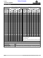
Torque Values Chart For Common Bolt Size . . . .21
Notes . . . . . . . . . . . . . . . . . . . . . . . . . . . . . . . . . .22
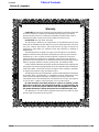
Warranty . . . . . . . . . . . . . . . . . . . . . . . . . . . . . . .23
Table of Contents

1
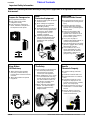
Important Safety Information
2/23/09
Model SBR48, SBR60 & SBR72 Seed Bed Roller 322-215M
Land Pride
Table of Contents
Important Safety Information
▲
These are common practices that may or may not be applicable to the products described in
this manual.
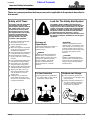
Safety at All Times
Thoroughly read and understand
the instructions given in this
manual before operation. Refer to
the “Safety Label” section, read
all instructions noted on them.
Do not allow anyone to operate
this equipment who has not fully
read and comprehended this
manual and who has not been
properly trained in the safe
operation of the equipment.
▲ Operator should be familiar with
all functions of the unit.
▲ Operate implement from the
driver’s seat only.
▲ Make sure all guards and shields
are in place and secured before
operating the implement.
▲ Do not leave tractor or implement
unattended with engine running.
▲ Dismounting from a moving
tractor could cause serious injury
or death.
▲ Do not stand between the tractor
and implement during hitching.
▲ Keep hands, feet, and clothing
away from power-driven parts.
▲ Wear snug fitting clothing to avoid
entanglement with moving parts.
▲ Watch out for wires, trees, etc.,
when raising implement. Make
sure all persons are clear of
working area.
▲ Turning tractor too tight may
cause implement to ride up on
wheels. This could result in injury
or equipment damage.
!
Look For The Safety Alert Symbol
The SAFETY ALERT SYMBOL indicates there is a
potential hazard to personal safety involved and extra
safety precaution must be taken. When you see this
symbol, be alert and carefully read the message that
follows it. In addition to design and configuration of
equipment, hazard control and accident prevention
are dependent upon the awareness, concern,
prudence and proper training of personnel involved in
the operation, transport, maintenance and storage of
equipment.
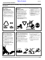
Be Aware of
Signal Words
A Signal word designates a degree or
level of hazard seriousness. The
signal words are:
Indicates an imminently hazardous
situation which, if not avoided, will
result in death or serious injury. This
signal word is limited to the most
extreme situations, typically for
machine components that, for
functional purposes, cannot be
guarded.
!
DANGER
Indicates a potentially hazardous
situation which, if not avoided, could
result in death or serious injury, and
includes hazards that are exposed
when guards areremoved. It may also
be used to alert against unsafe
practices.
Indicates a potentially hazardous
situation which, if not avoided, may
result in minor or moderate injury. It
may also be used to alert against
unsafe practices.
!
WARNING
!
CAUTION
For Your Protection
▲ Thoroughly read and understand
the “SafetyLabel”section, read all
instructions noted on them.
Shutdown and Storage
▲ Lower machine to ground, put
tractor in park, turn off engine, and
remove the key.
▲ Detach and store implements in a
area where children normally do
not play. Secure implement by
using blocks and supports.
OFF
REMO
VE

2
Important Safety Information
Model SBR48, SBR60 & SBR72 Seed Bed Roller 322-215M
2/23/09
Land Pride
Table of Contents
These are common practices that may or may not be applicable to the products described in
this manual.
Transport
Machinery Safely
▲ Comply with state and local laws.
▲ Maximum transport speed for
implement is 20 mph. DO NOT
EXCEED. Never travel at a speed
which does not allow adequate
control of steering and stopping.
Some rough terrain require a
slower speed.
▲ Sudden braking can cause a
towed load to swerve and upset.
Reduce speed if towed load is not
equipped with brakes.
▲ Use the following maximum
speed - tow load weight ratios as
a guideline:
▲ 20 mph when weight is less than
or equal to the weight of tractor.
▲ 10 mph when weight is double
the weight of tractor.
▲ IMPORTANT: Do not tow a load
that is more than double the
weight of tractor.
Use Safety
Lights and Devices
▲ Slow moving tractors, self-
propelled equipment, and towed
implements can create a hazard
whendrivenonpublicroads. They
are difficult to see, especially at
night.
▲ Flashing warning lights and turn
signals are recommended
whenever driving on public roads.
Practice Safe Maintenance
▲ Understand procedure before doing
work. Use proper tools and
equipment, refer to Operator’s
Manual for additional information.
▲ Work in a clean dry area.
▲ Lower the implement to the ground,
put tractor in park, turn off engine,
and remove key before performing
maintenance.
▲ Allow implement to cool completely.
▲ Do not grease or oil implement
while it is in operation.
▲ Inspect all parts. Make sure parts
are in good condition & installed
properly.
▲ Remove buildup of grease, oil or
debris.
▲ Remove all tools and unused
parts from implement before
operation.
Use A Safety Chain
▲ A safety chain will help control
drawn machinery should it
separate from the tractor
drawbar.
▲ Use a chain with the strength
rating equal to or greater than
the gross weight of the towed
machinery.
▲ Attach the chain to the tractor
drawbar support or other
specified anchor location. Allow
only enough slack in the chain
to permit turning.
▲ Do not use safety chain for
towing.

3
Important Safety Information
2/23/09
Model SBR48, SBR60 & SBR72 Seed Bed Roller 322-215M
Land Pride
Table of Contents
These are common practices that may or may not be applicable to the products described in
this manual.
Prepare for Emergencies
▲ Be prepared if a fire starts.
▲ Keep a first aid kit and fire
extinguisher handy.
▲ Keep emergency numbers for
doctor, ambulance, hospital and
fire department near phone.
911
Wear
Protective Equipment
▲ Protectiveclothing and equipment
should be worn.
▲ Wear clothing and equipment
appropriate for the job. Avoid
loose fitting clothing.
▲ Prolonged exposure to loud noise
can cause hearing impairment or
hearing loss. Wear suitable
hearing protection such as
earmuffs or earplugs.
▲ Operating equipment safely
requires the full attention of the
operator. Avoid wearing radio
headphones while operating
machinery.
Avoid High
Pressure Fluids Hazard
▲ Escaping fluid underpressurecan
penetratetheskincausingserious
injury.
▲ Avoid the hazard by relieving
pressure before disconnecting
hydraulic lines or performing work
on the system.
▲ Make sure all hydraulic fluid
connections are tight and all
hydraulic hoses and lines are in
good condition before applying
pressure to the system.
▲ Use a piece of paper or
cardboard, NOT BODY PARTS, to
check for suspected leaks.
▲ Wear protective gloves and safety
glasses or goggles when working
with hydraulic systems.
▲ If an accident occurs, see a
doctor immediately. Any fluid
injected into the skin must be
treated within a few hours or
gangrene may result.
Keep Riders
Off Machinery
▲ Riders obstruct the operator’s
view, they could be struck by
foreign objects or thrown from the
machine.
▲ Never allow children to operate
equipment.
Handle
Chemicals Properly
▲ Protective clothing should be
worn.
▲ Handle all chemicals with care.
▲ Follow instructions on container
label.
▲ Agricultural chemicals can be
dangerous. Improper use can
seriously injure persons, animals,
plants, soil, and property.
▲ Inhaling smoke from any type of
chemical fire is a serious health
hazard.
▲ Store or dispose of unused
chemicals as specified by the
chemical manufacturer.
Tire Safety
▲ Tire changing can be dangerous
and should be preformed by
trained personnel using the
correct tools and equipment.
▲ When inflating tires, use a clip-on
chuck and extension hose long
enough to allow you to stand to
one side and NOT in front of or
over the tire assembly. Use a
safety cage if available.
▲ When removing and installing
wheels, use wheel handling
equipment adequate for the
weight involved.

4
Important Safety Information
Model SBR48, SBR60 & SBR72 Seed Bed Roller 322-215M
2/23/09
Land Pride
Table of Contents
848-148C
Negative Hitch Weight
Located below and above the tongue.
25762
Below Tongue
Above Tongue
Safety Labels
Your Seed Bed Roller comes equipped with all safety
labels in place. They were designed to help you safely
operate your implement. Read and follow their
directions.
1. Keep all safety labels clean and legible.
2. Replace all damaged or missing labels. To order new
labels go to your nearest Land Pride dealer or visit our
dealer locator at landpride.com.
3. Some new equipment installed during repair requires
safety labels to be affixed to the replaced component as
specified by Land Pride. When ordering new components
make sure the correct safety labels are included in the
request.
4. Refer to this section for proper label placement.
To install new labels:
a. Clean the area the label is to be placed.
b. Spray soapy water on the surface where the label is to
be placed.
c. Peel backing from label. Press firmly onto the surface.
d. Squeeze out air bubbles with the edge of a credit card.

5
Introduction
2/23/09
Model SBR48, SBR60 & SBR72 Seed Bed Roller 322-215M
Land Pride
Table of Contents
Terminology
“Right” or “Left” as used in this manual is determined by
facing the directionthe machinewill operate while in use
unless otherwise stated.
Definitions
Owner Assistance
The Warranty Registration card should be filled out by
the dealer at the time of purchase. This information is
necessary to provide you with quality customer service.
If customer service or repairparts are required contact a
LandPridedealer. Adealerhas trainedpersonnel,repair
parts and equipment needed to service the Seed Bed
Roller.
The parts on your Seed Bed Roller have been specially
designedandshouldonlybereplacedwithgenuineLand
Pride parts. Therefore should your Seed Bed Roller
require replacement parts go to your Land Pride Dealer.
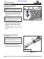
Serial Number Plate
For prompt service always use the serial number and
modelnumber when ordering partsfrom your Land Pride
dealer.Besuretoincludeyourserialandmodel numbers
incorrespondence also.Referto Figure1 forthe location
of your serial number plate.
Serial Number Plate Location
Figure 1
NOTE: A special point of information that the
operator must be aware of before continuing.
IMPORTANT: A special point of information related
to its preceding topic. Land Pride’s intention is that
this information should be read and noted before
continuing.
25763
Introduction
Land Pride welcomes you to the growing family of new
product owners. This Seed Bed Roller has been
designed with care and built by skilled workers using
quality materials. Proper assembly, maintenance and
safe operating practices will help you get years of
satisfactory use from the machine.
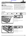
Application
The Land Pride SBR48, SBR60 and SBR72 Three-point
hitch or Pull-Type Seed Bed Rollers have uses and
applications in landscaping, sports field maintenance,
pasture maintenance, professional turf care, general
seeding and overseeding applications around home
sites, construction sites, horsepaddocks, nurseries, sod
farms, and small farm or ranch operations. These Seed
Bed Rollers will break up smaller clumps and dirt clods,
whilepressing applied seed into firm contactwith the soil
profile for greatly improved germination rates. The
notched profile of the rollers also develops a pattern of
uniformlyspaced mini-furrows thattend tohold seed and
fertilizer in place. These small furrows also retain
essential moisture, and resist erosion from the wind and
the runoff from applied irrigation or rain.
The Seed Bed Roller also can also serve as the roller
packer attachment of Land Pride’s complimented
Seeder/Overseedersystem.Thissystemiscomprisedof
a Land Pride Disc Harrow with a rear mounted Spin
Spreader and special hitch kit, a trailing 6’ x 4’ DRG06
Drag Harrow, and trailing Pull-type SBR72 Seed Bed
Roller. This componentized Seeder/Overseeder system
provides for one-pass ground cultivation and seed to soil
integration for applications on previously tilled soil,
existingpasture ground, large grassy areas, reclamation
sites, or wild game food plots.
See“Section 6: Specifications & Capacities” on page
19 and “Section 7: Features and Benefits” on page20
for additional information and performance enhancing
options.
Using This Manual
•
This Operator’s Manual is designed to help familiarize
you with safety, assembly, operation, adjustments,
troubleshooting, and maintenance. Read this manual
and follow the recommendations to help ensure safe
and efficient operation.
• The information contained within this manual was
current at the timeof printing.Some partsmay change
slightly to assure you of the best performance.
• To order a new Operator’s or Parts Manual contact
your authorized dealer. Manuals can also be
downloaded, free-of-charge from our website at
www.landpride.com.

6
Introduction
Model SBR48, SBR60 & SBR72 Seed Bed Roller 322-215M
2/23/09
Land Pride
Table of Contents
Further Assistance
Yourdealerwantsyou tobesatisfiedwith yournewSeed
Bed Roller. If for any reason you do not understand any
part of this manual or are not satisfied with the service
received, the following actions are suggested:
1. Discuss the matter with your dealership service
manager making sure he is aware of any problems
youmay have andthat hehas had the opportunity to
assist you.
2. If you are still not satisfied, seek out the owner or
general manager of the dealership, explain the
problem and request assistance.
3. For further assistance write to:
Land Pride Service Department
1525 East North Street
P.O. Box 5060
Salina, Ks. 67402-5060
E-mail address
lpser[email protected]

7
Section 1: Assembly & Set-up
2/23/09
Model SBR48, SBR60 & SBR72 Seed Bed Roller 322-215M
Land Pride
Table of Contents
Tractor Requirements
The tractor horsepower and weight must be capable of
controlling the Seed Bed Roller under all operating
conditions. Smaller horsepower and lighter weight
tractors must not be used.
Three-Point Hook-up
A Category I hitch with 7/8” dia. holes in the lower hitch
links and 3/4” dia. hole in the top link is required. The
lower 3-point arms must be stabilized to prevent side-to-
side movement. Most tractors have sway blocks or
adjustable chains for this purpose. A Category I Land
Pride Quick Hitch can be used with the implement.
Horsepower requirements. . . . . . . . . . . . . . .18 - 50 hp.
Minimum tractor weight . . . . . . . . . . . . . . . . . . 700 lbs.
Pull Type Hook-Up
The Pull Type Model is set-up with a 2" ball hitch and a
clevis type hitch.
Pull-type HP. . . . . . . . . . . . . . . . . . . . . . . . . .18 - 50 hp.
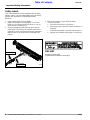
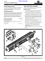
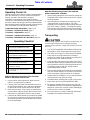
Three Point Hitch Assembly
Refer to “Torque Values Chart For Common Bolt Size”
on page 21 when tightening hardware.
Refer to Figure 1-1:
1. Chock front and back of rollers to prevent unit from
shifting while assembling the hitch assembly.
2. Attach support stand (#3) to clevis plate with 5/8"
wire snap lock pin (#10). Make certain notch “A” is
located against the square tubing corner as shown.
3. Attachbottom ofhitch frame(#4) to clevisplateswith
two 5/8"-11 x 1 1/2" GR5 round head square neck
bolts (#6) and 5/8" hex flange lock nuts (#7). Draw
nuts up snug, do not tighten.
4. Attach upper two holes inhitch frame to clevis plates
with hitch pins (#1) and linch pins (#9)
5. Install 3/4"-10 x 3 1/2" GR5 hex head cap screw
(#5A) with1 1/4" x 2" spacer (#2) and 3/4" hexflange
lock nut (#7). Tighten nut to the correct torque.
6. Install 3/4"-10 x 3 1/2" GR5 hex head cap
screw (#5B) and 3/4" hex flange lock nut (#8).
Draw nut up snug.
7. Tighten 5/8" hex flange lock nuts (#7) to the corrrect
torque.
Section 1: Assembly & Set-up
Three point Hitch Assembly
Figure 1-1
25773

8
Section 1: Assembly & Set-up
Model SBR48, SBR60 & SBR72 Seed Bed Roller 322-215M
2/23/09
Land Pride
Table of Contents
c. Attach back of tongue with two 3/8"-16 x 1" GR5
cap screws (#8) and 3/8" flange lock nuts (#15).
7. Tighten flange lock nuts (#14, #15 & #16) to the
correct torques.
8. Remove wire snap lock pin (#1B). Reorient ball
hitch (#6) and clevis hitch (#7) with preferred hitch
facing forwardand then reattachhitch totongue (#5)
with wire snap lock pins (#1A & 1B).
9. Attachsupportstand(#3)towiresnaplockpin(#1A).
When not in use,rotate standup and secure in place
with second wire snap lock pin (#1B).
10. If clevis hitch (#7) is facing forward, insert 3/4" hitch
pin (#12) and secure with hair pin cotter (#13). If ball
hitch (#6) is facing forward, store hitch pin and hair
pin cotter in a safe location of your choosing.
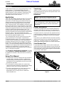
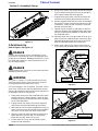
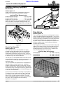
Roller Scraper Assembly
Refer to “Torque Values Chart For Common Bolt Size”
on page 21 when tightening hardware.
Refer to Figure 1-4 on page 9:
1. Attach roller scraper assembly to the Seed Bed
Roller frame with 3/8"-16 x 1" GR5 round head
square neck bolts (#2) and hex flange lock nuts (#3).
2. Tighten nuts to the correct torque.
3. Some adjustment to the scraper teeth can be made
bylooseningthenutsonscraper(#1).Retightennuts
after adjustment has been made. See “Scraper Bar
Adjustment” on page 11 for detailed instructions.
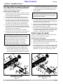
NOTE: See Figure 1-3. Ball hitch (#6) and clevis
hitch (#7) can be installed with either hitch facing
forward. Determine which hitch you intend to use
and face that hitch forward.
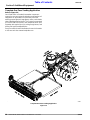
Pull Type Hitch Assembly
With Drawbar 13" & Higher
Figure 1-2
Pull Type Hitch Assembly
With Drawbar under 13" High
Figure 1-3
25774
26518
Pull Type Hitch Assembly (Optional)
Refer to “Torque Values Chart For Common Bolt Size”
on page 21 when tightening hardware.
Refer to Figure 1-2 & Figure 1-3:
1. Chock front and back of rollers to prevent unit from
shifting. Support 2" square tube frame up so that the
top of the clevis plates are level.
2. Remove support stand (#3) and wire snap lock
pin (#1A) from the clevis plates (shipping location).
3. The front two holes in hitch frame (#4) should be
shipped from the factory attached to the front holes
in the clevis plates with hitch pins (#17) and linch
pins (#11). If not, make this pin connection now.
4. Rotate hitch frame (#4) down to align rear holes in
hitchframewithholesatthe backoftheclevisplates.
Insert 5/8"-11 x 1 1/2" GR5 carriage bolts (#10) and
secure with 5/8" hex flange lock
nuts (#16). Draw nuts up snug, do not tighten.
5. Remove3/4"hexcapscrews(#9),2"spacer(#2)and
and 3/8" cap screws (#8) from hitch frame (#4).
6. Attach tongue (#5) to 3-point hitch (#4) as follows:
a. Remove bolts (#8) from back of tongue (#5).
b. Attach middle of tongue to hitch (#2) with two
3/4"-10 x 3 1/2" GR5 cap screws (#9), one 2" lg.
spacer (#2) and two 3/4" flange lock nuts (#14).
IMPORTANT: The tongue (#5) should be as near
level as possible when pulling the roller over soil.
Before proceeding, determine which hitch assembly
below to use that will mount the tongue near level.
• Use hitch assembly in Figure 1-2 to mount
tongue (#5) if tractor drawbar is lower than 13"
• Use hitch assembly in Figure 1-3 to mount
tongue (#5) if tractor drawbar is 13" or higher.

9
Section 1: Assembly & Set-up
2/23/09
Model SBR48, SBR60 & SBR72 Seed Bed Roller 322-215M
Land Pride
Table of Contents
Roller Scraper Assembly
Figure 1-4
3-Point Hook-Up
Refer to Figure 1-5 & Figure 1-6:
!
DANGER
Crushing Hazard between tractor and implement. Do not
allow anyone to stand between tractor and implement while
backing-upto an implement. Do not operate hydraulic3-point
lift controls while someone is directly behind the tractor or
near the Seed Bed Roller.
!
DANGER
Engage parking brake, shut off tractor and remove key before
dismounting from the tractor.
!
WARNING
See Figure 3-5 on page 15. Chock front and back of roller
when using support stand to prevent unit from rolling and
causing property damage and/or bodily injury.
A 3-Point Category I hitch is required. The lower 3-Point
arms of the 3-Point hitch must be stabilized to prevent
side-to-side movement. Most tractors have sway blocks
or adjustable chains for this purpose.
1. Slowly back tractor up to the Seed Bed Roller while
using the tractor’s 3-point hydraulic control to align
the lower lift arm hitch holes with the clevis lug holes
on the Seed Bed Roller.
2. Engage tractor park brake, shut tractor engine off
and remove key before dismounting from tractor.
3. With lower lift arm hitch holes aligned with clevis lug
holes, insert hitch pins (#1) through clevis and lower
arm holes. Secure hitch pins with linchpins (#6).
4. Align top center link hitch hole with the upper hitch
holes and insert 3/4" bolt (#4). Secure bolt with
flange lock nut (#5). Draw nut up snug.
5. Ensure lower hitch arms are blocked to prevent
excessive side movement.
2576
4
6. Returnto the tractor, start engine andslowly operate
3-point controls to lift lower arms up just enough to
raise support stand (#3) off the ground.
7. Engage tractor park brake, shut tractor engine off
and remove key before dismounting from tractor.
8. Remove support stand (#3),turn it overand reattach
it asshown in Figure 1-6 with wire snap lockpin (#7).
(Remember: Small notches in stand are mounted
towards the frame tube.)
9. Operate 3-point controls up and down to check for
clearance between the Seed Bed Roller and tractor.
Move or remove tractor drawbar if it interferes with
the Seed Bed Roller.
10. Manually adjust one of the two Lower lift arms up or
down to level the Seed Bed Roller from left to right.
Manually adjust the length of the top center link to
level the Seed Bed Roller from front to rear.
11. When using a Quick Hitch, attach center hook to
1 1/4" spacer (#2) and lowerhooks to hitch pins (#1).
Tractor 3-Point Hitch
Figure 1-5
Seed Bed Roller Hook-Up
Figure 1-6
23998
Top Center Link
Hitch Hole
Lower Lift Arm
Hitch Holes
PTO Shaft
25781
Lower Lift Arm Hole
Alignment Positions
Top Center Link Hole
Alignment Position

10
Section 1: Assembly & Set-up
Model SBR48, SBR60 & SBR72 Seed Bed Roller 322-215M
2/23/09
Land Pride
Table of Contents
Pull-type Hook-up
!
DANGER
Crushing Hazard between tractor and implement. Do not
allow anyone to stand between the tractor and implement
while backing-up to an implement.
!
DANGER
Engage parking brake, shut off tractor and remove key before
dismounting from the tractor.
!
WARNING
The Seed Bed Roller hitch has negative weight.
!
WARNING
See Figure 3-5 on page 15. Chock front and back of roller
when using support stand to prevent unit from rolling and
causing property damage and/or bodily injury.
Clevis Hook-up (Tractor drawbar height under 13")
Figure 1-7
Clevis Hook-up (Tractor drawbar height 13" and higher)
Figure 1-8
25799
25783
Clevis Hook-up
Refer to Figure 1-7 & Figure 1-8:
1. Backmachine upto the SeedBed Roller untilhole in
drawbar hitch is aligned with holes inthe clevis hitch.
2. Dismount machine properly and insert hitch pin (#3)
through hitch clevis holes and drawbar hitch hole.
Install hair pin cotter (#4).
3. Without removing wire snap lock pins (#5A & #5B):
• Unhook wire retainers for both pins (#5A & #5B).
• Rotate bottom of support stand (#1) back until hole
“A” is in alignment with wire snap lock pin (#5B).
• Push support stand onto both wire snap lock pins
and re-hook wire retainers.
Ball Hook-up
Refer to Figure 1-9:
1. Attach customer supplied2" ball (#8) to themachine
pulling the Seed Bed Roller. Tighten nut supplied
with the ball tocorrect torque. 2" Ballwith 3/4"shank
(P/N 890-975C) can be purchased from Land Pride.
2. Back machine up to the Seed Bed Roller until the 2"
ball is in alignment with ball socket in hitch (#2).
Ball Hook-up (Drawbar height 13" and higher)
Figure 1-9
3. Remove retaining pin (#3), pull up on lock latch
trigger (#6) and then pull up on release handle (#4).
4. Withhandle(#4)up,lowerhitch(#2) over2"ball(#8).
5. Make sure hitch (#2) is fully on ball (#8) and then
pushhandle(#4)downuntillocklatch(#6)issecured
in notch (#7).
6. Insert wire retaining pin (#3) in hole “A” and secure
pin in place with its wire retainer.
7. Without removing the two front wire snap lock
pins (#5A & #5B):
• Unhook wire retainers for both pins (#5A & #5B).
• Rotate bottom of support stand (#1) back until hole
“A” is in alignment with wire snap lock pin (#5B).
• Push support stand onto both wire snap lock pins
and re-hook wire retainers.
25776

11
Section 2: Adjustments
2/23/09
Model SBR48, SBR60 & SBR72 Seed Bed Roller 322-215M
Land Pride
Table of Contents
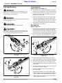
Scraper Bar Adjustment
Refer to Figure 2-1:
1. Slightly loosen hex nuts (#3) on both ends of the
scraper bar (#1). Nuts should be loose enough to
allowscraper bar movementbut tight enough to hold
the scraper bar in place until nuts have been
retightened.
2. Adjust scraper bar (#1) left or right to center scraper
teeth (#A) in the roller flutes and up or down until the
teeth just clear the bottom of the roller flutes. Some
light tapping with a hammer against a properly
placed block of wood may be required to move the
scraper bar.
3. Tighten 3/8"-16 nuts (#3) to the correct torque. Refer
to “Torque Values Chart For Common Bolt Size” on
page 21.
Ball Hitch Swivel Adjustment
Refer to Figure 2-2:
1. Hold plate (#1) from turning and tighten hex flange
nut (#3) until plate (#1) is against plate (#2).
2. Rotateballhitchaboutplate (#2)byhand.Ifballhitch
will not rotate, back nut (#3) off until it will rotate.
IMPORTANT: Scraper bar must be adjusted with
rear roller resting on the ground to ensure roller
rings are in their upper most position.
IMPORTANT: Tapping with a hammer may be
required to move scraper bar (#1). When doing so,
be sure to place a block of wood in the area to be
tapped. Tap hammer against the wood and not the
scraper bar to help protect the finish.
IMPORTANT: Hex flange lock nut (#3) should be
adjusted tight enough so that the two mating plates
(#1 & #2) make contact but looseenough so that the
plates can rotate against each other.
A 16" long socket extension and 1 1/8" hex socket
will be required to reach the 3/4" hex flange nut (#3).
Scraper Adjustment
Figure 2-1
Ball Hitch Swivel Adjustment
Figure 2-2
25784
2578
5
Insert Socket Extension
In This Opening
Section 2: Adjustments

12
Section 3: Operating Procedures
Model SBR48, SBR60 & SBR72 Seed Bed Roller 322-215M
2/23/09
Land Pride
Table of Contents
Operating Check List
Hazard control and accident prevention are dependent
upon the awareness, concern, prudence and proper
training involved in the operation, transport,
maintenance and storage of the Seed Bed Roller.
Therefore, it is absolutely essential that no oneoperates
the roller without first having read, fully understood and
becometotallyfamiliarwiththeOperator’sManual.Make
sure the operator has paid particular attention to:
• Important Safety Information, pages 1 to 4
• Section 1: Assembly & Set-up, page 7
• Section 2: Adjustments, page 11
• Section 3: Operating Procedures, page 12
• Section 4: Maintenance & Lubrication, page 16
Make the following inspections if the Seed Bed
Roller is attached to a 3-Point lift:
1. Inspect tractor safety equipment. Make sure the
tractor is in good working condition.
2. Carefully raise and lower the implement to ensure
that the tractor drawbar, tires, and other equipment
on the tractor do not contact the frame and roller.
3. Make sure the lower 3-Point arms are stabilized to
prevent side-to-side movement. Most tractors have
sway blocks or adjustable chains for this purpose.
4. Check tractor ballast. Ballast may need to be added
to your tractor to maintain steering control. Refer to
your tractor Operators Manual to determine whether
or not to add ballast.
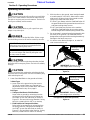
Operating Checklist
✔ Check Referenc
Check 3-Point Hook-up procedure. Be sure all
pins have been installed and are secured.
Page 9
Check Pull Type Hook-up procedure. Be sure
hitch pin or ball hitch is secured to the draw bar.
Page 10
Check optional rear scraper. Make sure it has
been adjusted and all bolts are tight.
Page 11
Check ball hitch swivel. Make sure the swivel
nut is properly tightened.
Page 11
Make sure the operator has read and knows
how to operate the Seed Bed Roller.
Page 12
Make sure the Seed Bed Roller has been
lubricated as required.
Page 16
Check Seed Bed Roller initially and periodically
for loose bolts & pins, Tighten bolts to the
correct torque.
Page 21
Make the following inspections if the Seed Bed
Roller is attached to a drawbar:
1. Inspect safety equipment of the machine pulling the
Seed Bed Roller. Make sure the machine is in good
working condition.
2. Inspect levelness of tongue when setting-up. See
“Important Note” in box on page 8. Turn hitch
assemblyover ifneededbyremovingbolts(#10) and
pins (#17) shown in Figure 1-2 on page 8. Replace
bolts and pins with clips after turning hitch assembly
over. Be sure to tighten the nuts to the correct torque.
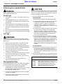
Transporting
!
CAUTION
When traveling on public roads at night or during the day, use
accessory lights and devices for adequate warning to
operators of other vehicles. Comply with all federal, state and
local laws.
1. The 3-Point Seed Bed Roller should be lifted as high
as possible to clear the ground when transporting.
2. The frame and scrapers on the pull type Seed Bed
Roller are low to the ground while in transport
position. Be careful notto hitobjects protruding from
the ground with the Seed Bed Roller.
3. Leave enough clearance on both sides of the Seed
Bed Roller when traveling straight and when making
turnsto keeptheunit fromcontacting obstacles such
as buildings, trees and fences. Always reduce
ground speed when turning.
4. Select a safe groundtravel speedwhen transporting
from one area to another. Do not travel over 10 MPH
while carrying the Seed Bed Roller on its wheels.
5. Always travel on roadways in such a way that faster
moving vehicles may pass you safely.
6. Slow down when traveling over rough or hilly terrain.
7. Never back-up with the Seed Bed Roller down.
8. Be aware of negative hitch weight on the pull type
SeedBedRollerwhenintransporting.Negativehitch
weight can cause loss of vehicle control. Add weight
to the rear of the vehicle if needed.
9. Do not transport on a public roads with roller down.
Damage to unit and/or road may occur.
Section 3: Operating Procedures

13
Section 3: Operating Procedures
2/23/09
Model SBR48, SBR60 & SBR72 Seed Bed Roller 322-215M
Land Pride
Table of Contents
Operating Instructions
!
CAUTION
Be careful when lowering the pull type roller to ground. Make
sure no one is under, behind or near the unit when lowering.
The roller is very heavy and can crush someone. The hitch can
also flip over suddenly and hit someone.
!
CAUTION
Do not use the Seed Bed Roller to pull or push fence post,
stumps or any other object.
!
DANGER
Do not carry a rider on the Seed Bed Roller. Riders can get
hurt while being carried or fall and be crushed by the roller.
!
CAUTION
Be aware of negative hitch weight when unhooking the Seed
Bed Roller while in transport position. The hitch can suddenly
swing up.
!
CAUTION
Be aware of positive hitch weight when unhooking the Seed
Bed Roller while in field position. The hitch can suddenly drop
while unhooking the unit.
1. Lower Seed Bed Roller to the ground as follows:
3-Point Type:
a. Lower roller to the ground using the tractor’s
3-Point lift controls. Make any required final
adjustments to the3-Point lowerarms andcenter
link as outlined in step 10 on page 9.
Pull-Type:
a. Transport Position to Field Position:
Lower roller to ground by unhooking from the
pulling machine and lifting up and rotating the
hitch 180
o
up over the roller body as shown in
Figure 3-1. Re-hook hitch to the drawbar. If using
ball hitch, rotate ball hitch 180
o
to re-hookup.
b. Field Position to Transport Position:
Raise roller for transporting by unhooking from
the pulling machine, lifting up and rotating the
hitch 180
o
up over the roller body as shown in
Figure 3-2. Re-hook hitch tothe machine. If using
ball hitch, rotate ball hitch 180
o
to re-hookup.
IMPORTANT: Damage to the 3-Point Seed Bed
Roller can occur if the unit is not raised off of the
ground before making sharp turns.
IMPORTANT: Damage to pull type Seed Bed Roller
can occur to tongue and machine pulling the unit if
too sharp a turn is made.
2. With the roller on the ground, travel straight forward
at a safe speed of 3 to 5 MPH. Allow room to make
wide turns or lift the unit out of the ground to make
sharp turns. Make wide turns when:
• 3-Point Type: Always raise the Seed Bed Roller off
theground before turning aroundat the end ofa run
and when making sharp corners.
• Pull-Type: Make sure the tires on the machine
pulling the Seed Bed Roller do not make contact
with the tongue and if attached, drag harrow chain.
3. Do not operate in reverse (traveling backwards) with
the roller on the ground. The Seed Bed Roller is
designedforworkingsoilwhiletravelingforwardonly.
Damage to the frame may occur.
4. It is best to cross ditches straight on, to make full
roller contact with the soil.
Pull-Type Set-Up (Transport Set-Up Shown)
Figure 3-1
Pull-Type Set-Up (Field Set-Up Shown)
Figure 3-2
Rotate Hitch 180
o
Over
Roller Body To Change
to Field Set-Up.
IMPORTANT: Beware of negative
hitch weight when unhooking.
25782
25762
Rotate Hitch 180
o
Over
Roller Body To Change to
Transport Set-Up
IMPORTANT: Beware of positive
hitch weight when unhooking.

14
Section 3: Operating Procedures
Model SBR48, SBR60 & SBR72 Seed Bed Roller 322-215M
2/23/09
Land Pride
Table of Contents
Unhooking the Seed Bed Roller
!
DANGER
Always engage parking brake, shut off tractor and remove key
before dismounting from tractor.
3-Point Type
1. See Figure 1-1 on page 7. Set support stand in park
position.
2. Lower Seed Bed Roller onto a level solid surface.
The roller may start rolling while unhooking if not on
level ground.
3. Shut tractor engine off and engage parking brake.
4. Ensurethattheunitisstable.Chockfrontandbackof
rear roller if needed especially if unit is not on level
ground.
5. Disconnect top center link from the SeedBed Roller.
6. Disconnect the lower 3-Point lift arms from the Seed
Bed Roller.
Pull Type
!
WARNING
Chock front and back of roller when using support stand to
prevent unit fromrolling and causing property damage and/or
bodily injury.
1. Park on a level solid surface. The roller may start
rolling while unhooking if not on level ground.
2. Shut vehicle engine off and engage parking brake.
3. Ensurethattheunitisstable.Chockfrontandbackof
rear roller to prevent unit from rolling.
4. Disconnect clevis hitch or ball hitch from machine
towing the Seed Bed Roller.
5. Ifintransport,rotatehitch180
o
overtherollerbodyto
rest unit on the rollers and not on the wheels.
6. Set support stand in park position. (See Figure 3-5
on page 15.)
7. See Storage Instructions below for alternate
positions to store pull type unit.
Storage Instructions
Clean Seed Bed Roller at the end of the working season
or when the roller will not be used for a long period.
1. Clean off any dirt or grease that may have
accumulated on the roller and moving parts. Scrape
off compacted dirt and then wash the surface
thoroughly with a garden hose.
2. Inspect for loose, damaged or worn parts and adjust
or replace as needed.
3. Lubricate as noted in the Lubrication portion of this
section starting on page 16.
!
CAUTION
Be careful when lowering the pull type roller to ground. Make
sure no one is under, behind or near the unit when lowering.
The roller is very heavy and can crush someone. The hitch can
also flip over suddenly and hit someone.
4. Store Seed Bed Roller in a clean, dry place.
Pull-Type Units
There are three methods of storing pull-type units:
• Position unit on a flat level surface. Raise pull hitch
up until unit is resting on its rear wheels and
scrapers as shown in Figure 3-3. Use auxiliary
supports or posts if necessary to prevent the
possibility of the unit tipping over. Chock front and
back of wheels.
• Position unit on a flat level surface. Raise pull hitch
up until the unit is resting on its rear roller and
scrapers as shown in Figure 3-4. Ensure unit is
stable. Use auxiliary supports or posts if necessary
to prevent the possibility of the unit tipping over.
Chock front and back of roller.
• Do not leave unit resting on its wheels (transport
position) and hitch support. The hitch can develop
negative weight and swing up on its own. Instead,
position unit on a flat level surface. Rotate hitch up
and over 180
o
until unit is resting on the hitch
support and rear roller as shown in Figure 3-5.
Ensure unit is stable by chocking the front and back
of roller.
3-Point Lift Units
• Position unit on a flat level surface. Lower 3-Point
hitch until the rear roller and support stand are
restingon the ground. Ensure that the unit is stable.
Chockrearrollerifneeded especiallyifunitisnot on
level ground.
5. Repaint where paint is worn or scratched to prevent
rust. Ask your dealer for Land Pride touch-up paint.
Land Pride Aerosol Touch-up Paint
Part No. Part Description
821-011C PAINT LP BEIGE AEROSOL SPRAY CAN
821-002C PAINT LP BLACK AEROSOL SPRAY CAN
821-054C PAINT MEDIUM RED AEROSOL SPRAY CAN
821-058C PAINT GREEN AEROSOL SPRAY CAN
821-066C PAINT ORANGE AEROSOL SPRAY CAN
821-067C PAINT BLUE AEROSOL SPRAY CAN

15
Section 3: Operating Procedures
2/23/09
Model SBR48, SBR60 & SBR72 Seed Bed Roller 322-215M
Land Pride
Table of Contents
Storage Positions For Tight Areas
Figure 3-3
Storage Positions For Tighter Areas
Figure 3-4
Storage Position Using Support Stand
Figure 3-5
Stored Supported on Rear
Wheels & Scraper
25798
Chock Front & Back of Wheels
Stored Supported on Rear
Roller & Scraper
25798
ChockBack
of Roller
Stored Supported on the Roller & Support Stand
25798
Chock Front & Back of Roller
General Operating Instructions
!
WARNING
Do not use the roller for pulling fence posts, stumps, etc.,
lifting objects, carry objects or towing other equipment. Any
of the above can result in roller damage, serious bodily injury
or death.
!
DANGER
Never carry a person on the roller. A person can fall and be
ran over by the roller or tractor causing serious injury or
death.
By now you shouldhave read the operator’smanual and
familiarized yourself with all of the possible applications
and mounting instructions for your Land Pride Seed Bed
Roller. You should now also be familiar with
recommended safety and maintenance procedures. It’s
time to put your new Seed Bed Roller to work. Whether
you have a three-point hitch mounted model or a pull-
type, it will be important to maintain a ground speed
below 7 miles per hour. Driving faster than 7 mph can
result in causing your roller to bounce and not deliver the
surface finish and seed to soil contact required for
maximumgermination.Itis alsobestto avoidsharpturns
if you want to maintain a uniform finish. The soil should
have a very dry texture to it when rolling seed into firmer
contact withthesoil. Wet or sticky soil will build up on the
rolleronly to bescraped off and deposited onthe surface
in non-uniform clumps by the roller scrapers. If you are
rollingto press seed down in anOverseeding application
on pasture or turf grass,it is also important towait till the
grass is dry to avoid accumulations of seed build up
sticking to the roller.
If you are transporting a pull-type Seed Bed Roller from
one location to another, it is important to remember that
the 10" transport wheels are for low speed use and
therefore a 10 mph top transport speed should not be
exceeded.It is alsoimportant to notethat in thetransport
mode you have approximately5" of groundclearance so
take care not to drive over larger rocks, debris, and
protruding tree roots. Never pull onto hard surfaces or
paved areas with the roller on the ground or excessive
wear and damage may occur. The LandPride Seed Bed
Roller is a very user friendly attachment and with a little
practiceyoushould beginto achieveprofessional results
in no time at all. See Specifications and Feature Benefits
sections on pages 19 & 20 for additional information.

16
Section 4: Maintenance & Lubrication
Model SBR48, SBR60 & SBR72 Seed Bed Roller 322-215M
2/23/09
Land Pride
Table of Contents
Maintenance
!
CAUTION
Do not work on or around the Seed Bed Roller without
blocking the unit properly. The roller raised off the ground
could drop suddenly crushing someone. If the roller is on the
ground, it could roll onto someone crushing that person.
Properservicingand adjustmentisthe keytothe longlife
of any implement. With careful and systematic
inspection, you can avoid costly maintenance, time and
repair.
Section 4: Maintenance & Lubrication
Roller Flange Bearings
Number of Zerks: 2
Type of Lubrication: Multi-purpose Grease
Quantity = 2 pumps
Lubrication
25797
25796
50
hrs
Multi-purpose
spray lube
Multi-purpose
grease lube
Multi-purpose
oil lube
Intervals in hours at which
lubrication is required
Lubrication
Legend
8
Hours
Wheel Bearings
Number of Zerks: 2
Type of Lubrication: Multi-purpose Grease
Quantity = 2 pumps
8
Hours
After using your Seed Bed Roller for several hours,
check all bolts to be sure they are tight. Loose bolts can
damage the unit and/or hurt someone especially if the
roller falls from the support frame.
Always use genuine Land Pride replacement parts. Any
Land Pride equipment that has been altered or modified
without Land Pride’sspecific recommendation, approval
and authorization in writing excludes the warranty.
Replace any worn, damaged or illegible safety labels by
obtaining new labels from your Land Pride Dealer.

17
Section 5: Additional Equipment
2/23/09
Model SBR48, SBR60 & SBR72 Seed Bed Roller 322-215M
Land Pride
Table of Contents
Section 5: Additional Equipment
Electric Spin Spreader, Mounting Bracket & Rear Hitch
Figure 5-2
Drag Harrow
Refer to Figure 5-3:
The Land Pride Drag Harrows are designed for various
types of seedbed and ground preparations. They can be
used to smooth out freshly cultivated soil, work seed and
fertilizerintofreshlycultivated soilorintoturfand pasture
grass, fluff and level arenas, aerate soil for faster
dry-downtime,de-thatchandaeratelawnsandpastures,
break up aeration cores on turf surfaces and groom
snow-packed ski resorts.
The Drag Harrow can also be used in tandem with Land
Pride’s Disc Harrow, Electric Spin Spreader and Seed
Bed Roller to provide a highly efficient and complete
seeding application in one pass. See “Complete One
Pass Seeding Application” on page 18.
Land Pride Drag Harrow Models
Model DRG04 . . . . . . . . . . . . . . . . 4 ft. wide x 4 ft. long
Model DRG06 . . . . . . . . . . . . . . . . 6 ft. wide x 4 ft. long
Model DRG08 . . . . . . . . . . . . . . . . 8 ft. wide x 4 ft. long
Drag Harrow (6’ x 4" Shown)
Figure 5-3
Rear Hitch
Spin Spreader
Mounting Bracket
2560
9
2561
1
Additional Seeding Equipment
Disc Harrow
Refer to Figure 5-1:
Land Pride Disc Harrows are designed to open and
break up soil surface in preparation for planting.
Land Pride
Disc Harrow Models
Model DH1048 & DH1060. . . . . . . . . . . 48" & 60" Wide
Model DH1560 & DH1572 . . . . . . . . . . .60" & 72" wide
Model DH2572 & DH2584 . . . . . . . . . . .72" & 84" wide
Additional equipment can be attached behind the Disc
Harrow to make it a complete seeding package. See
“Complete One Pass Seeding Application” on page 18.
Disc Harrow Assembly (DH Series)
Figure 5-1
Electric Spin Spreader
Refer to Figure 5-2:
The Land Pride Electric Spin Spreader is a highly
versatile package designed to plant or spread seeds,
fertilizer, lime, gypsum, and other soil conditioning
amendments at distances ranging from 4 ft. to 20 ft. It
can also be usedin theoff-season tospread sand orsalt
for winter icing or slick snow conditions.
The unit has a 12 Volt remote tether control that can be
operatedrightfromthedriverseattoturnthespreaderon
or off or to set the seed-gate opening to different
application rates.
The Spin Spreader has applications in overseeding of
pastures, grassy runways, open areas, roadsides,
medians, wild game food plots, hunting clubs, hunting
resorts, ranches, farms, game preserves, landscaping,
andhobbyfarming.Italsoworksverywellingardensand
nurseries to incorporate fertilizer and pelletized gypsum
or lime as soil amendments.
Accessories are available for mounting the spreader to a
2" receiver hitch on a utility vehicle or to a Land Pride
Disc Harrow. A rear hitch can be attached to the Disc
Harrow Spin Spreader mounting bracket. The Drag
Harrow and Seed Bed Roller can then be hitched to the
rear hitch. See “Complete One Pass Seeding
Application” on page 18.
1780
0

18
Section 5: Additional Equipment
Model SBR48, SBR60 & SBR72 Seed Bed Roller 322-215M
2/23/09
Land Pride
Table of Contents
Complete One Pass Seeding Application
Refer to Figure 5-4:
Land Pride offers a Seeder/Overseeder component
system for one-pass ground cultivation and seed to soil
integration for applications on previously tilled soil,
existingpasture ground, large grassy areas, reclamation
sitesand wild gamefoodplots. This systemis comprised
of a Land Pride Disc Harrow, rear mounted Electric Spin
Spreader with specialhitch kit,trailing DragHarrow, and
trailing Pull-type Seed Bed Roller.
Seeyournearest LandPride Dealerfor moreinformation
or visit our web site at www.landpride.com.
Complete One Pass Seeding Application
Figure 5-4
2580
2
Page is loading ...
Page is loading ...
Page is loading ...
Page is loading ...
Page is loading ...
Page is loading ...
-
 1
1
-
 2
2
-
 3
3
-
 4
4
-
 5
5
-
 6
6
-
 7
7
-
 8
8
-
 9
9
-
 10
10
-
 11
11
-
 12
12
-
 13
13
-
 14
14
-
 15
15
-
 16
16
-
 17
17
-
 18
18
-
 19
19
-
 20
20
-
 21
21
-
 22
22
-
 23
23
-
 24
24
-
 25
25
-
 26
26


Ask a question and I''ll find the answer in the document
Finding information in a document is now easier with AI
Related papers


Other documents
-
BCS 32" Power Harrow Owner's manual
-
 Red Rock 8578775 Owner's manual
-
Swisher 12593 Owner's manual
-
 Yard Tuff DH-045 Owner's manual
-
Grizzly G8732 User manual
-
Toolots 8LR5IEJRF User manual
-
Simplicity 206 User manual
-
 AGT INDUSTRIAL AGT-NTSD-7 Owner's manual
-
BE DHXXXN 3 PT Disc Harrow User manual
-
Toro Seeder Box Kit, Soil Cultivator Attachment for Compact Utility Loader Installation guide


