
1010455-2-A
2002 Kohler Co.
Español, Página 6
Français, Page 11
BEFORE YOU BEGIN
HOW TO USE THESE INSTRUCTIONS
Please read these instructions carefully to familiarize
yourself with the required tools, materials, and installation
sequences. Follow the sections that pertain to your
particular installation. This will help you avoid costly
mistakes. In addition to proper installation, read all
operating and safety instructions.
All information in these instructions is based on the latest
product information available at the time of publication.
Kohler Co. reserves the right to make changes in product
characteristics, packaging, or availability at any time
without notice.
NOTES
Observe all local plumbing and building codes.
Inspect waste and supply tubing; replace if
necessary.
If you are installing a new bath, install the drain
before installing the bath. Refer to the
manufacturer’s installation instructions.
Adjustable pop-up drain has removable parts.
Drain “T” is reversible for vertical or horizontal
drainage.
K-7166 and K-7166M is for Seawall 6’ (1.8m)
bath or whirlpool and 14” (35.6cm) Mayflower
bath.
TOOLS REQUIRED
Assorted screwdrivers
Adjustable or open end wrench
Pipe wrenches
Pliers
Plumbers putty
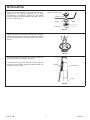
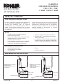
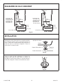
ROUGHING-IN
Fig. #1
2-7/8” (7.3cm)
3” (7.6cm)
1-1/2” N.P.S.
1-1/2” O.D.
7” (17.8cm)
17” (43.2cm) BATH =
14-3/4” (37.5cm)
24” (61cm) BATH =
21-1/2” (54.6cm)
2-7/8” (7.3cm)
3” (7.6cm)
1-1/2” N.P.S.
1-1/2” O.D.
7” (17.8cm)
14” (35.6cm) BATH =
11-1/2” (29.2cm)
16” (40.6cm) BATH =
14” (35.6cm)
K-7160
K-7161 K-7161M
K-7160M

2
1010455-2-A
Kohler Co.
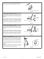
INSTALLATION
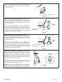
Apply a ring of plumbers putty or other sealant around the
underside of the strainer according to the putty
manufacturer’s instructions. Position the flat gasket
between the drain ell and the bottom of the bath. Turn the
strainer into the drain ell.
Fig. #2
Drain Ell
Gasket
Strainer
Bath
Apply Plumbers Putty
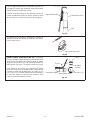
Tighten the drain ell securely by inserting pliers handles
into the top of the strainer, as shown. Make sure the drain
ell tube is facing the front of the bath. Remove any excess
sealant.
Fig. #3
Attach the gasket to the overflow ell, as shown. Make sure
the tapered end of the gasket is facing up.
Lubricate the O-rings on the overflow ell, and insert the
overflow ell into the tube. Align the overflow ell with the
overflow hole in the bath.
Fig. #4
Overflow Ell
Gasket
Tube

3
1010455-2-A
Kohler Co.
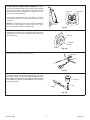
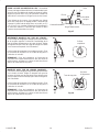
From inside the bath, assemble hold down plate to
overflow ell with screws provided. Tighten all screws.
Fig. #5
Hold Down Plate
FOR BELOW FLOOR INSTALLATIONS: Assemble the
nut and gasket on the drain ell, and the nut and cone
washer on the tube. Align the parts with the tee, as shown.
Insert the tubes completely into the tee. Align and tighten
the nuts.
Attach the tailpiece to the tee, and tighten. The tailpiece
may need to be cut for proper fit. The tailpiece should fit
inside the trap 1” (2.5cm) to 2” (5cm). Install the bath
according to the manufacturer’s installation instructions.
Make sure the drain tailpiece fits properly into the trap.
Fig. #6
Tube
Nuts
Drain Ell
Tee
Gasket
Cone
Washer
FOR ABOVE FLOOR INSTALLATIONS: Assemble the
nut and gasket on the drain ell, and the nut and cone
washer on the tube. Align the parts with the tee, as shown.
Insert the tubes completely into the tee. Align and tighten
the nuts.
Attach the tailpiece to the tee, and tighten. The tailpiece
may need to be cut for proper fit. The tailpiece should fit
inside the trap 1” (2.5cm) to 2” (5cm). Install the bath
according to the manufacturer’s installation instructions.
Make sure the drain tailpiece fits properly into the trap.
Fig. #7
Tube
Nuts
Drain Ell
Tee
Gasket
Cone
Washer
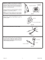
MULTIPLE LIFT ROD MODELS: Choose the lift rod that
extends most closely to the necessary length. Position the
lift rod assembly directly on the drain stopper. Adjust the
assembly length so the eye of the lift rod is centered over
either top hole of the overflow ell. Refer to the illustration.
Insert the lift rod assembly into the overflow ell. Tighten
the overflow hood to the overflow ell with the two screws
provided.
NOTE: For installations where the overflow hood will be
exposed to high volumes of direct water spray, apply
silicone sealant around the overflow hood.
Fig. #8
Top Holes

4
1010455-2-A
Kohler Co.
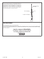
ATTACHED LIFT ROD ASSEMBLY MODELS: Position
the lift rod assembly directly on the drain stopper. Adjust
the assembly length so the alignment ribs of the overflow
hood line up with the top edge of the overflow hole in the
bath. Refer to the illustration.
Insert the lift rod assembly into the overflow ell. Tighten
the overflow hood to the overflow ell with the two screws
provided.
NOTE: For installations where the overflow hood will be
exposed to high volumes of direct water spray, apply
silicone sealant around the overflow hood.
Fig. #9
Alignment
Ribs
Overflow
Hole
Assemble the handle to the overflow hood with the screw
provided. It may be necessary to adjust the handle to the
desired position.
Fig. #10
Handle
Overflow
Hood
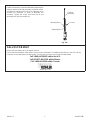
Insert the drain stopper into the drain ell.
Fig. #11
The drain stopper should rise approximately 3/8” (1cm)
above the strainer.
Fig. #12
Nut
Stopper
Toggle

5
1010455-2-A
Kohler Co.
If sufficient clearance cannot be obtained by adjusting the
stopper, remove the lift rod assembly. Loosen the screw,
and slide the adjusting block up on the adjusting rail to
increase the clearance, or down to decrease the
clearance. Tighten the screw, and insert the lift rod
assembly back into the overflow ell.
Fig. #13
Lift Rod
Assembly
Screw
Adjusting Block
Adjusting Rail
CALL US FOR HELP
Here’s what you need to do if you require service:
First review the installation instructions to ensure correct installation. For additional assistance in the USA, call our
Customer Service Department for direct help. You may also contact us at our web site listed below.
Call 1-800-4-KOHLER within the U.S.
Call 001-877-680-1310 within Mexico
Call 1-800-964-5590 within Canada

6
1010455-2-A
Kohler Co.
ANTES DE COMENZAR
CÓMO UTILIZAR LAS INSTRUCCIONES
Lea estas instrucciones atentamente para familiarizarse
con las herramientas requeridas, los materiales y la
secuencia de instalación. Siga las secciones
correspondientes a su instalación particular. Esto le
ayudará a evitar errores costosos. Para una buena
instalación, lea todas las instrucciones de funcionamiento
y de seguridad.
Toda la información contenida en las instrucciones está
basada en la información más reciente disponible al
momento de su publicación. Kohler Co. se reserva el
derecho de efectuar cambios en las características del
producto, empaque o disponibilidad en cualquier
momento, sin previo aviso.
NOTAS
Cumpla con todos los códigos locales de
plomería y de construcción.
Revise con cuidado las tuberías de alimentación
y de desagüe para ver si están dañadas.
Reemplace de ser necesario.
Si está instalando una bañera nueva, instale el
drenaje antes de instalar la bañera. Consulte las
instrucciones de instalación del fabricante.
El drenaje ajustable tiene partes removibles.
El drenaje de “T” es reversible para el drenaje
vertical y horizontal.
Los modelos K-7166 y K-7166M corresponden a
la bañera regular o de hidromasaje Seawall de 6’
(1,8m) y a la bañera Mayflower de 14” (35,6cm).
HERRAMIENTAS REQUERIDAS
Variedad de destornilladores
Llave ajustable o llave de boca
Llave para tubos
Pinzas
Masilla de plomería
DIAGRAMA DE INSTALACIÓN
Fig. #1
2-7/8” (7,3cm)
3” (7,6cm)
1-1/2” N.P.S.
1-1/2” DIÁM. EXT.
7” (17,8cm)
BAÑERA DE 17” (43,2cm) =
14-3/4” (37,5cm)
BAÑERA DE 24” (61cm) =
21-1/2” (54,6cm)
2-7/8” (7,3cm)
3” (7,6cm)
1-1/2” N.P.S.
1-1/2” DIÁM. EXT.
7” (17,8cm)
BAÑERA DE 14” (35,6cm) =
11-1/2” (29,2cm)
BAÑERA DE 16” (40,6cm) =
14” (35,6cm)
K-7160
K-7161
K-7161MK-7160M
Page is loading ...
Page is loading ...
Page is loading ...
Page is loading ...
Page is loading ...

12
1010455-2-A
Kohler Co.
DIAGRAMME DE RACCORDEMENT
Fig. #1
2-7/8 po
(7,3 cm)
3 po (7,6 cm)
1-1/2 po N.P.S.
1-1/2 po DIA. EXT.
7 po
(17,8 cm)
BAIGNOIRE DE
17 po (43,2 cm) =
14-3/4 po (37,5 cm)
BAIGNOIRE DE
24 po (61 cm) =
21-1/2 po (54,6 cm)
2-7/8 po
(7,3 cm)
3 po (7,6 cm)1-1/2 po N.P.S.
1-1/2 po DIA. EXT.
7 po
(17,8 cm)
BAIGNOIRE DE
14 po (35,6 cm) =
11-1/2 po (29,2 cm)
BAIGNOIRE DE
16 po (40,6 cm) =
14 po (35,6 cm)
K-7160
K-7161
K-7161M
K-7160M
INSTALLATION
Appliquer du mastic d’étanchéité ou un produit semblable
sur le dessous du drain selon la notice du fabricant du
mastic. Positionner la bague d’étanchéité plate entre le
coude de drain et le fond de la baignoire. Tourner la
crépine dans le coude de drain.
Fig. #2
Coude d’évacuation
Bague d’étanchéité
Crépine
Baignoire
Appliquer du mastic
Serrer le coude du drain solidement en insérant les
poignées d’une paire de pince dans la crépine, tel
qu’indiqué. S’assurer que le tube en L du drain fait face à
l’avant de la baignoire. Enlever tout excédant de mastic.
Fig. #3
Page is loading ...
Page is loading ...

15
1010455-2-A
Kohler Co.
Assembler le levier au couvercle de trop-plein à l’aide de
la vis fourni. Le réglage du levier à la position désirée peut
être requis.
Fig. #10
Levier
Abat-vent de trop-plein
Insérer la butée de drain dans le coude de drain.
Fig. #11
Le butoir de drain doit être soulevé d’environ 3/8 po (1 cm)
au-dessus de la crépine.
Fig. #12
Écrou
Bouchon
Articulation

16
1010455-2-A
Kohler Co.
Enlever la tige de levage s’il est impossible d’obtenir un
dégagement suffisant en réglant le butoir. Desserrer la vis
et faire glisser le bloc de réglage sur le longeron de
réglage vers le haut pour augmenter ou vers le bas pour
diminuer l’écart. Serrer la vis et insérer l’assemblage de
la tige de levage dans le coude de trop-plein.
Fig. #13
Ensemble de tige
de levage
Vis
Bloc de réglage
Longeron de réglage
BESOIN D’AIDE ?
Pour demander du service, voici comment faire.
Revoir d’abord la notice d’installation pour s’assurer d’une installation correcte. Pour toute assistance additionnelle,
contactez notre département de service à la clientèle. Vous pouvez aussi nous joindre sur notre site Web à l’adresse
donnée ci-dessous.
Aux É.-U., composer le 1-800-4-KOHLER
Au Mexique, composer le 001-877-680-1310
Au Canada, composer le 1-800-964-5590
-
 1
1
-
 2
2
-
 3
3
-
 4
4
-
 5
5
-
 6
6
-
 7
7
-
 8
8
-
 9
9
-
 10
10
-
 11
11
-
 12
12
-
 13
13
-
 14
14
-
 15
15
-
 16
16


Ask a question and I''ll find the answer in the document
Finding information in a document is now easier with AI
in other languages
- français: Kohler K-7166-AF-CP Guide d'installation
- español: Kohler K-7166-AF-CP Guía de instalación
Related papers
-
Kohler K-7145-SN Installation guide
-
-
-
-
-
-
-
-
-
Kohler K-11677-CP Installation guide
Other documents
-
Belle Foret BFNLD4PB Installation guide
-
Glacier Bay 7043-002CHP5 Installation guide
-
Delta Faucet RP391PB Installation guide
-
-
Jacuzzi JOF6732BUXXXXG Installation guide
-
Jacuzzi AZF6731BCXXXXW Installation guide
-
Everbilt WO-1-CR-EZ Installation guide
-
DANCO 51933 Installation guide
-
-