Cobalt Digital 9960-TG2-REF1 3G/HD/SD-SDI Dual Test Signal Generator User manual
- Type
- User manual

2506 Galen Drive
Champaign, IL 61821
Voice 217.344.1243 • Fax 217.344.1245
www.cobaltdigital.com
Product Manual
9960-TG2REF1-OM (V1.4)
Cobalt Digital Inc.
3G/HD/SD-SDI Dual Test Signal Generator
with Moving Box Active Signal Indication and Bi-Level/Tri-Level
Sync Out
9960-TG2-REF1
9960-TG2-REF1

Copyright
©Copyright 2018, Cobalt Digital Inc. All Rights Reserved.
Duplication or distribution of this manual and any information contained within is strictly prohibited without the express written
permission of Cobalt Digital Inc. This manual and any information contained within, may not be reproduced, distributed, or
transmitted in any form, or by any means, for any purpose, without the express written permission of Cobalt Digital Inc.
Reproduction or reverse engineering of software used in this device is prohibited.
Disclaimer
The information in this document has been carefully examined and is believed to be entirely reliable. However, no responsibility
is assumed for inaccuracies. Furthermore, Cobalt Digital Inc. reserves the right to make changes to any products herein to improve
readability, function, or design. Cobalt Digital Inc. does not assume any liability arising out of the application or use of any
product or circuit described herein.
Trademark Information
Cobalt
®
is a registered trademark of Cobalt Digital Inc.
openGear
®
is a registered trademark of Ross Video Limited. DashBoard™ is a trademark of Ross Video Limited.
Dolby
®
is a registered trademark of Dolby Laboratories, Inc. Other product names or trademarks appearing in this manual are the
property of their respective owners.
Congratulations on choosing the Cobalt
®
9960-TG2-REF1 3G/HD/SD-SDI Dual Test Signal Generator with
Moving Box Active Signal Indication and Bi-Level/Tri-Level Sync Out. The 9960-TG2-REF1 is part of a full
line of modular processing and conversion gear for broadcast TV environments. The Cobalt Digital Inc. line
includes video decoders and encoders, audio embedders and de-embedders, distribution amplifiers, format
converters, remote control systems and much more. Should you have questions pertaining to the installation or
operation of your 9960-TG2-REF1, please contact us at the contact information on the front cover.
Manual No.: 9960-TG2REF1-OM
Document Version: V1.4
Release Date: August 1, 2018
Applicable for
Firmware Version
(or greater):
2.056 or greater
Description of
product/manual
changes:
- Update manual for latest card functionality, including new standard
features. (This firmware version has significant user interface
changes versus prior firmware versions and the use of this new
Product Manual is strongly recommended.)
- Correction to manual of minor errata and consistency items.
9960-TG2REF1-OM (V1.4)

9960-TG2REF1-OM (V1.4) 9960-TG2-REF1 PRODUCT MANUAL i
Table of Contents
Chapter 1 Introduction . . . . . . . . . . . . . . . . . . . . . . . . . . . . . . . . . . . . . . . . . . . 1-1
Overview ................................................................................................................ 1-1
9960-TG2-REF1 Card Software Versions and this Manual................................... 1-2
Cobalt Reference Guides........................................................................................ 1-2
Manual Conventions............................................................................................... 1-3
Warnings, Cautions, and Notes .................................................................. 1-4
Labeling Symbol Definitions...................................................................... 1-4
Safety and Regulatory Summary............................................................................ 1-5
Warnings..................................................................................................... 1-5
Cautions...................................................................................................... 1-5
EMC Compliance Per Market .................................................................... 1-5
9960-TG2-REF1 Functional Description............................................................... 1-6
9960-TG2-REF1 Outputs........................................................................... 1-6
Video TSG Description .............................................................................. 1-8
ANC Generator Description....................................................................... 1-8
Video Output Crosspoint............................................................................ 1-9
De-Embed Audio Processor Description.................................................... 1-9
Control and Data Input/Output Interfaces ................................................ 1-10
User Control Interface .............................................................................. 1-11
9960-TG2-REF1 Rear I/O Modules......................................................... 1-13
Technical Specifications....................................................................................... 1-13
Contact Cobalt Digital Inc.................................................................................... 1-15
Warranty and Service Information ....................................................................... 1-16
Cobalt Digital Inc. Limited Warranty....................................................... 1-16
Chapter 2 Installation and Setup . . . . . . . . . . . . . . . . . . . . . . . . . . . . . . . . . . . 2-1
Overview ................................................................................................................ 2-1
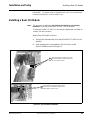
Installing the 9960-TG2-REF1 Into a Frame Slot.................................................. 2-1
Installing a Rear I/O Module.................................................................................. 2-3
9960-TG2-REF1 Rear I/O Modules........................................................... 2-4
GPIO, Serial (COMM), and Analog Audio Connections....................................... 2-5
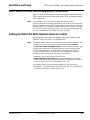
Setting Up 9960-TG2-REF1 Network Remote Control......................................... 2-5
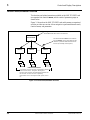
Chapter 3 Operating Instructions. . . . . . . . . . . . . . . . . . . . . . . . . . . . . . . . . . . 3-1
Overview ................................................................................................................ 3-1

ii 9960-TG2-REF1 PRODUCT MANUAL 9960-TG2REF1-OM (V1.4)
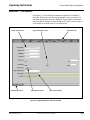
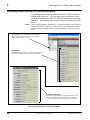
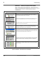
Control and Display Descriptions........................................................................... 3-1
Function Menu/Parameter Overview.......................................................... 3-2
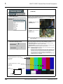
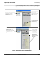
DashBoard™ User Interface....................................................................... 3-3
Cobalt
®
Remote Control Panel User Interfaces .......................................... 3-4
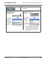
Web HTML5 User Interface ....................................................................... 3-5
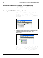
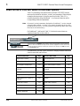
Accessing the 9960-TG2-REF1 Card via Remote Control..................................... 3-6
Accessing the 9960-TG2-REF1 Card Using DashBoard™........................ 3-6
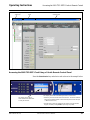
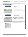
Accessing the 9960-TG2-REF1 Card Using a Cobalt
®
Remote
Control Panel............................................................................................... 3-7
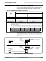
Checking 9960-TG2-REF1 Card Information ........................................................ 3-8
Ancillary Data Line Number Locations and Ranges .............................................. 3-9
9960-TG2-REF1 Function Menu List and Descriptions....................................... 3-10
Input Video Controls ................................................................................ 3-11
Output Video Mode Controls ................................................................... 3-11
SDI Output Format/Select ........................................................................ 3-12
Logo Upload/Insertion Controls .............................................................. 3-15
Analog Output Video ............................................................................... 3-16
Output Audio Routing/Controls ............................................................... 3-18
Clock (Wall-Clock Time/LTC) Controls ................................................. 3-22
Timecode Controls ................................................................................... 3-23
Reticules ................................................................................................... 3-28
Video Proc Controls ................................................................................. 3-31
Closed Captioning .................................................................................... 3-32
Character Burner ...................................................................................... 3-33
Moving Box Insertion .............................................................................. 3-38
SCTE 104 Insertion Controls ................................................................... 3-39
ANC Test Packet Insertion Controls ........................................................ 3-40
COMM Ports Setup Controls ................................................................... 3-41
GPO Setup Controls ................................................................................. 3-41
Presets ...................................................................................................... 3-42
Event Setup Controls ................................................................................ 3-44
Admin ....................................................................................................... 3-48
User Log ................................................................................................... 3-51
Troubleshooting .................................................................................................... 3-52
Error and Failure Indicator Overview....................................................... 3-52
Basic Troubleshooting Checks.................................................................. 3-56
9960-TG2-REF1 Processing Error Troubleshooting ................................ 3-57
Troubleshooting Network/Remote Control Errors.................................... 3-58
In Case of Problems .................................................................................. 3-58

9960-TG2REF1-OM (V1.4) 9960-TG2-REF1 PRODUCT MANUAL 1-1
Chapter 1
Chapter 1 Introduction
Overview
This manual provides installation and operating instructions for the
9960-TG2-REF1 3G/HD/SD-SDI Dual Test Signal Generator with Moving
Box Active Signal Indication and Bi-Level/Tri-Level Sync Out card (also
referred to herein as the 9960-TG2-REF1).
This manual consists of the following chapters:
• Chapter 1, “Introduction” – Provides information about this manual
and what is covered. Also provides general information regarding the
9960-TG2-REF1.
• Chapter 2, “Installation and Setup” – Provides instructions for
installing the 9960-TG2-REF1 in a frame, and optionally installing a
9960-TG2-REF1 Rear I/O Module.
• Chapter 3, “Operating Instructions” – Provides overviews of
operating controls and instructions for using the 9960-TG2-REF1.
This chapter contains the following information:
• 9960-TG2-REF1 Card Software Versions and this Manual (p. 1-2)
• Manual Conventions (p. 1-3)
• Safety and Regulatory Summary (p. 1-5)
• 9960-TG2-REF1 Functional Description (p. 1-6)
• Technical Specifications (p. 1-13)
• Contact Cobalt Digital Inc. (p. 1-15)
• Warranty and Service Information (p. 1-16)

1 9960-TG2-REF1 Card Software Versions and this Manual
1-2 9960-TG2-REF1 PRODUCT MANUAL 9960-TG2REF1-OM (V1.4)
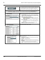
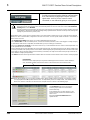
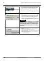
9960-TG2-REF1 Card Software Versions and this Manual
When applicable, Cobalt Digital Inc. provides for continual product
enhancements through software updates. As such, functions described in this
manual may pertain specifically to cards loaded with a particular software
build.
The Software Version of your card can be checked by viewing the Card Info
menu in DashBoard™. See Checking 9960-TG2-REF1 Card Information (p.
3-8) in Chapter 3, “Operating Instructions” for more information. You can
then check our website for the latest software version currently released for
the card as described below.
Note: Not all functionality described in this manual may appear on cards with initial
software versions.
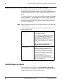
Check our website and proceed as follows if your card’s software does not
match the latest version:
Cobalt Reference Guides
From the Cobalt
®
web home page, go to Support>Reference Documents for
easy to use guides covering network remote control, card firmware updates,
example card processing UI setups and other topics.
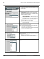
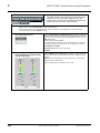
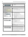
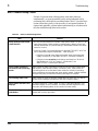
Card Software earlier than
latest version
Card is not loaded with the latest software. Not all
functions and/or specified performance described in
this manual may be available.
You can update your card with new Update software by
going to the Support>Firmware Downloads link at
www.cobaltdigital.com. Download “Firmware Update
Guide”, which provides simple instructions for
downloading the latest firmware for your card onto your
computer, and then uploading it to your card through
DashBoard™.
Software updates are field-installed without any
need to remove the card from its frame.
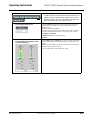
Card Software newer than
version in manual
A new manual is expediently released whenever a
card’s software is updated and specifications
and/or functionality have changed as compared to
an earlier version (a new manual is not necessarily
released if specifications and/or functionality have not
changed). A manual earlier than a card’s software
version may not completely or accurately describe all
functions available for your card.
If your card shows features not described in this
manual, you can check for the latest manual (if
applicable) and download it by going to the card’s web
page on www.cobaltdigital.com.

9960-TG2REF1-OM (V1.4) 9960-TG2-REF1 PRODUCT MANUAL 1-3
Introduction Manual Conventions
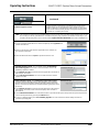
Manual Conventions
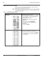
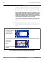
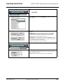
In this manual, display messages and connectors are shown using the exact
name shown on the 9960-TG2-REF1 itself. Examples are provided below.
• Card-edge display messages are shown like this:
• Connector names are shown like this: SDI IN A
In this manual, the terms below are applicable as follows:
• 9960-TG2-REF1 refers to the 9960-TG2-REF1 3G/HD/SD-SDI
Dual Test Signal Generator with Moving Box Active Signal
Indication and Bi-Level/Tri-Level Sync Out card.
• Frame refers to the HPF-9000, OG3-FR, 8321, or similar 20-slot
frame that houses Cobalt
®
or other cards.
• Device and/or Card refers to a Cobalt
®
or other card.
• System and/or Video System refers to the mix of interconnected
production and terminal equipment in which the 9960-TG2-REF1
and other cards operate.
• Functions and/or features that are available only as an option are
denoted in this manual like this:
BOOT

1 Manual Conventions
1-4 9960-TG2-REF1 PRODUCT MANUAL 9960-TG2REF1-OM (V1.4)
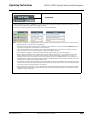
Warnings, Cautions, and Notes
Certain items in this manual are highlighted by special messages. The
definitions are provided below.
Warnings
Warning messages indicate a possible hazard which, if not avoided, could
result in personal injury or death.
Cautions
Caution messages indicate a problem or incorrect practice which, if not
avoided, could result in improper operation or damage to the product.
Notes
Notes provide supplemental information to the accompanying text. Notes
typically precede the text to which they apply.
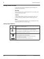
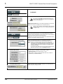
Labeling Symbol Definitions
Important note regarding product usage. Failure to observe may result in
unexpected or incorrect operation.
Electronic device or assembly is susceptible to damage from an ESD
event. Handle only using appropriate ESD prevention practices.
If ESD wrist strap is not available, handle card only by edges and avoid
contact with any connectors or components.
Symbol (WEEE 2002/96/EC)
For product disposal, ensure the following:
• Do not dispose of this product as unsorted municipal waste.
• Collect this product separately.
• Use collection and return systems available to you.

9960-TG2REF1-OM (V1.4) 9960-TG2-REF1 PRODUCT MANUAL 1-5
Introduction Safety and Regulatory Summary
Safety and Regulatory Summary
Warnings
Cautions
EMC Compliance Per Market
! WARNING !
To reduce risk of electric shock do not remove line voltage service barrier cover on frame
equipment containing an AC power supply. NO USER SERVICEABLE PARTS INSIDE.
REFER SERVICING TO QUALIFIED SERVICE PERSONNEL.
CAUTION
This device is intended for environmentally controlled use only in appropriate video
terminal equipment operating environments.
CAUTION
This product is intended to be a component product of an openGear® frame. Refer to the
openGear® frame Owner's Manual for important safety instructions regarding the proper
installation and safe operation of the frame as well as its component products.
CAUTION
Heat and power distribution requirements within a frame may dictate specific slot
placement of cards. Cards with many heat-producing components should be arranged to
avoid areas of excess heat build-up, particularly in frames using only convection cooling.
The 9960-TG2-REF1 has a moderate power dissipation (<18 W). As such, avoiding placing
the card adjacent to other cards with similar dissipation values if possible.
CAUTION
If required, make certain Rear I/O Module(s) is installed before installing the
9960-TG2-REF1 into the frame slot. Damage to card and/or Rear I/O Module can occur if
module installation is attempted with card already installed in slot.
CAUTION
If card resists fully engaging in rear I/O module mating connector, check for alignment and
proper insertion in slot tracks. Damage to card and/or rear I/O module may occur if
improper card insertion is attempted.
CAUTION
The 9960-TG2-REF1 FPGA is designed for a normal-range operating temperature around
85° C core temperature. Operation in severe conditions exceeding this limit for
non-sustained usage are within device operating safe parameters, and can be allowed by
setting this control to Disable. However, the disable (override) setting should be avoided
under normal conditions to ensure maximum card protection.
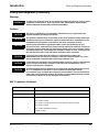
Market Regulatory Standard or Code
United States of America FCC "Code of Federal Regulations" Title 47 Part15, Subpart B, Class A
Canada ICES-003
International CISPR 24:2010
IEC 61000-4-2:2008
IEC 61000-4-3:2006 with A1:2007 and A2:2010 IEC 61000-4-4:2004
IEC 61000-4-6:2008
IEC 61000-6-3:2006 with A1:2010
CISPR 22:2008

1 9960-TG2-REF1 Functional Description
1-6 9960-TG2-REF1 PRODUCT MANUAL 9960-TG2REF1-OM (V1.4)
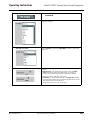
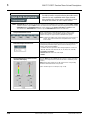
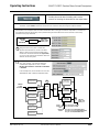
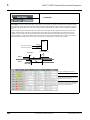
9960-TG2-REF1 Functional Description
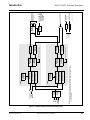
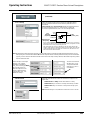
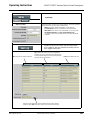
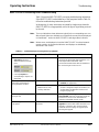
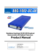
Figure 1-1 shows a functional block diagram of the 9960-TG2-REF1. The
9960-TG2-REF1 provides comprehensive test signal packages to test and
validate downstream baseband SDI systems. Two independent generator
blocks (
TG1, TG2) can be set to offer dual test packages which can be
simultaneously outputted or selectively fed to a single downstream path via a
2x4 output crosspoint.
In addition to numerous high-quality industry-standard test patterns and user
static raster import, the 9960-TG2-REF1 also allows custom DID/SDID
packages to be added to test non-conventional or custom processing.
The 9960-TG2-REF1 also provides AES and analog audio test tones (both
using 24-bit data), and also provides waveform-based test data over its CVBS
video output. A moving-box insertion can be enabled to serve as a dynamic
raster confidence check. The 9960-TG2-REF1 can use either of two frame
references to provide an output that’s synchronous with house ref, or use its
internal ref timing to generate its own ref. An analog video output offers SD
black burst or HD bi-level/tri-level reference output, line 21 CEA 608
closed-captioning and VITC waveform TC outputs. Audio LTC test
sequences are available over embedded, AES, and analog audio as well as via
an RS-485 serial port.
9960-TG2-REF1 Outputs
The 9960-TG2-REF1 provides the following outputs:
• 3G/HD/SD-SDI IN (User Import) – 3G/HD/SD-SDI input allows import
(frame capture) of SDI input. This input can be routed either or both
TSG
TG1 or TG2.
• 3G/HD/SD-SDI TG 1/2 OUT (1-4) – four 3G/HD/SD-SDI outputs. Each
output can be independently set to route the TSG
TG1 or TG2 signal as
its output.
• REF/CVBS OUT – CVBS coaxial analog video output; provides
bi-level/tri-level ref, VITC waveform timecode, and CEA 608 line 21
closed-captioning data when an SD TSG output is selected.
• AES OUT – Multiple AES-3id ports which provide AES audio test
signals such as tones or audio LTC. These outputs are
timing-referenced to the selected TSG
TG1 or TG2 signal; each AES
test source output can be independently referenced to either of the
TG1 or TG2.
• AN-AUD OUT – Four balanced analog audio de-embed test signal
outputs which provide configurable tone outputs.
• RS-485 LTC OUT – RS-485 LTC timecode output. This output is
correlated to either of the selected
TG1 or TG2 generator blocks.

9960-TG2REF1-OM (V1.4) 9960-TG2-REF1 PRODUCT MANUAL 1-7
Introduction 9960-TG2-REF1 Functional Description
Figure 1-1 9960-TG2-REF1 Functional Block Diagram
Output
Crosspoint
9960TG2REFBD V1.0LB118
3G/HD/SD-SDI
TG 1/2 OUT
Video
DAC
REF/CVBS OUT
- Black Burst and
HD Tri-Lev Ref
- VITC WVFM
- Line 21 CC
1
2
3
4
AES Tx
Audio DAC
AES OUT
(16-Ch)
AN-AUD OUT
Note: Signal connections shown depicts full input/output capability. Practical input/
output signal availability is determined by rear I/O module used. Refer to text for
more information.
From TG 1/2
Audio
De-Embed
RS-485 LTC OUT
DID/SDID
Authoring
Pattern Gen
Moving-Box Gen
Graphics Burn-In
Audio Gen/
Control
Output
Routing
Serialize
RS-485 LTC
Encode
TG1 Audio De-Embed
Ref Lock/
Select
Delay
Offset
Ref 1
Ref 2
Internal
CLK Ref
DID/SDID
Authoring
Pattern Gen
Moving-Box Gen
Graphics Burn-In
Audio Gen/
Control
Output
Routing
Serialize
RS-485 LTC
Encode
TG2 Audio De-Embed
TG1
TG2
User SDI
Import
Capture

1 9960-TG2-REF1 Functional Description
1-8 9960-TG2-REF1 PRODUCT MANUAL 9960-TG2REF1-OM (V1.4)
Video TSG Description
The 9960-TG2-REF1 features dual independent video TSG blocks, each
capable of independent rasters, output format, and embedded ancillary data.
Ref Lock Function
This function allows either of the TG1 or TG2 generators to receive ref lock
using either one of two external
FRAME REF IN (1,2) reference signals
distributed with the card frame, or a card internal ref lock source. Selectable
failover allows alternate reference selection should the initial reference source
become unavailable or invalid. This function also allows independent delay
offsets for the
TG1 and TG2 generators to be added or removed relative to the
selected ref source.
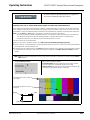
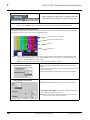
Test Pattern Generator Function
Independent internal test pattern generators provides a selection of various
standard patterns such as color bars, sweep patterns, and other technical
patterns. A user-captured TSG selection allows a full video frame to captured
and stored, available then as one of the pattern choices.
Character/Image Burn-in Functions
User text and timecode (as selected using the timecode function) can be
burned into the output video. Burn-in attributes such as size, position,
background, color, and opacity are user-configurable. Two discrete character
burn strings can be inserted on output video, with each string inserted as static
text and/or insert only upon LOS. A moving-box insertion can be enabled to
serve as a dynamic raster confidence check.
Logo Insertion Function
This function provides for a graphic insertion onto the SDI processed output
raster. The function allows for uploading a .png image graphic file to the card/
device memory. (png files are converted to a .bin format using a web tool
before uploading to the host card/device; this is described in the setup/
operating instructions in Chapter 3.) Insertion enable/disable is then manually
controlled using DashBoard.
ANC Generator Description
Timecode Generators
This function embeds packet-based timecode strings on the output video.
Independent timecode insertion is provided for the
TG1 or TG2 generators. A
user entry dialog allows a running count (including fields for interlaced
formats) in ATC_LTC and/or ATC_VITC for 3G/HD, and ATC_VITC or
VITC waveform (with selectable odd/even field line number control) for SD
SDI or CVBS inputs. Waveform VITC timecode can also be extracted from a
reference input and used as the output timecode value.
LTC timecode can also be outputted over embedded or discrete AES or
analog audio, and can be outputted as RS-485.

9960-TG2REF1-OM (V1.4) 9960-TG2-REF1 PRODUCT MANUAL 1-9
Introduction 9960-TG2-REF1 Functional Description
AFD Generators
This function embeds user-entered static AFD code strings on the output SDI
video. Independent strings and formatting can be inserted for the
TG1 or TG2
generators. The function also allows the selection/changing of the AFD code
and ancillary data line number for the outputted AFD code.
SCTE104 Insertion
SCTE104 functionality provides generation and insertion of SCTE 104
messages into baseband SDI. Message send can be triggered from automation
GPI or other event action modes. The function can also execute card actions
based on SCTE 104 messages received by the card, as well as send triggered
SCTE 104 packets to other downstream systems.
The user interface is based on common SCTE 104 operations: Splice Start
Normal, Splice Start Intermediate, Splice End Normal, Splice End
Intermediate, and Splice Cancel (splice_request_data variants), offering full
control of splice start, end, and cancel as well as pre-roll and break duration
offsets.
CEA 608 Closed Captioning Insertion
Closed Captioning generator provides generation and insertion of CEA 608
Ch 1 -Ch 4 test messages to be inserted into VBI space for testing
downstream systems ability to process and retain CEA closed captioning data.
User text strings can be entered, and then set for display style (Paint On, Pop
On, or Roll Up) messages.
Video Output Crosspoint
A four-output video matrix crosspoint allows independently applying either
of the
TG1 or TG2 generator SDI outputs to any of the four card discrete
coaxial outputs (
SDI OUT 1 thru SDI OUT 4). For an SD output, a CVBS
coaxial output is available as a processed video output.
De-Embed Audio Processor Description
The audio processor operates as an internal audio router that selects
embedded audio channel content from either
TG1 or TG2 for use as discrete
audio channels over up to 16 AES channels and/or four balanced analog
output channels. Any of the 32 total
TG1 and TG2 embedded channels can be
outputted over any of AES or analog audio output channels.

1 9960-TG2-REF1 Functional Description
1-10 9960-TG2-REF1 PRODUCT MANUAL 9960-TG2REF1-OM (V1.4)
Control and Data Input/Output Interfaces
GPI Interface
Two independent ground-closure sensing GPI inputs (GPI 1 and GPI 2; each
sharing common ground connection as chassis potential) are available.
Associated with each GPI user control is a selection of one of 32 user-defined
card presets in which GPI activation invokes a card control preset. Because
the GPI closure invokes a user-defined preset, the resulting setup is highly
flexible and totally user-defined. Invoking a user preset to effect a change
involves card setup communication limited only to the items being changed;
the card remains on-line during the setup, and the called preset is rapidly
applied.
GPI triggering can be user selected to consider the activity on discrete GPI
ports, or combinations of logic states considering both GPI inputs. This
flexibility allows multistage, progressive actions to be invoked if desired.
Indication is provided showing whenever a GPI input has been invoked.
GPO Interface
Two independent phototransistor non-referenced (floating) contact pairs
(
GPO 1/1 and GPO 2/2) are available. A GPO can be invoked by setting a GPO
to be enabled when a card preset is in turn applied (i.e., when a preset is
invoked (either manually or via event-based loading), the GPO is
correspondingly also activated.
Serial (COMM) Ports
The 9960-TG2-REF1 is equipped with two, 3-wire serial ports (COM 1 - Serial
Port 1, COM 2 - Serial Port 2). The ports provide for RS-485 LTC I/O. Either
port can be configured as RS-232 Tx/Rx or RS-485 non-duplexed Tx or Rx.

9960-TG2REF1-OM (V1.4) 9960-TG2-REF1 PRODUCT MANUAL 1-11
Introduction 9960-TG2-REF1 Functional Description
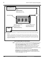
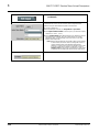
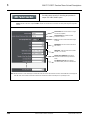
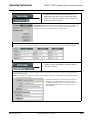
User Control Interface
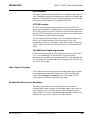
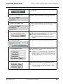
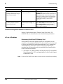
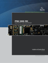
Figure 1-2 shows the user control interface functions for the
9960-TG2-REF1. These functions are individually described below.
Note: All user control interfaces described here are cross-compatible and can oper-
ate together as desired. Where applicable, any control setting change made
using a particular user interface is reflected on any other connected interface.
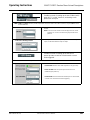
• DashBoard™ User Interface – Using DashBoard™, the
9960-TG2-REF1 and other cards installed in openGear®
1
frames can
be controlled from a computer and monitor.
DashBoard™ allows users to view all frames on a network with
control and monitoring for all populated slots inside a frame. This
simplifies the setup and use of numerous modules in a large
installation and offers the ability to centralize monitoring. Cards
define their controllable parameters to DashBoard™, so the control
interface is always up to date.
The DashBoard™ software can be downloaded from the Cobalt
Digital Inc. website: www.cobaltdigital.com
(enter “DashBoard” in
the search window). The DashBoard™ user interface is described in
Chapter 3,“Operating Instructions”.
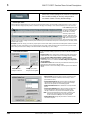
• Cobalt
®
OGCP-9000 and OGCP-9000/CC Remote Control
Panels – The OGCP-9000 and OGCP-9000/CC Remote Control
Panels conveniently and intuitively provide parameter monitor and
control of the 9960-TG2-REF1 and other video and audio processing
terminal equipment meeting the open-architecture Cobalt
®
cards for
openGear™ standard.
In addition to circumventing the need for a computer to monitor and
control signal processing cards, the Control Panels allow quick and
intuitive access to hundreds of cards in a facility, and can monitor and
allow adjustment of multiple parameters at one time.
The Remote Control Panels are totally compatible with the
openGear™ control software DashBoard™; any changes made with
either system are reflected on the other. The Remote Control Panel
user interface is described in Chapter 3,“Operating Instructions”.
1. openGear® is a registered trademark of Ross Video Limited. DashBoard™ is a trademark of Ross
Video Limited.

1 9960-TG2-REF1 Functional Description
1-12 9960-TG2-REF1 PRODUCT MANUAL 9960-TG2REF1-OM (V1.4)
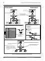
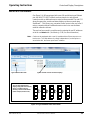
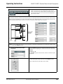
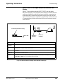
Figure 1-2 9960-TG2-REF1 User Control Interface
Note: If network remote control is to be used for the frame and the frame has not yet
been set up for remote control, Cobalt
®
reference guide Remote Control
User Guide (PN 9000RCS-RM) provides thorough information and
step-by-step instructions for setting up network remote control of Cobalt
®
cards using DashBoard™. (Cobalt
®
OGCP-9000 and OGCP-9000/CC
Remote Control Panel product manuals have complete instructions for setting
up remote control using a Remote Control Panel.)
Download a copy of this guide by clicking on the Support>Reference
Documents link at www.cobaltdigital.com and then select DashBoard
Remote Control Setup Guide as a download, or contact Cobalt
®
as listed in
Contact Cobalt Digital Inc. (p. 1-15).
Computer
with NIC
OGCP-9000 Control Panel
or
OGCP-9000/CC Control Panel
20-Slot Frame with Network Controller Card
LAN
9960-TG2-REF1 Card
In conjunction with a frame equipped
with a Network Controller Card,
9960-TG2-REF1 card can be
remotely controlled over a LAN
Remote Control Panel
Using the Control Panel,
9960-TG2-REF1 card can be
remotely controlled over a LAN
DashBoard™ Remote Control
Using a computer with
DashBoard™ installed,
9960-TG2-REF1 card can be
remotely controlled over a LAN
Note: • To communicate with DashBoard™ or a Remote Control Panel, the frame must have a network controller card installed in
the frame.
• DashBoard™ and the Remote Control Panels provide network control of the 9960-TG2-REF1 as shown. The value
displayed at any time on the card, or via DashBoard™ or a Control Panel is the actual value as set on the card, with the
current value displayed being the actual value as effected by the card. Parameter changes made by any of these means
are universally accepted by the card (for example, a change made using the DashBoard™ controls will change the setting
displayed on a Control Panel).

9960-TG2REF1-OM (V1.4) 9960-TG2-REF1 PRODUCT MANUAL 1-13
Introduction Technical Specifications
9960-TG2-REF1 Rear I/O Modules
The 9960-TG2-REF1 physically interfaces to system video connections at the
rear of its frame using a Rear I/O Module. All inputs and outputs shown in the
9960-TG2-REF1 Functional Block Diagram (Figure 1-1) enter and exit the
card via the card edge backplane connector. The Rear I/O Module breaks out
the 9960-TG2-REF1 card edge connections to BNC and other connectors that
interface with other components and systems in the signal chain.
The full assortment of 9960-TG2-REF1 Rear I/O Modules is shown and
described in 9960-TG2-REF1 Rear I/O Modules (p. 2-4) in Chapter 2,
“Installation and Setup”.
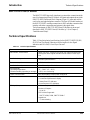
Technical Specifications
Table 1-1 lists the technical specifications for the 9960-TG2-REF1 3G/HD/
SD-SDI Dual Test Signal Generator with Moving Box Active Signal
Indication and Bi-Level/Tri-Level Sync Out card.
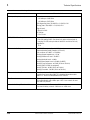
Table 1-1 Technical Specifications
Item Characteristic
Part number, nomenclature 9960-TG2-REF1 3G/HD/SD-SDI Dual Test Signal Generator with
Moving Box Active Signal Indication and Bi-Level/Tri-Level Sync
Out
Installation/usage environment Intended for installation and usage in frame meeting openGear™
modular system definition
Power consumption < 18 Watts maximum
Installation Density Up to 20 cards per 20-slot frame
Environmental:
Operating temperature:
Relative humidity (operating or storage):
32° – 104° F (0° – 40° C)
< 95%, non-condensing
Frame communication 10/100/1000 Mbps Ethernet with Auto-MDIX
Indicators Card edge display and indicators as follows:
• 4-character alphanumeric display
• Status/Error LED indicator
• Input Presence LED indicators
SDI Input/Outputs Number of Inputs: (1) 75Ω BNC
Number of Outputs:
Up to (4)
SDI Formats Supported:
SMPTE 424M, 292M, SMPTE 259M-C
Impedance:
75 Ω terminating

1 Technical Specifications
1-14 9960-TG2-REF1 PRODUCT MANUAL 9960-TG2REF1-OM (V1.4)
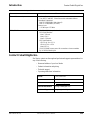
SDI Input/Outputs (cont.) Return Loss:
> 15 dB up to 1.485 GHz
> 10 dB up to 2.970 GHz
SDI Alignment Jitter: 3G/HD/SD: < 0.3/0.2/0.2 UI
Timing Jitter: 3G/HD/SD: < 2.0/1.0/0.2 UI
Signal Level:
800 mV ± 10%
DC Offset:
0 V ± 50 mV
REF/CVBS Video Output Number of Outputs:
One SD analog CVBS (functional only when selected path is
carrying SD-SDI; also provides bi-level SD and tri-lev HD ref)
Impedance:
75 Ω
Discrete Audio Outputs AES-3id 75Ω outputs (8 pair (16-Ch) max)
Balanced analog audio outputs (4-Ch max)
(I/O conforms to 0 dBFS = +24 dBu)
Analog Output Impedance: < 50 Ω
Analog Reference Level: -20 dBFS
Analog Nominal Level: +4 dBu
Analog Max Output Level: +24 dBu (0 dBFS)
Analog Freq. Response: ±0.2 dB (20 Hz to 20 kHz)
Analog SNR: 115 dB (A weighted)
Analog THD+N: -96 dB (20 Hz to 10 kHz)
Analog Crosstalk: -106 dB (20 Hz to 20 kHz)
Timecode Insertion/Burn-In Burn-in and embedded video output timecode selected via user
controls from input video SMPTE embedded timecode and/or
audio LTC. Burn-in enable/disable user controls.
Text Burn-In (2) independent strings supported. Independent insertions controls
for enable/disable and enable upon LOS. User controls for text
size and H/V position.
User Audio Delay Offset from Video Bulk delay control: -33 msec to +3000 msec
Per-channel delay controls: -800 msec to +800 msec
Table 1-1 Technical Specifications — continued
Item Characteristic

9960-TG2REF1-OM (V1.4) 9960-TG2-REF1 PRODUCT MANUAL 1-15
Introduction Contact Cobalt Digital Inc.
Contact Cobalt Digital Inc.
Feel free to contact our thorough and professional support representatives for
any of the following:
• Name and address of your local dealer
• Product information and pricing
• Technical support
• Upcoming trade show information
Frame Reference Input Number of Inputs:
Two, REF 1 and REF 2 from frame with selectable failover
Standards Supported:
SMPTE 170M/318M (“black burst”)
SMPTE 274M/296M (“tri-color”)
Return Loss:
> 35 dB up to 5.75 MHz
GPIO/COMM (2) GPI; (2) GPO; opto-isolated
GPO Specifications:
Max I: 120 mA
Max V: 30 V
Max P: 120 mW
GPI Specifications:
GPI LO @ Vin < 1.5 V
GPI HI @ Vin > 2.3 V
Max Vin: 9 V
(2) RS-232/485 comm ports. All connections via rear module
RJ-45 GPIO/COMM jack.
Table 1-1 Technical Specifications — continued
Item Characteristic
Phone: (217) 344-1243
Fax: (217) 344-1245
Web: www.cobaltdigital.com
General Information: info@cobaltdigital.com
Technical Support: support@cobaltdigital.com

1 Warranty and Service Information
1-16 9960-TG2-REF1 PRODUCT MANUAL 9960-TG2REF1-OM (V1.4)
Warranty and Service Information
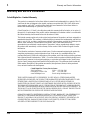
Cobalt Digital Inc. Limited Warranty
This product is warranted to be free from defects in material and workmanship for a period of five (5)
years from the date of shipment to the original purchaser, except that 4000, 5000, 6000, 8000 series
power supplies, and Dolby
®
modules (where applicable) are warranted to be free from defects in
material and workmanship for a period of one (1) year.
Cobalt Digital Inc.'s (“Cobalt”) sole obligation under this warranty shall be limited to, at its option, (i)
the repair or (ii) replacement of the product, and the determination of whether a defect is covered under
this limited warranty shall be made at the sole discretion of Cobalt.
This limited warranty applies only to the original end-purchaser of the product, and is not assignable or
transferrable therefrom. This warranty is limited to defects in material and workmanship, and shall not
apply to acts of God, accidents, or negligence on behalf of the purchaser, and shall be voided upon the
misuse, abuse, alteration, or modification of the product. Only Cobalt authorized factory
representatives are authorized to make repairs to the product, and any unauthorized attempt to repair
this product shall immediately void the warranty. Please contact Cobalt Technical Support for more
information.
To facilitate the resolution of warranty related issues, Cobalt recommends registering the product by
completing and returning a product registration form. In the event of a warrantable defect, the
purchaser shall notify Cobalt with a description of the problem, and Cobalt shall provide the purchaser
with a Return Material Authorization (“RMA”). For return, defective products should be double boxed,
and sufficiently protected, in the original packaging, or equivalent, and shipped to the Cobalt Factory
Service Center, postage prepaid and insured for the purchase price. The purchaser should include the
RMA number, description of the problem encountered, date purchased, name of dealer purchased
from, and serial number with the shipment.
Cobalt Digital Inc. Factory Service Center
2506 Galen Drive Office: (217) 344-1243
Champaign, IL 61821 USA Fax: (217) 344-1245
www.cobaltdigital.com Email: info@cobaltdigital.com
THIS LIMITED WARRANTY IS EXPRESSLY IN LIEU OF ALL OTHER WARRANTIES
EXPRESSED OR IMPLIED, INCLUDING THE WARRANTIES OF MERCHANTABILITY AND
FITNESS FOR A PARTICULAR PURPOSE AND OF ALL OTHER OBLIGATIONS OR
LIABILITIES ON COBALT'S PART. ANY SOFTWARE PROVIDED WITH, OR FOR USE WITH,
THE PRODUCT IS PROVIDED “AS IS.” THE BUYER OF THE PRODUCT ACKNOWLEDGES
THAT NO OTHER REPRESENTATIONS WERE MADE OR RELIED UPON WITH RESPECT TO
THE QUALITY AND FUNCTION OF THE GOODS HEREIN SOLD. COBALT PRODUCTS ARE
NOT AUTHORIZED FOR USE IN LIFE SUPPORT APPLICATIONS.
COBALT'S LIABILITY, WHETHER IN CONTRACT, TORT, WARRANTY, OR OTHERWISE, IS
LIMITED TO THE REPAIR OR REPLACEMENT, AT ITS OPTION, OF ANY DEFECTIVE
PRODUCT, AND SHALL IN NO EVENT INCLUDE SPECIAL, INDIRECT, INCIDENTAL, OR
CONSEQUENTIAL DAMAGES (INCLUDING LOST PROFITS), EVEN IF IT HAS BEEN
ADVISED OF THE POSSIBILITY OF SUCH DAMAGES.
Page is loading ...
Page is loading ...
Page is loading ...
Page is loading ...
Page is loading ...
Page is loading ...
Page is loading ...
Page is loading ...
Page is loading ...
Page is loading ...
Page is loading ...
Page is loading ...
Page is loading ...
Page is loading ...
Page is loading ...
Page is loading ...
Page is loading ...
Page is loading ...
Page is loading ...
Page is loading ...
Page is loading ...
Page is loading ...
Page is loading ...
Page is loading ...
Page is loading ...
Page is loading ...
Page is loading ...
Page is loading ...
Page is loading ...
Page is loading ...
Page is loading ...
Page is loading ...
Page is loading ...
Page is loading ...
Page is loading ...
Page is loading ...
Page is loading ...
Page is loading ...
Page is loading ...
Page is loading ...
Page is loading ...
Page is loading ...
Page is loading ...
Page is loading ...
Page is loading ...
Page is loading ...
Page is loading ...
Page is loading ...
Page is loading ...
Page is loading ...
Page is loading ...
Page is loading ...
Page is loading ...
Page is loading ...
Page is loading ...
Page is loading ...
Page is loading ...
Page is loading ...
Page is loading ...
Page is loading ...
Page is loading ...
Page is loading ...
Page is loading ...
Page is loading ...
Page is loading ...
Page is loading ...
Page is loading ...
Page is loading ...
-
 1
1
-
 2
2
-
 3
3
-
 4
4
-
 5
5
-
 6
6
-
 7
7
-
 8
8
-
 9
9
-
 10
10
-
 11
11
-
 12
12
-
 13
13
-
 14
14
-
 15
15
-
 16
16
-
 17
17
-
 18
18
-
 19
19
-
 20
20
-
 21
21
-
 22
22
-
 23
23
-
 24
24
-
 25
25
-
 26
26
-
 27
27
-
 28
28
-
 29
29
-
 30
30
-
 31
31
-
 32
32
-
 33
33
-
 34
34
-
 35
35
-
 36
36
-
 37
37
-
 38
38
-
 39
39
-
 40
40
-
 41
41
-
 42
42
-
 43
43
-
 44
44
-
 45
45
-
 46
46
-
 47
47
-
 48
48
-
 49
49
-
 50
50
-
 51
51
-
 52
52
-
 53
53
-
 54
54
-
 55
55
-
 56
56
-
 57
57
-
 58
58
-
 59
59
-
 60
60
-
 61
61
-
 62
62
-
 63
63
-
 64
64
-
 65
65
-
 66
66
-
 67
67
-
 68
68
-
 69
69
-
 70
70
-
 71
71
-
 72
72
-
 73
73
-
 74
74
-
 75
75
-
 76
76
-
 77
77
-
 78
78
-
 79
79
-
 80
80
-
 81
81
-
 82
82
-
 83
83
-
 84
84
-
 85
85
-
 86
86
-
 87
87
-
 88
88


Cobalt Digital 9960-TG2-REF1 3G/HD/SD-SDI Dual Test Signal Generator User manual
- Type
- User manual
Ask a question and I''ll find the answer in the document
Finding information in a document is now easier with AI
Related papers
-
Cobalt Digital %2bAMx Audio Mixer Software Operating instructions
-
-
-
-
-
 Cobalt Digital Inc BBG-1002-DC-4K User manual
-
-
 Cobalt Digital Inc BBG-1078-ANC-MON 3G/HD/SD-SDI Standalone Ancillary Data Monitoring Probe User manual
-
-


Other documents
-
Bodyworx Colorado 300 Owner's manual
-
IVIEW 769TPCII Operating instructions
-
 Cobalt Digital Inc BBG-1034-AUD-PRO User manual
-
Tektronix SPG700 User manual
-
-
Wohler HDM-215-3G-TT Owner's manual
-
TOA 9000 User manual
-
-
Clear-Com V-Series AES-3 User manual
-
 Algolith FRS-1002-MD-LG-PA User manual

