Page is loading ...

THANK YOU
We appreciate the trust and confidence you have placed in ETi through the purchase of this LED light. We strive to continually create quality
products designed to enhance your home. Visit us online to see our full line of products available for your home improvement needs.
Thank you for choosing ETi!
Part # COL-11-802-MV-O-W
COL-11-802-MV-O-B
COL-8-830-MV-O-W
COL-8-830-MV-O-B
Model # 50402111
50402112
50404111
50404112
USE AND CARE GUIDE
SHOREBREAKER™ OUTDOOR LIGHT
Questions, problems, missing parts?
Call ETiSSL Customer Service
8 a.m. - 5 p.m., CST, Monday - Friday
1-855-ETI-SSLI (1-855-384-7754)
www.ETiSSL.com

2
3 WWW.ETiSSL.COM
Please contact 1-855-384-7754 for further assistance.
Table of Contents
Table of Contents ...................................2
Safety Information ..................................2
Warranty ..........................................2
Pre-Installation .....................................3
Planning Installation ...............................3
Tools Required ....................................3
Package Contents .................................3
Hardware Included .................................4
Additional Parts Available to Purchase .................4
Installation ........................................4
Adding a Decorative Guard ...........................6
Adjusting the Color Temperature of the Light .............7
Care and Cleaning ..................................8
Troubleshooting ....................................8
Safety Information
WARNING: Carefully read and understand the information
given in this manual before beginning the assembly and
installation. Failure to do so so could lead to electric shock,
fire, or other injuries which could be hazardous or even fatal.
WARNING: Ensure the electricity to the wires you are
working on is shut off. Either remove the fuse or turn off the
circuit breaker
.
WARNING: This luminaire must be installed in accordance
with NEC or your local electrical code.
NOTICE: Do not use this fixture with a dimmer switch.
NOTICE: This equipment has been tested and found to comply with the
limits for a Class B digital device, pursuant to Part 15 of the FCC Rules.
These limits are designed to provide reasonable protection against harmful
interference in a residential installation.
This equipment generates, uses and can radiate radio frequency energy
and, if not installed and used in accordance with the instructions, may
cause harmful interference to radio communications. However, there is
no guarantee that interference will not occur in a particular installation.
If this equipment does cause harmful interference to radio or television
reception, which can be determined by turning the equipment off and on,
the user is encouraged to try to correct the interference by one or more of
the following measures:
□ Reorient or relocate the receiving antenna.
□ Increase the separation between the equipment and the receiver.
□ Connect the equipment into an outlet on a circuit different from that to
which the receiver is connected.
□ Consult the dealer or an experienced radio/TV technician for help.
WARNING: Changes or modifications not expressly approved
by the party responsible for compliance could void the user’s
authority to operate the equipment.
Warranty
This product is warranted for a period of 5 years from the date of original purchase against defects in materials and workmanship. If this
product should fail to operate due to defects in material or workmanship within 60 months of purchase, see www.ETiSSL.com for details.
This product will be repaired or replaced, at ETi’s option. This warranty is expressly limited to repair or replacement of product, and liability
for direct, incidental, or consequential damages is hereby expressly excluded. Some states do not allow exclusions of direct, incidental or
consequential damages, so the above limitation of exclusion may not apply to you. This warranty gives the consumer specific legal rights,
which vary from state to state. WARRANTY IS VOID IF PRODUCT IS NOT USED FOR THE PURPOSE WHICH THIS PRODUCT IS MANUFACTURED.
A CB
Pre-Installation
PLANNING INSTALLATION
Before beginning assembly, installation or operation of product, make sure all parts are present. Compare parts with the package
contents list. If any part is missing or damaged, do not attempt to assemble, install or operate the product. Contact customer service for
replacement parts.
NOTE: Keep your receipt and these instructions for proof of purchase.
If you are unfamiliar with electrical installations, we recommend you contact a qualified electrician to do the installation.
TOOLS REQUIRED
Wire
Strippers
Safety
Goggles
Ladder Gloves
Flathead
Screwdriver
Phillips
Screwdriver
Electrical
Tape
Wire
Cutters
Silicone
Sealant
PACKAGE CONTENTS
Part Description Quantity
A Lens Cover 1
B Light Board 1
C Fixture Housing 1
HARDWARE INCLUDED
NOTE: Hardware not shown to actual size.
Part Description Quantity
AA Hex Nut 1
BB Wire Connector 3
CC Electrical Box Screw 2
DD Threaded Nipple 1
EE Mounting Bracket 1
AA BB CC
DD EE

4
5 WWW.ETiSSL.COM
Please contact 1-855-384-7754 for further assistance.
Pre-Installation (continued) Installation (continued)
ADDITIONAL PARTS AVAILABLE TO PURCHASE
NOTE: Separate parts not shown to actual size. Contact ETi for
more information and to purchase.
Part Description Quantity Model # Color
F Decorative Guard 1
90600508
90600507
White
Black
G Decorative Guard 1
90600504
90600503
White
Black
1
Removing the lens cover from the
fixture housing
□ Remove the lens cover (A) by loosening the 4 screws
attaching it to the fixture housing (C). Set the screws
aside until ready to reassemble the fixture.
□ Remove the fixture screw that attaches the light
board (B) to the fixture housing (C) and set aside until
ready to reassemble the fixture.
□ Detach the light board (B) from the fixture housing (C).
2
Feeding the wires through the fixture
housing
□ Feed the wires from the light board (B) through the hex
nut (AA) and then through the fixture housing (C).
□ Insert the threaded nipple (DD) through the the center hole
of the mounting bracket (EE).
□ Thread the wires through the threaded nipple (DD) and the
mounting bracket (EE).
3
Making the electrical connections
□ Connect the hot and neutral (black and white) wires from the light
board (B) and fixture housing (C) to the same color wires from the
electrical box.
□ Connect the green wire from the light board (B) and fixture
housing (C) to the ground wire from the electrical box.
□ Cover the wire connections using the wire connectors (BB).
□ Wrap the wire connectors (BB) with electrical tape for a more
secure connection.
□ Position the wires back inside the electrical box.
4
Securing the mounting bracket
□ Place the mounting bracket (EE) over the
electrical box.
□ Use the electrical box screws (CC) to secure the
mounting bracket (EE) to the electrical box.
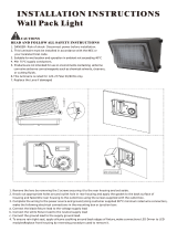
Installation
WARNING: RISK OF ELECTRIC SHOCK. Ensure the electricity to the wires you are working on is shut off. Either remove the fuse or turn off the
circuit breaker before removing the existing light fixture or installing the new one.
With power disconnected to the electrical box, remove the existing fixture. Make a sketch of how the current fixture is wired (by wire color)
or mark the wires with masking tape and a pencil so you will know how to properly reconnect the wires to the new LED light fixture.
Lens
Screws
A
B
C
DD
AA
5
Mounting the fixture housing
□ Position the fixture housing (C) onto the
threaded nipple (DD).
□ Tighten the hex nut (AA) onto the threaded
nipple (DD) until the fixture housing (C) is
securely attached to the mounting surface.
6
Securing the light board to the fixture
housing
□ Place the light board (B) onto the fixture housing (C), aligning the
screw holes with those in the fixture housing (C).
□ Use the fixture screw that was previously set aside to secure the
light board (B) to the fixture housing (C).
C
B
Fixture
Screw
Fixture
Screw
EE
DD
AA
EE
BB
B C
EE
AA
B C
CC
CB
DD
AA
C
F
G

3000K 4000K 5000K
6
7 WWW.ETiSSL.COM
Please contact 1-855-384-7754 for further assistance.
Installation (continued)
Adding a Decorative Guard
7
Securing the lens cover
□ Place the lens cover (A) over the light board (B) and
gently tighten the screws to firmly secure the lens
cover (A) to the fixture housing (C).
□ Restore power at the electrical panel.
□ Turn on the light switch to activate the fixture.
8
Sealing the fixture housing
□ Apply silicone caulk (not provided) around the back edges
of the fixture housing (C) to ensure a watertight seal.
1
Selecting a decorative guard
□ Choose a decorative guard (not included) for the fixture, if desired.
Part Description Model # Color
F Decorative Guard
90600508
90600507
White
Black
G Decorative Guard
90600504
90600503
White
Black
NOTE: Separate parts not shown to actual size. Contact ETi for
more information and to purchase.
A
C
Lens Cover
Screws
Adding a Decorative Guard (continued)
2
Preparing to install a
decorative guard
□ Remove the screws from the lens
cover (A).
3
Securing the decorative guard to the fixture
□ Place the decorative guard (not included) over the lens cover (A).
□ Secure the decorative guard with the screws removed from the lens
cover (A).
F
G
B
Adjusting the Color Temperature of the Light
Ordering # 50402111/Part # COL-11-802-MV-O-W and Ordering #
50402112/Part # COL-11-802-MV-O-B
This LED light fixture allows you to customize the color
temperature of the light using three settings: soft white, cool
white, or daylight.
□ Choose your favorite correlated color temperature (CCT)
from three options: 3000K Soft White, 4000K Cool White, or
5000K Daylight.
□ Move the toggle switch on the light board (B) to make your
selection before attaching the lens cover (A) to the fixture
plate (C).
NOTICE: The factory setting for the correlated color
temperature (CCT) is 3000K, which is the warmest white light.
A
A
A
A
G
F
A
C

8
Questions, problems, missing parts?
Call ETiSSL Customer Service
8 a.m. - 5 p.m., CST, Monday - Friday
1-855-ETI-SSLI (1-855-384-7754)
www.ETiSSL.com
Retain this manual for future use.
MERCI
Nous apprécions la confiance que vous avez accordé à la ETi Solid State Lighting, Inc. en achetant ce luminaire à DEL.
Consultez notre gamme complète de produits en ligne. Nous vous remercions d’avoir choisi ETi!
N° de pièce COL-11-802-MV-O-W
COL-11-802-MV-O-B
COL-8-830-MV-O-W
COL-8-830-MV-O-B
N° de certification 50402111
50402112
50404111
50404112
Care and Cleaning
CAUTION: Before attempting to clean the fixture, disconnect the power to the fixture by turning the breaker off or removing the fuse from the
fuse box.
□ Clean the fixture with a soft, dry cloth.
□ Do not use cleaners with chemicals, solvents, or harsh abrasives.
□ Do not use liquid cleaner on the LEDs, LED driver, or wiring inside the light fixture.
Troubleshooting
WARNING: Before doing any work on the fixture, disconnect power to the light fixture.
Minor problems often can be fixed without the help of an electrician.
Problem Possible Cause Solution
The fixture will not light. The power is off. Ensure the power supply is on.
The circuit breaker is off. Ensure the circuit breaker is in the on position.
There is a bad connection. Check to ensure proper wire connections are made.
Contact a qualified electrician.
There is a defective switch. Contact a qualified electrician.
The fuse blows or the circuit breaker
trips when the light is turned on.
The wires are crossed or the power
wire is grounding out.
Check the wire connections.
Contact a qualified electrician or call customer
service 1-855-384-7754.
GUIDE D’UTILISATION ET D’ENTRETIEN
LAMPE D’EXTÉRIEUR SHOREBREAKER
MC
Questions, difficultés, pièces manquantes?
Téléphonez au service à la clientèle de ETiSSL
8 h - 17 h, HNC, du lundi au vendredi.
1-855-ETI-SSLI (1-855-384-7754)
www.ETiSSL.com
/