Page is loading ...

G-MAX
TM
Flex ATX Series Us er’s M anual
P. E1
Co pyr igh t No ti ce
Copyright 2002 Gigabyt e Technology.
All Rights Reserved. No part of this doc umentation, including but not limited t o the products
and software desc ribed in it, may be reproduced, trans mitted, transcribed, stored in a
retrieval system, or translated into any language, in any form or by any means without the
express written permission of Gigabyt e Technology.
Trademarks
Products and corporate nam es appearing in this manual m ay be registered trademarks or
copyrights of their respective companies and are used only for ident ification or explanat ion
purposes without intent to infringe.
Other product names used in t his manual may be tradem arks or registered trademarks of
their respective owners.
The aut hor assum es no responsibility for any errors or omissions t hat may appear in this
document nor does the aut hor make a comm itm ent to update the informat ion c ont ained
herein. Third-party brands and names are the property of their respective owners.
Discla ime r
The information cont ained in this documentat ion is subject to change without notice.
Gigabyte Technology makes no representations or warranties of any kind, either express
or implied, with respect to the cont ent s hereof, including but not limited t o implied
warranties of merchantability or fitness for a part icular purpose. In no event shall Gigabyt e
Technology. Be liable for any loss of profits, loss of business, loss of data, interruption of
business, or indirect, special, incident al, or consequential damages of any kind arising from
the use of this product or documentat ion. Gigabyte Technology reserves the right to revise
or change this product or document at ion at any time wit hout obligation of Gigabyte
Technology. To not ify any person of such revision or c hanges.
May/2002

G-MAX
TM
Flex ATX Series Us er’s M anual
P. E2
CAUTI O
N
Danger of explosion if battery is incorrectly replac ed.
Replace only with the same or equivalent type
recommended by the manufact ure.
Dispose of used batteries according
t o the m anufact urer’s instructions.
Pr efa ce
This system unit is designed to be st able, safe, and easy to use. The sys tem can be
upgraded and expanded in function easily if c orrect procedure is followed.
For your own safety and t o avoid accident al damage to your system, please ensure you
follow the following precautions:
Follow all the warnings and instructions m arked on the products.
To remove or c lean t he product, remember to unplug the power cord.
Place your syst em unit in a cool, clean space, to be far away from water, heat and
dust.
Before connect ing any peripheral equipment, please unplug the power cord from the
system unit to prevent unexpected dam age.
The AC input supplies power to the system unit. Check your dealer if you can not
recognize the t ype of the power s upply.
I n tr od u ction
G-MAX
TM
series product , to adopt m ain board of design & development by GIGABYTE that
is Flex ATX mechanical design in advance, let you work smoot hly in Windows
environment .
Flex ATX adopt dexterous mechanic al des ign, so it is eas e by assem bly & safeguard.
Specification Overview
Flex ATX chassis
Flex ATX main board of GIGABYTE
Power supply
DV D-ROM / CD-RO M
1.44 “FDD
Power cord
Keyboard (option)
Multi I/O card (option)
P4 CPU cooler (opt ion)
Assembly Box Content
Main board user’s manual
User’s m anual
Driver CD
HDD I DE cable
Cable tie
Foot s tand
Screw bag
Mouse (option)
SPDIF cable (For those models with SPDIF only)
DVD Media Player
(For those models with DVD-ROM only)

G-MAX
TM
Flex ATX Series Us er’s M anual
P. E3
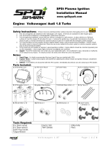
Sof tware and
Manuals
Ca bl e
s
Pow er Cor d
P
C
Foot Stand
Mo us e ( O pt ion)
Keyb oard
(Option)
P4 CPU c ooler (Option)
Ite ms included in the pa cka ge

G-MAX
TM
Flex ATX Series Us er’s M anual
P. E4
I . Cha ssi s
ŜDimension 410(D)mm x 89(W)mm x 305(H)mm
This chassis is made with m aterial complied wit h UL specificat ion and designed for
s pace saving and easy open wit h thum bscrew. There are one 5.25” and two 3. 5”
drive bays. This chassis complies with corresponding EMC and safet y regulations.
II. Motherboard
See Motherboard Manual for det ails.
III. Power Supply
The ATX swit ching power supply included with this product s upports soft off function.
Hence, the syst em can be shut down automatically. Default input voltage setting is
230V.
Note : Please check the voltage requirements in the count ry y ou reside before
turning on the PC.
IV. System Component Installation
■HDD As s em bly
1. Unscrew each side of the chassis and push the panel t ogether with t he uppercase
toward the front.
2. Take both the screws on the front end off and pull the HDD supporting frame out.
HDD fram e

G-MAX
TM
Flex ATX Series Us er’s M anual
P. E5
Install cooler on to
p
of CP U
Click cooler lock
on the pin at sides
of CPU socket.
Leve
r
3. CPU
In this section you will find the gis t of CPU installation.
3-1. Insert CPU into the CPU socket. Before inst allation, lift up the lever and align
the cut of the CPU with the marking on the socket.
3-2. Pull down t he lever to lock the CPU on the s ocket after inst allation.
3-3. Apply t hermal grease to the t op of the CPU. Thermal grease should cover the
entire s urface of t he integrat ed heat spreader. M ake sure that you should keep
the cooler tight against the CPU to obtain the best cooling perform ance.
3-4. Connec t fan power connector to CPU FAN on the motherboard.
A. Fo r I ntel
Pe ntium
Ƿ
and Intel
Ce l e r o n
processors
B. For I ntel
Pe n ti u m
4 processors
CPU Pin
A
pply thermal grease to the top
of the CPU properly.
Leve
r
CP U Pin
A
pply therm al grease to the top
of t he CPU properly.

G-MAX
TM
Flex ATX Series Us er’s M anual
P. E6
SDRAM
Set CPU clock frequency in BIOS Setup if needed, see Motherboard Manual for details.
4. Memory
Click cooler lock
on t he pin at sides
of CPU socket.
Install cooler on
top of CPU
Power Supply
Notches at sides
of m odule
Position not ches. Make sure that the notches should align the pin on memory
slot on the m ot herboard

G-MAX
TM
Flex ATX Series Us er’s M anual
P. E7
Locks: make sure they hook up t he notches at sides of module
5. Insert the HDD into the frame and position the sc rews accordingly.
In this section we will guide you to install memor
y
module. First, make sure th
e
position notches at the bott om of the module should align to t he pins on the modul
e
sockets on the m ot herboard, then push the module downward until the locks hoo
k
up not ches at s ides.
Position not ches. Make sure that the notches should align the pin on memory
slot on the m ot herboard
Notches at sides
of m odule
DDR

G-MAX
TM
Flex ATX Series Us er’s M anual
P. E8
Power connector
6. Connect the IDE cable included in t he accessory box to t he connector on the hard
disc. Make s ure that the RED wire on the ribbon should be connected t o PIN 1 of
hard drive.
7. Connec t power connector to the hard disc.
8. Put the assembled HDD fram e back to t he chass is and t ighten t he screws
accordingly.
Connect to HDD dis c
Tight en the screw.

G-MAX
TM
Flex ATX Series Us er’s M anual
P. E9
IDE-1
CAUTIO N!
Screwed carefully for t he flat cables.
9. Connect another end of the IDE c onnec tor to the IDE-1 bus on t he motherboard.
10. Put the assembled HDD frame back to the chassis and tight en the screws t o the
chassis.
11. Put the front panel bac k t o the chassis.
12. Confirming all the c onnec tions were done correct ly.
HDD frame

G-MAX
TM
Flex ATX Series Us er’s M anual
P. E1 0
V. Syste m Insta lla tion a nd Use r’s Gu ide
■Front Panel
*PCMCIA
Button
Floppy
*P CM CIA Por t
*1394 Hub
*SPDIF
CD-ROM Tray
CD-ROM Button
Power Button
P ower LE D
HDD LE D
Audio Out
MIC In
USB Hub 2.0/ 1.1
Drive Cabinet Door
Floppy

G-MAX
TM
Flex ATX Series Us er’s M anual
P. E11
ŜRear Panel
ŜNote
I. To avoid breaking dis c during high-speed operation, we recom mend you to
use high quality CD/ Recordable CD/ Re-writable CD.
II. Specification with “Ŏ” mark are subject to change without notice.
III. For latest drivers update, please visit our Web site listed below:
http:// www.gigabyt e.c om.tw/products/plat_index.htm → FA Series →
Not es
Ŝ
Important Safety Instructions
Cau ti on –To reduce the risk of fire, use only No.26 AWG or larger telephone line cord.
Caution –Always disc onnect all telephone lines from the wall outlet before servicing or
dis assem bly this equipm ent.
Cau ti on –Danger of explosion if battery is incorrectly replaced.
Replace only with the same or equivalent type recomm ended by the
manufac turer. Dispose used batt eries acc ording to the m anufacturer’s
instructions.
Power Inlet
Keyboard Port (PS/ 2)
COM Port
COM Port / VGA Port
US B Hub
A
udio Out
A
udio I
n
MIC In
Mouse Port(PS/2)
LPT Port
LAN Port
Volt age Switch
Game Port
* 1394 Hub

G-MAX
TM
Flex ATX Series Us er’s M anual
P. E1 2
▓User’s Guide for SPDIF (For those models with SPDIF only)
1. Insert the Driver CD t hat was included in access ory box int o your CD-ROM. Inst all
or upgrade t he audio driver.
2. If SPDIF can’t out put normally after audio driver is updated, pleas e operate st ep by
step as below.
(A)Click on Start Programs Accessories Entertainm ent
Volume Control

G-MAX
TM
Flex ATX Series Us er’s M anual
P. E1 3
(B)Volume Control Options Advanced Controls
Propert ies Playback SPDIF OK
Select
Select
Enable Select
A
dd

G-MAX
TM
Flex ATX Series Us er’s M anual
P. E1 4
(C)Select SPDIF Advanced Sam pling rate conversion for SPDIF output
Close Finish
3. Similar procedures will be applied to different Windows
®
operat ing systems t o
enable t he SPDIF function.
Enable

G-MAX
TM
Flex ATX Series Us er’s M anual
P. E1 5
For th ose mo dels wi t h SPDI F on ly
▓User’s Guide for Digit al CD audio
1. Insert the Driver CD that was included in accessory box into your CD-ROM. Install or
upgrade the audio driver.
2. If the digital CD audio can’t output normally after audio driver is updated, please
operate st ep by step as below.
(A) Click on Start Settings Cont rol Panel
(B) Selec t “System Propert ies”

G-MAX
TM
Flex ATX Series Us er’s M anual
P. E1 6
(C) Selec t Hardware Device Manager

G-MAX
TM
Flex ATX Series Us er’s M anual
P. E1 7
(D) Selec t DVD/CD-ROM drivers Properties
(E) Selec t ”Enable digital CD audio for this CD-ROM device” OK

G-MAX
TM
Flex ATX Series Us er’s M anual
P. E1 8
(F) Select “YES”
3. The “Enable digit al CD audio for this CD-ROM device” option in Windows
®
ME and
Windows
®
XP is default set to “Enable”.
4. Similar procedures will be applied to different Windows
®
operating systems t o enable
the digital CD audio function.
/