Page is loading ...

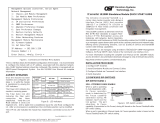
iConverter STM 1 Coax to Fiber Media Converter
Plug-In User Manual
Product Overview
The iConverter STM 1 coax to ber media converter converts
155.52 Mbps STM-1e coax to STM-1 ber.
The coax port provides two mini-BNC 75Ω coax connectors
that comply with the ITU-T G.703 and Telcordia GR-253
standards for CMI coded 155.52 Mbps electrical interfaces.
Installation Procedure
1) Congure DIP-switches
2) Install Module in Chassis and Connect Cables
2) Verify Operation
1) CONFIGURE DIP-SWITCHES
SW1 - LINK SEGMENT / LINK PROPAGATE “LS / LP”
This DIP-switch has no effect. The LS function
of this DIP-switch has been disabled to enhance
compatibility with third-party ber optic devices. The
STM-1 media converter operates in LP mode.
SW2 - REMOTE FAULT DETECT “Norm / RFD”
When the DIP-switch is in the “RFD” position, the
module is congured for Remote Fault Detection.
When the DIP-switch is in the “Norm” position (factory
setting), Remote Fault Detection is disabled and
operates in LP mode.
LINK MODES
Link Propagate (LP)
The LP mode transmits a link signal only when a link signal is detected. Utilizing this
conguration, a loss of a receive link signal will continue to propagate forward to the next
port in the network. Figure 2(a), on the following page, indicates a loss of link on the ber
port. This fault condition is ‘propagated’ forward causing the coax port to drop its link due to
the propagated fault. This setting allows the loss of a link to be detected by SNMP or other
managed network devices.
Remote Fault Detect (RFD)
The RFD mode transmits a link signal only when a link signal is detected. When a loss of
link is detected, this mode will perform both a loop back and propagate forward. Figure 2(b),
indicates a loss of Rx ber. The fault is looped back in the opposite direction causing the port
on the other media converter to lose its ber link. It also propagates the fault forward toward
the coax port causing the coax port to lose its link. Because the other unit is congured for
Link Propagate, the loss of ber link causes the coax port to drop its link due to the propagated
fault condition.
Form 040-8899S-002A 6/09
Page 1
Omnitron Systems Technology * 140 Technology Dr. #500 * Irvine, CA 92618
949.250.6510 tel * 949.250.6514 fax * www.omnitron-systems.com

Note: It is not permitted to set both media converters to any RFD mode. A lockup condition
will occur.
Figure 2: Link Modes
For detailed information on the operation of the different Link Modes, download the application
note “iConverter Link Modes” available on Omnitron’s web page:
http://www.omnitron-systems.com/downloads_iconverter.php
2) INSTALL MODULE IN CHASSIS AND CONNECT CABLES
a. Carefully slide the module into an open slot in the chassis. Align the module with the
installation guides and ensure that the module is rmly seated against the backplane.
Secure the module by fastening the front panel thumbscrew (push in and turn clockwise
to tighten) to the chassis front. Verify the “Pwr” LED is ON (indicating the chassis is
powered).
b. Insert the 155Mbps OC-3 SFP into Port 1 SFP receptacle on the STM 1 converter.
NOTE: The release latch of the ber transceiver must be in the closed position before
insertion.
c. The STM-1e interface on the converter utilizes mini BNC connectors. When connecting
to full size BNC connectors use the supplied adapter cables.
d. Connect an appropriate multimode or single-mode ber cable to the ber transceiver
port on the STM 1 converter. It is important to ensure that the transmit (Tx) is attached
to the receive side of the device at the other end and the receive (Rx) is attached to the
transmit side.
WARNING: Do not attempt to remove the STM-1e device from the SFP port on the module.
This will cause damage to the module and the STM-1e device.
Page 3
3) VERIFY OPERATION
Once the module has been installed and congured per steps 1 and 2, verify the module is
operational by viewing the LED indicators.
Legend Color OFF State ON State
Pwr Amber No power applied Unit is powered
P1 Lk Green Port is not linked Port is linked
P2 Lk Green Port is not linked Port is linked
Table 3: LED Indicators
Page 2
/