
User´s Guide
HXC cameras – Release 2 (Camera Link
®
)
Document Version: v2.0
Release: 04.07.2017
Document Number: 11080602

2
Table of Contents
1. General Information ................................................................................................. 4
2. General safety instructions ..................................................................................... 5
3. Intended Use ............................................................................................................. 5
4. General Description ................................................................................................. 5
5. Camera Models ......................................................................................................... 6
5.1 HXC – Cameras with C-Mount ................................................................................ 6
5.2 HXC-F – Cameras with F-Mount ............................................................................. 7
6. ProductSpecications ............................................................................................ 8
6.1 Identication of Firmware version ........................................................................... 8
6.2 Sensor Specications ............................................................................................. 8
6.2.1 Identication of Sensor Version ........................................................................ 8
6.2.2 Quantum Efciency for Baumer HXC Cameras ............................................... 8
6.2.3 Shutter .............................................................................................................. 8
6.2.4 Digitization Taps ............................................................................................... 9
6.3 Timings .................................................................................................................. 10
6.3.1 Free Running Mode ........................................................................................ 10
6.3.2 Trigger Mode ...................................................................................................11
6.4 Field of View Position ............................................................................................ 15
6.5 Process- and Data Interface ................................................................................. 16
6.5.1 Pin-Assignment Camera Link
®
Interface ........................................................ 16
6.5.2 Pin-Assignment Power Supply and Digital IOs .............................................. 17
6.5.3 LED Signaling ................................................................................................. 17
6.6 Environmental Requirements ................................................................................ 18
6.6.1 Temperature and Humidity Range .................................................................. 18
6.6.2 Heat Transmission .......................................................................................... 18
6.6.3 Mechanical Tests ............................................................................................ 19
7. Software .................................................................................................................. 20
7.1 Baumer GAPI ........................................................................................................ 20
8. Camera Functionalities .......................................................................................... 21
8.1 Image Acquisition .................................................................................................. 21
8.1.1 Image Format ................................................................................................. 21
8.1.2 Pixel Format ................................................................................................... 22
8.1.3 Exposure Time................................................................................................ 24
8.1.4 PRNU / DSNU Correction (FPN - Fixed Pattern Noise) ................................. 24
8.1.5 High Dynamic Range (HDR) .......................................................................... 25
8.1.6 Look-Up-Table ................................................................................................ 25
8.1.7 Gamma Correction ......................................................................................... 26
8.1.8 Region of Interest (ROI) and Multi-ROI .......................................................... 26
8.1.9 Binning / Subsampling .................................................................................... 28
8.1.10 Brightness Correction (Binning Correction) .................................................. 29
8.2 Color Adjustment – White Balance ....................................................................... 29
8.2.1 User-specic Color Adjustment ...................................................................... 29
8.2.2 One Push White Balance ............................................................................... 29

3
8.3 Analog Controls ..................................................................................................... 30
8.3.1 Offset / Black Level ......................................................................................... 30
8.3.2 Gain digital...................................................................................................... 30
8.4 Defect Pixel Correction ......................................................................................... 31
8.4.1 General information ........................................................................................ 31
8.4.2 Correction Algorithm ....................................................................................... 31
8.4.3 Defectpixellist ................................................................................................. 31
8.5 Sequencer ............................................................................................................. 32
8.5.1 General Information ........................................................................................ 32
8.5.2 Examples ........................................................................................................ 33
8.5.3 Capability Characteristics of Baumer-GAPI Sequencer Module .................... 33
8.5.4 Double Shutter ............................................................................................... 34
8.6 Process Interface .................................................................................................. 35
8.6.1 Digital IOs ....................................................................................................... 35
8.6.2 Trigger Input / Trigger Delay ........................................................................... 37
8.6.3 Trigger Source ................................................................................................ 38
8.6.4 Debouncer ...................................................................................................... 39
8.6.5 Flash Signal .................................................................................................... 39
8.6.6 Timer............................................................................................................... 40
8.7 User Sets .............................................................................................................. 41
8.8 Factory Settings .................................................................................................... 41
9. Camera Link
®
Interface ........................................................................................... 42
9.1 Channel Link and LVDS Technology ..................................................................... 42
9.2 Camera Signals .................................................................................................... 42
9.2.1 Serial Communication .................................................................................... 42
9.2.2 Camera Control .............................................................................................. 43
9.2.3 Video Data ...................................................................................................... 43
9.3 Camera Link
®
Taps ................................................................................................ 44
9.3.1 Tap Conguration ........................................................................................... 44
9.3.2 Tap Geometry ................................................................................................. 48
10. Lens install .............................................................................................................. 50
11. Cleaning .................................................................................................................. 51
12. Transport / Storage ................................................................................................ 51
13. Disposal .................................................................................................................. 52
14. Warranty Information ............................................................................................. 52
15. Conformity .............................................................................................................. 53
15.1 CE ....................................................................................................................... 53
15.2 FCC – Class B Device ........................................................................................ 53
15.3 Korean Conformity .............................................................................................. 53
16. Support .................................................................................................................... 55

4
1. General Information
Read these manual carefully and observe the notes and safety instruc-
tions!
Notice
This is the technical documentation for the Baumer HXC Series. The Baumer Camera
HXC 13 has it own technical documentation!
Thank you for purchase a camera of the Baumer family. This User´s Guide describes how
to connect, set up and use the camera.
Keep the User´s guide store in a safe place and transmit them to the eventually following
users. Please also note the provided technical data sheet.
Target group for this User´s Guide
This User's Guide is aimed at experienced business users, which want to integrate
camera(s) into a vision system.
Copyright
Any duplication or reprinting of this documentation, in whole or in part, and the reproduc-
tion of the illustrations even in modied form is permitted only with the written approval of
Baumer. This document is subject to change without notice.
Classicationofthesafetyinstructions
In the User´s Guide, the safety instructions are classied as follows:
Notice
Gives helpful notes on operation or other general recommendations.
Caution
Pictogram
Indicates a possibly dangerous situation. If the situation is not avoided, slight
or minor injury could result or the device may be damaged.

5
2. General safety instructions
Observe the the following safety instructions when using the camera to avoid any damage
or injuries.
Caution
A power supply with electrical isolation is required for proper operation of the
camera. Otherwise the device may be damaged.
Caution
Provide adequate dissipation of heat, to ensure that the temperature does
not exceed the spedied temperature (+65 °C /+149 °F).
The surface of the camera may be hot during operation and immediately
after use. Be careful when handling the camera and avoid contact over a
longer period.
Caution
When xing the Camera Link
®
cable with too much force the screws might
get damaged.
The maximum torque is 2.5 inch lbf [0.3 Nm].
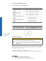
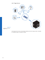
3. Intended Use
The camera is used to capture images that can be transferred over two Camera Link
®
interfaces to a PC.
Notice
Use the camera only for its intended purpose! For any use that is not described in the
technical documentation poses dangers and will void the warranty. The risk has to be
borne solely by the unit´s owner.
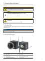
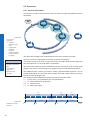
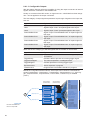
4. General Description
1
2
3
4
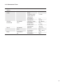
56
Nr. Description Nr. Description
1 (respective) lens mount 4 Digital-IO supply
2 Power supply 5
Camera Link
®
Base socket
3
Camera Link
®
Full socket
6 Signaling-LED

6
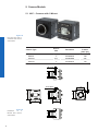
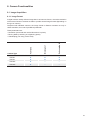
5. Camera Models
5.1 HXC – Cameras with C-Mount
Camera Type
Sensor
Size
Resolution
Full
Frames
[max. fps]
HXC20 2/3" 2048x1088 337
HXC40 1" 2048x2048 180
HXC20c 2/3" 2048x1088 337
HXC40c 1" 2048x2048 180
Dimensions
52
52
26
26
36
36
UNC 1/4-20
16 x M3 depth 6
26
36
36
36
4 x M3 depth 6
37,4
Figure1►
Front and rear view of
a Baumer HXC camera
with C-Mount
Figure2►
Dimensions of a
Baumer HXC camera
with C-Mount.

7
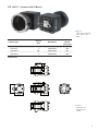
5.2 HXC-F – Cameras with F-Mount
Camera Type
Sensor
Size
Resolution
Full
Frames
[max. fps]
HXC20-F 2/3" 2048x1088 337
HXC40-F 1" 2048x2048 180
HXC20c-F 2/3" 2048x1088 337
HXC40c-F 1" 2048x2048 180
Dimensions
52
52
26
26
3636
UNC 1/4-20
16 x M3 depth 6
26
36
37
◄Figure3
Front view of a Baumer
HXC camera with F-
Mount
◄Figure4
Dimensions of a
Baumer HXC-F
camera.

8
6. ProductSpecications
6.1 IdenticationofFirmwareversion
• Label on Camera ("R2.0" is Firmware 2.0)
• BGAPI 1.x - CL Cong Tool: CameraInformation: Hardware Version (CID Firmware
1.0 starts with 02 / CID Firmware 2.0 starts with 03 (e.g. CID:030004 - Firmware 2.0)
• Read out register 0x00000088 (see HXC Register Description Release 2)
6.2 SensorSpecications
6.2.1 IdenticationofSensorVersion
• Read out register 0xF0004600 (see HXC Register Description Release 2)
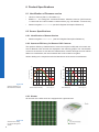
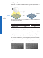
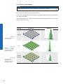
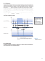
6.2.2 QuantumEfciencyforBaumerHXCCameras
The quantum efciency characteristics of monochrome (also in NIR) and color matrix sen-
sors for Baumer HXC cameras are displayed in the following graphs. The characteristic
curves for the sensors do not take the characteristics of lenses and light sources without
lters into consideration, but are measured with an AR coated cover glass.
Values relating to the respective technical data sheets of the sensors manufacturer.
350 450 550 650 750 850 950 1050
Wave Length [nm]
Quantum Efficiency [%]
HXC 20/40 (monochrome)
NIR
350 450 550 650 750 850 950 1050
Wave Length [nm]
Quantum Efficiency [%]
HXC 20/40 (color)
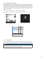
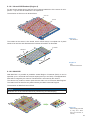
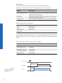
6.2.3 Shutter
All cameras of the HXC series are equipped with a global shutter.
Figure5►
Quantum efciency for
Baumer HXC cameras.
Figure6►
Structure of an imag-
ing sensor with global
shutter

9
Global shutter means that all pixels of the sensor are reset and afterwards exposed for a
specied interval (t
exposure
).
For each pixel an adjacent storage circuit exists. Once the exposure time elapsed, the
information of a pixel is transferred immediately to its circuit and read out from there.
Due to the fact that photosensitive area gets "lost" by the implementation of the circuit
area, the pixels are equipped with microlenses, which focus the light on the pixel.
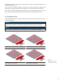
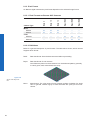
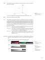
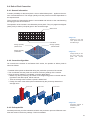
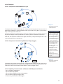
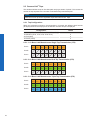
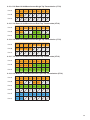
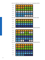
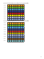
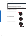
6.2.4 Digitization Taps
The Truesense sensors, employed in Baumer HXC cameras can be read out up to 16
channels in parallel.
Notice
More channels increase the speed (framerate), but the use of more channels produces
a higher heat generation. Use only the maximum required number of channels!
Notice
Due to sensor characteristics in 12 bit mode only 2 or 4 channels are available.
Readout with 16 Channels Readout with 8 Channels
Readout with 4 Channels Readout with 2 Channels
◄Figure7
Digitization Tap of the
Baumer HXC Cameras

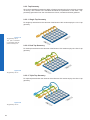
10
6.3 Timings
Notice
Overlapped mode can be switched off with setting the readout mode to sequential shut-
ter instead of overlapped shutter.
The image acquisition consists of two separate, successively processed components.
Exposing the pixels on the photosensitive surface of the sensor is only the rst part of the
image acquisition. After completion of the rst step, the pixels are read out.
The exposure time (t
exposure
) can be adjusted by the user, however, the time needed for the
readout (t
readout
) is given by the particular sensor, image format and conguration.
Baumer HXC cameras can be operated with two modes, the Free Running Mode and the
Trigger Mode.
The cameras can be operated non-overlapped
*)
or overlapped. Depending on the mode
used, and the combination of exposure and readout time:
Non-overlappedOperation OverlappedOperation
Here the time intervals are long enough
to process exposure and readout succes-
sively.
In this operation the exposure of a frame
(n+1) takes place during the readout of
frame (n).
Exposur
e
Readout
Exposur
e
Readout
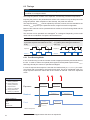
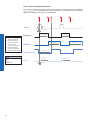
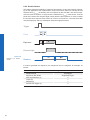
6.3.1 Free Running Mode
In the "Free Running" mode the camera records images permanently and sends them to
the PC. In order to achieve an optimal (with regard to the adjusted exposure time t
exposure
and image format) the camera is operated overlapped.
In case of exposure times equal to / less than the readout time (t
exposure
≤ t
readout
), the maxi-
mum frame rate is provided for the image format used. This is for overlapped mode. For
longer exposure times the frame rate of the camera is reduced. This is for sequential
mode.
Exposur
e
Readout
Flas
h
t
exposure(n)
t
flash(n)
t
flashdelay
t
flash(n+1)
t
readout(n+1)
t
readout(n)
t
exposure(n+1)
t
ash
= t
exposure
*) Non-overlapped means the same as sequential.
Image parameters:
Offset
Gain
Mode
Partial Scan
Timings:
A - exposure time
frame (n) effective
B - image parameters
frame (n) effective
C - exposure time
frame (n+1) effective
D - image parameters
frame (n+1) effective

11
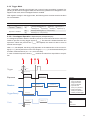
6.3.2 Trigger Mode
After a specied external event (trigger) has occurred, image acquisition is started. De-
pending on the interval of triggers used, the camera may operate non-overlapped or over-
lapped in this mode, when overlapped mode is enabled.
With regard to timings in the trigger mode, the following basic formulas need to be taken
into consideration:
Case Formula
t
exposure
< t
readout
(1) t
earliestpossibletrigger(n+1)
= t
readout(n)
- t
exposure(n+1)
(2) t
notready(n+1)
= t
exposure(n)
+ t
readout(n)
- t
exposure(n+1)
t
exposure
> t
readout
(3) t
earliestpossibletrigger(n+1)
= t
exposure(n)
(4) t
notready(n+1)
= t
exposure(n)
6.3.2.1 OverlappedOperation:t
exposure(n+2)
= t
exposure(n+1)
In overlapped operation attention should be paid to the time interval where the camera is
unable to process occuring trigger signals (t
notready
). This interval is situated between two
exposures. When this process time t
notready
has elapsed, the camera is able to react to
external events again.
After t
notready
has elapsed, the timing of (E) depends on the readout time of the current im-
age (t
readout(n)
) and exposure time of the next image (t
exposure(n+1)
). It can be determined by the
formulas mentioned above (no. 1 or 3, as is the case).
In case of identical exposure times, t
notready
remains the same from acquisition to acquisi-
tion.
Exposur
e
Readout
t
exposure(n)
t
readout(n+1)
t
readout(n)
t
exposure(n+1)
t
triggerdelay
t
min
Tr
igger
Flas
h
t
flash(n)
t
flashdelay
t
flash(n+1)
Tr
iggerReady
t
notready
Image parameters:
Offset
Gain
Mode
Partial Scan
Timings:
A - exposure time
frame (n) effective
B - image parameters
frame (n) effective
C - exposure time
frame (n+1) effective
D - image parameters
frame (n+1) effective
E - earliest possible trigger

12
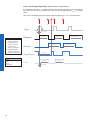
6.3.2.2 OverlappedOperation:t
exposure(n+2)
> t
exposure(n+1)
If the exposure time (t
exposure
) is increased from the current acquisition to the next acquisi-
tion, the time the camera is unable to process occuring trigger signals (t
notready
) is scaled
down.
This can be simulated with the formulas mentioned above (no. 2 or 4, as is the case).
Exposure
Readout
t
exposure(n)
t
readout(n+1)
t
readout(n)
t
exposure(n+1)
t
exposure(n+2)
t
triggerdelay
t
min
Trigger
Flas
h
t
flash(n)
t
flashdelay
t
flash(n+1)
TriggerReady
t
notready
Image parameters:
Offset
Gain
Mode
Partial Scan
Timings:
A - exposure time
frame (n) effective
B - image parameters
frame (n) effective
C - exposure time
frame (n+1) effective
D - image parameters
frame (n+1) effective
E - earliest possible trigger

13
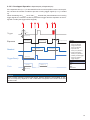
6.3.2.3 OverlappedOperation:t
exposure(n+2)
< t
exposure(n+1)
If the exposure time (t
exposure
) is decreased from the current acquisition to the next acquisi-
tion, the time the camera is unable to process occuring trigger signals (t
notready
) is scaled
up.
When decreasing the t
exposure
such, that t
notready
exceeds the pause between two incoming
trigger signals, the camera is unable to process this trigger and the acquisition of the im-
age will not start (the trigger will be skipped).
Exposur
e
Readout
t
exposure(n)
t
readout(n+1)
t
readout(n)
t
exposure(n+1)
t
exposure(n+2)
t
triggerdelay
t
min
Tr
igger
Flas
h
t
flash(n)
t
flashdelay
t
flash(n+1)
Tr
iggerReady
t
notready
Notice
From a certain frequency of the trigger signal, skipping triggers is unavoidable. In gen-
eral, this frequency depends on the combination of exposure and readout times and
shutter mode.
Image parameters:
Offset
Gain
Mode
Partial Scan
Timings:
A - exposure time
frame (n) effective
B - image parameters
frame (n) effective
C - exposure time
frame (n+1) effective
D - image parameters
frame (n+1) effective
E - earliest possible trigger
F - frame not started /
trigger skipped

14
6.3.2.4 Non-overlappedOperation
If the period between two trigger pulses is long enough, so that the image acquisitions
(t
exposure
+ t
readout
) run successively, the camera operates non-overlapped. In the following
gure is the shutter mode set to non-overlapped.
Exposure
Readout
t
exposure(n)
t
readout(n+1)
t
readout(n)
t
exposure(n+1)
t
triggerdelay
t
min
Trigger
Flas
h
t
flash(n)
t
flashdelay
t
flash(n+1)
TriggerReady
t
notready
Image parameters:
Offset
Gain
Mode
Partial Scan
Timings:
A - exposure time
frame (n) effective
B - image parameters
frame (n) effective
C - exposure time
frame (n+1) effective
D - image parameters
frame (n+1) effective
E - earliest possible trigger

15
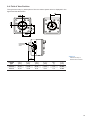
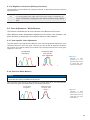
6.4 FieldofViewPosition
The typical accuracy by assumption of the root mean square value is displayed in the
gures and the table below:
±Z
Photosensitive
surface of the
sensor
±Y
±X
±ß
M
M
R
R
±X
±Y
Camera
Type
± x
M,typ
[mm]
± y
M,typ
[mm]
± x
R,typ
[mm]
± y
R,typ
[mm]
± β
typ
[°]
± z
typ
[mm]
HXC20 0,18 0,18 0,14 0,14 1,2 0,025
HXC40 0,18 0,18 0,14 0,14 1,2 0,025
◄Figure8
Sensor accuracy of
Baumer HXC cameras.

16
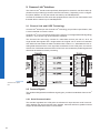
6.5 Process- and Data Interface
6.5.1 Pin-Assignment Camera Link
®
Interface
Notice
Baumer
Type: HXCXXx (xxxxxxx)
S/N: 000XXXXX
R1.0
CL FULL
CL BASE
C
L BA
S
E
C
L F
U
L
L
The camera has two Camera Link sockets. To differentiate between Cam-
era Link Base and CamerLink Full socket, please look at the label.
You can not use the CL Full socket alone!
Caution
When xing the Camera Link
®
cable with too much force the screws might
get damaged.
The maximum torque is 2.5 inch lbf [0.3 Nm].
Date / Camera Link
®
Full
1 GND 10 Z2- 19 Y3+
2 Y0- 11 ZCLK- 20 100 Ω Term.
3 Y1- 12 Z3- 21 Z0+
4 Y2- 13 GND 22 Z1+
5 YCLK- 14 GND 23 Z2+
6 Y3- 15 Y0+ 24 ZCLK+
7 100 Ω Term. 16 Y1+ 25 Z3+
8 Z0- 17 Y2+ 26 GND
9 Z1- 18 YCLK+
Data / Control / Camera Link
®
Base
1 GND 10 CC2+ 19 X3+
2 X0- 11 CC3- 20 SERTC-
3 X1- 12 CC4+ 21 SERTFG+
4 X2- 13 GND 22 CC1+
5 XCLK- 14 GND 23 CC2-
6 X3- 15 X0+ 24 CC3+
7 SERTC+ 16 X1+ 25 CC4-
8 SERTFG- 17 X2+ 26 GND
9 CC1- 18 XCLK+

17
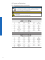
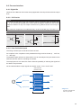
6.5.2 Pin-AssignmentPowerSupplyandDigitalIOs
Caution
A power supply with electrical isolation is required for proper operation of the
camera. Otherwise the device may be damaged.
M8 / 3 pins M8 / 8 pins
1
4
3
8
5
73
1
4
2
6
8
5
73
1
4
2
6
7
1 (brown) Power V
CC
1 (white) Line 9
3 (blue) GND 2 (brown) Line 1
4 (black) not used 3 (green) Line 0
4 (yellow) GND
5 (grey) U
ext
6 (pink) Line 7
7 (blue) Line 8
8 (red) Line 2
Power Supply
Power VCC 9,6 VDC ... 30 VDC
I
Mono8, Camera Link base, dual tap, 40 MHz; 190 mA .. 550
mA
Mono8, Camera Link full, 10 tap, 48 MHz; 200 mA .. 620 mA
Power consumption approx. 5.5 Watt (with camera factory settings)
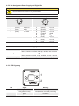
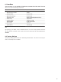
6.5.3 LED Signaling
2
1
LED Signal Meaning
1
green Transmitting
red (yellow in both) Conguration command processing
2
green Power on
yellow Readout active

18
6.6 EnvironmentalRequirements
6.6.1 Temperature and Humidity Range
*)
Temperature
Storage temperature
HXC20 -10 °C ... +70 °C ( +14 °F ... +158 °F)
HXC40 -10 °C ... +70 °C ( +14 °F ... +158 °F)
Operating temperature*
HXC20 +5 °C ... +60 °C (+41 °F ... +140 °F)
HXC40 +5 °C ... +60 °C (+41 °F ... +140 °F)
Housing operating temperature
**)***)
HXC20 max. +65 °C (+149 °F)
HXC40 max. +65 °C (+149 °F)
Internal operating temperature
HXC20 max. +60 °C (+140 °F)
HXC40 max. +60 °C (+140 °F)
Humidity
Storage and Operating Humidity 10% ... 90%
Non-condensing
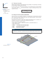
6.6.2 Heat Transmission
Caution
Provide adequate dissipation of heat, to ensure that the temperature does
not exceed the spedied temperature (+65°C /+149°F).
The surface of the camera may be hot during operation and immediately
after use. Be careful when handling the camera and avoid contact over a
longer period.
It is very important to provide adequate dissipation of heat, to ensure that the housing
temperature does not reach or exceed +65°C (+149°F). As there are numerous possibili-
ties for installation, Baumer do not speciy a specic method for proper heat dissipation,
but suggest the following principles:
▪ operate the cameras only in mounted condition
▪ mounting in combination with forced convection may provide proper heat dissipation
*) Please refer to the respective data sheet.
**) Measured at temperature measurement point (T).
***) Housing temperature is limited by sensor specications.
Figure9►
Temperature measure-
ment points of Baumer
HXC cameras.

19
6.6.3 Mechanical Tests
Environmental
Testing
Standard Parameter
Vibration, sinu-
sodial
IEC 60068-2-6 Search for Reso-
nance
10-2000 Hz
Amplitude under-
neath crossover
frequencies
1.5 mm
Acceleration 1 g
Test duration 15 min
Vibration,
broad band
IEC 60068-
2-64
Frequency range 20-1000 Hz
Acceleration 10 g
Displacement 5.7 mm
Test duration 300 min
Shock IEC 60068-
2-27
Puls time 11 ms / 6
ms
Acceleration 50 g / 100 g
Bump IEC60068-2-
29
Pulse Time 2 ms
Acceleration 80 g

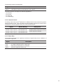
20
7. Software
7.1 BaumerGAPI
Baumer GAPI stands for Baumer “Generic Application Programming Interface”. With this
API Baumer provides an interface for optimal integration and control of Baumer cameras.
This software interface allows changing to other camera models.
It provides interfaces to several programming languages, such as C, C++ and the .NET™
Framework on Windows
®
, as well as Mono on Linux
®
operating systems, which offers the
use of other languages, such as e.g. C# or VB.NET.
The HXC camera features are in general supported by Baumer GAPI v 1.7.2. However,
to use the new release 2 features (e.g. HDR and Multi-ROI) Baumer GAPI v 2.1 is re-
quired.
Notice
There is currently no Baumer GAPI version for Linux available with support for
Camera Link
®
.
Notice
Please note the extra instructions to the software Baumer GAPI. Specically for
Camera Link
®
Cameras, the "User´s Guide CLCong Tool".
Page is loading ...
Page is loading ...
Page is loading ...
Page is loading ...
Page is loading ...
Page is loading ...
Page is loading ...
Page is loading ...
Page is loading ...
Page is loading ...
Page is loading ...
Page is loading ...
Page is loading ...
Page is loading ...
Page is loading ...
Page is loading ...
Page is loading ...
Page is loading ...
Page is loading ...
Page is loading ...
Page is loading ...
Page is loading ...
Page is loading ...
Page is loading ...
Page is loading ...
Page is loading ...
Page is loading ...
Page is loading ...
Page is loading ...
Page is loading ...
Page is loading ...
Page is loading ...
Page is loading ...
Page is loading ...
Page is loading ...
Page is loading ...
-
 1
1
-
 2
2
-
 3
3
-
 4
4
-
 5
5
-
 6
6
-
 7
7
-
 8
8
-
 9
9
-
 10
10
-
 11
11
-
 12
12
-
 13
13
-
 14
14
-
 15
15
-
 16
16
-
 17
17
-
 18
18
-
 19
19
-
 20
20
-
 21
21
-
 22
22
-
 23
23
-
 24
24
-
 25
25
-
 26
26
-
 27
27
-
 28
28
-
 29
29
-
 30
30
-
 31
31
-
 32
32
-
 33
33
-
 34
34
-
 35
35
-
 36
36
-
 37
37
-
 38
38
-
 39
39
-
 40
40
-
 41
41
-
 42
42
-
 43
43
-
 44
44
-
 45
45
-
 46
46
-
 47
47
-
 48
48
-
 49
49
-
 50
50
-
 51
51
-
 52
52
-
 53
53
-
 54
54
-
 55
55
-
 56
56


Baumer HXC20NIR Operating instructions
- Category
- Security cameras
- Type
- Operating instructions
Ask a question and I''ll find the answer in the document
Finding information in a document is now easier with AI
Related papers
-
Baumer TXG20c Operating instructions
-
Baumer HXG40c User guide
-
Baumer VLG-22C.I User guide
-
-
Baumer VEXG-52M.R User guide
-
Baumer MXGC20c User guide
-
Baumer VLG-20M User guide
-
Baumer HXC40c Quick start guide
-
Baumer VCXU-31C Operating instructions
-
Other documents
-
 FastVision FastCamera13 User manual
-
Basler racer Camera Link Owner's manual
-
Haier Refrigerator HXC-576 User manual
-
-
JAI SW-2000M-CL-65 User manual
-
-
-
Sony IMX327LQR User manual
-
-
 Chroma C4-DSP User manual

