
ii
Table of Contents
Introduction....................................................................................................................................................................1
Features.......................................................................................................................................................................1
Types of User Input Devices Supported:.....................................................................................................................1
Operating Systems Supported ....................................................................................................................................1
Limitations....................................................................................................................................................................2
Materials.........................................................................................................................................................................3
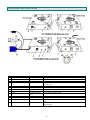
Features and Functions................................................................................................................................................4
Preparation for Installation...........................................................................................................................................5
Installation......................................................................................................................................................................6
The Local Unit..............................................................................................................................................................6
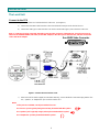
Connect to the CPU..................................................................................................................................................6
Connect the Local Devices.......................................................................................................................................7
Connect the CAT5 Cable..........................................................................................................................................8
The Remote Unit..........................................................................................................................................................9
Connect the Remote Devices...................................................................................................................................9
Connect the CAT5 cable.........................................................................................................................................10
Command Mode ..........................................................................................................................................................11
MAC Mode.................................................................................................................................................................12
DDC Support................................................................................................................................................................13
Common Applications................................................................................................................................................14
Technical Specifications ............................................................................................................................................15
Interconnection Cable Wiring Method ......................................................................................................................16
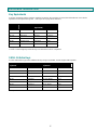
Keyboard Translation .................................................................................................................................................17
Key Equivalents.........................................................................................................................................................17
SUN’s 16 Extra Keys.................................................................................................................................................17
Troubleshooting..........................................................................................................................................................19
Index.............................................................................................................................................................................20
Warranty Information..................................................................................................................................................20
Table of Figures
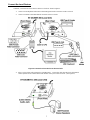
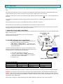
Figure 1- Connect the Local Unit to a CPU........................................................................................................................................6
Figure 2- Connect local user devices to the Local Unit......................................................................................................................7
Figure 3- Connect stereo speakers to XTENDEX Local Unit with audio support...............................................................................7
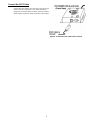
Figure 4- Connect the CAT5 cable to the Local Unit..........................................................................................................................8
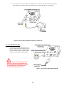
Figure 5- Connect the Monitor and Devices to the Remote Unit........................................................................................................9
Figure 6- Connect remote self-powered speakers to Remote Unit ..................................................................................................10
Figure 7- Connect CAT5 cable to the Remote Unit..........................................................................................................................10
Figure 15- MAC LED........................................................................................................................................................................12
Figure 16- DDC Update Button........................................................................................................................................................13
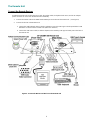
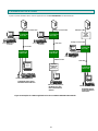
Figure 17- Examples of common applications for the ST-C5USBV-300 USB KVM Extender..........................................................14
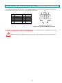
Figure 18- Pin positions in female RJ45 connector..........................................................................................................................16
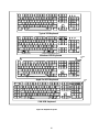
Figure 19- Keyboard Layouts...........................................................................................................................................................18


 1
1
 2
2
 3
3
 4
4
 5
5
 6
6
 7
7
 8
8
 9
9
 10
10
 11
11
 12
12
 13
13
 14
14
 15
15
 16
16
 17
17
 18
18
 19
19
 20
20
 21
21
 22
22
 23
23


NTI XTENDEX Series Operating instructions
 NTI ST-2C5VA-L-600 Operating instructions
NTI ST-C6HD-HDBT User manual
 NTI USB-SUN-R User manual
NTI ST-FOUSBVARS-LC User manual
 NTI XTENDEX VOPEX-C5SV-x User manual
 NTI ST-C6USB4K18GB-230T User manual
NTI ST-IPHD-LC-V4 User manual
NTI ENVIROMUX Series Installation guide


 Cables Direct VGA-VART300QD Datasheet
Sandberg 506-60 Datasheet
 T'nB CAJJ02 Datasheet
 T'nB CAJJ Datasheet
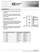 Commercial Electric 216 8C Operating instructions
 UNIMAX Houseware KVM Switch User manual
AVLink VGA-EDXW PRO Owner's manual
Network Technologies DVI-4 User manual


