1
2
4
42 U
13
Installation
Boîtiers pour bâti
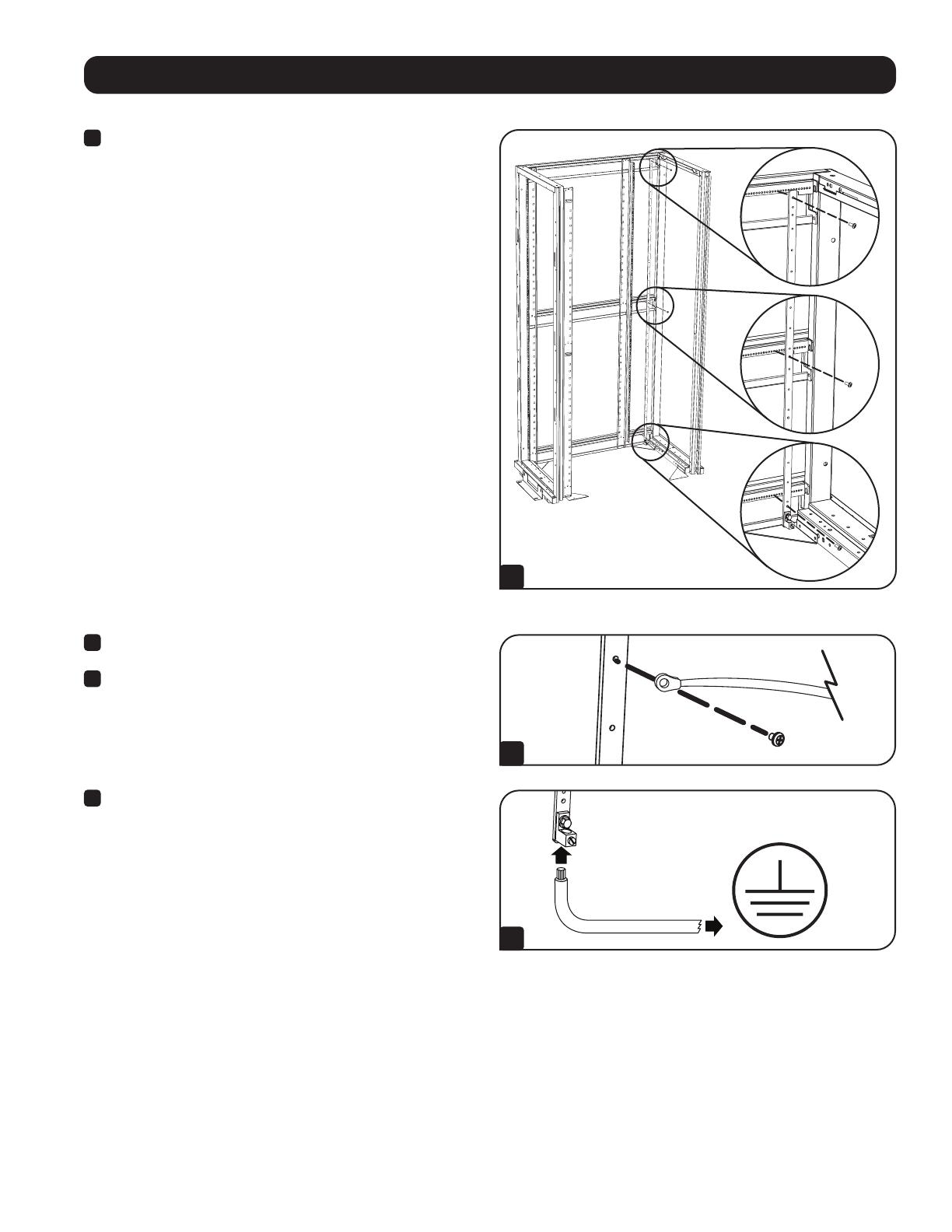
1
Pour un boîtier 42U, comme le SR42UB de Tripp Lite, fixer le
SRGROUND aux 3 montants horizontaux indexés au-dessus, au
milieu et dans le bas du boîtier. Les vis autotaraudeuses M4
incluses passeront dans les trois trous de passage (non filetés) sur
la barre, puis dans les montants du boîtier pour bâti.
Pour un boîtier 48U, comme le SR48UB de Tripp Lite, fixer le
SRGROUND aux montants du dessus et du milieu uniquement, car
la barre ne se rendra pas jusqu'en bas au niveau du montant du
bas.
Pour un boîtier 25U, comme le SR25UB de Tripp Lite, fixer
le SRGROUND25 aux 3 montants horizontaux indexés sur le
dessus et dans le bas du boîtier en utilisant le trou du haut et le
second trou à partir du bas. Les vis autotaraudeuses M4 incluses
passeront dans les deux trous de passage (non filetés) sur la
barre, puis dans les montants du boîtier pour bâti.
Pour un boîtier 24U, comme le SR24UB de Tripp Lite, fixer
le SRGROUND25 aux écrous à cage sur les rails horizontaux
supérieur et inférieur du boîtier en utilisant les trous supérieur et
inférieur
du SRGROUND25.
Remarque : Les instructions ci-dessus sont spécifiques au montage dans les
boîtiers SmartRack™ SR42UB, SR48UB, SR24UB ou SR25UB de Tripp Lite.
Le montage dans un boîtier d'une autre marque est possible, mais variera en
fonction de l'application. Plusieurs trous sont fournis le long de la barre de mise
à la terre pour permettre une installation fonctionnelle dans une configuration
en bâti peu importe la marque.
Remarque : Le placement peut varier et dépend de la configuration en bâti
particulière. Il est recommandé de mesurer la distance entre la barre et
l'équipement pour tenir compte de la longueur des rubans de mise à la terre.
Après avoir déterminé la longueur nécessaire, fixer la barre dans les trous
appropriés sur les montants horizontaux.
2
Fixer une extrémité du ruban de mise à la terre à la barre en
utilisant les vis M4 et les rondelles incluses.
3
Fixer l'autre extrémité du ruban de mise à la terre à la mise à la
terre sur l'équipement prévu.
4
Finalement, fixer la mise à la terre du système de l'installation à
la patte de mise à la terre dans le bas de la barre. La patte peut
accueillir des fils 2/0-14AWG.
MISE À LA TERRE DE
L'INSTALLATION


