Page is loading ...

VENT-FREE GAS WALL
HEATER
OWNER’S OPERATION AND
INSTALLATION MANUAL
INFRARED MODELS
MNSD2TPA, MNSD3TPA,
MNSD5TPA
MNSD3TPA-BB MNSD5TPA-BB
WARNING: If the information in this manual is not
followed exactly, a re or explosion may result causing
property damage, personal injury or loss of life.
— Do not store or use gasoline or other ammable va-
pors and liquids in the vicinity of this or any other
appliance.
— WHAT TO DO IF YOU SMELL GAS
• Do not try to light any appliance.
• Do not touch any electrical switch; do not use any
phone in your building.
•
Immediately call your gas supplier from a neighbor’s
phone. Follow the gas supplier’s instructions.
• If you cannot reach your gas supplier, call the re
department.
—
Installation and service must be performed by a quali-
ed installer, service agency or the gas supplier.
WARNING: This appliance is equipped for Natural and
Propane gas. Field conversion is not permitted other than
between natural or propane gases.
Questions, problems, missing parts? Before returning to your retailer, call
our customer service department at 1-866-573-0674, 7:30 am - 4:15 pm CST,
Monday through Friday or email customerser[email protected]
PFS
®
US

www.usaprocom.com
200218-01C2
INSTALLER: Leave this manual with the appliance.
CONSUMER: Retain this manual for future reference.
This is an unvented gas-red heater. It uses air (oxygen)
from the room in which it is installed. Provisions for ad-
equate combustion and ventilation air must be provided.
Refer to Air For Combustion and Ventilation section on
page 8 of this manual.
WARNING: Improper installation, adjustment, al-
teration, service or maintenance can cause injury or
property damage. Refer to this manual for correct in-
stallation and operational procedures. For assistance
or additional information consult a qualied installer,
service agency or the gas supplier.
This appliance may be installed in an aftermarket,* per-
manently located, manufactured (mobile) home, where
not prohibited by local codes.
This appliance is only for use with propane or natural
gas. Field conversion by any other means including the
use of a kit is not permitted.
* Aftermarket: Completion of sale, not for purpose of resale, from the manufacturer.
SAVE THIS BOOK
TABLE OF CONTENTS
Safety ........................................................ 3
Specications ............................................ 5
Qualied Installing Agency ........................ 6
Product Features ....................................... 6
Local Codes............................................... 6
Product Identication ................................. 7
Unpacking.................................................. 7
Water Vapor: A By-Product Of
Unvented Room Heaters ...................... 7
Air For Combustion and Ventilation ........... 8
Installation ............................................... 10
Operation ................................................. 19
Electrical Connection ............................... 21
Electrical Wiring ....................................... 21
Inspecting Heater .................................... 22
Care And Maintenance ............................ 23
Troubleshooting ....................................... 24
Replacement Parts .................................. 28
Accessories ............................................. 28
Service Hints ........................................... 29
Technical Service..................................... 29
Parts ........................................................ 30
Warranty .................................................. 36
PROCOM HEATING, INC. PATENT INFORMATION
This product may be covered by one or more of the following United States patents:
8,915,239 8,851,065 8,764,436 8,757,202 8,757,139 8,752,541 8,568,136
8,545,216 8,517,718 8,516,878 8,506,290 8,465,277 8,317,511 8,297,968
8,281,781 8,241,034 8,235,708 8,152,515 8,011,920 7,967,006 7,967,007
7,654,820 7,730,765 7,677,236 7,607,426 7,434,447

www.usaprocom.com
3200218-01C
SAFETY
IMPORTANT: Read this owner’s
manual carefully and completely
before trying to assemble, op-
erate, or service this heater.
Improper use of this heater can
cause serious injury or death
from burns, fire, explosion,
electrical shock and carbon
monoxide poisoning.
Only a qualied installer, service
agent, or local gas supplier may
install and service this product.
WARNING: Keep the appli-
ance area clear and free from
combustible materials, gasoline,
and other ammable vapors and
liquids.
WARNING: This appliance
can be used with propane or
natural gas. It is shipped from
the factory adjusted for use with
propane.
This appliance is only for use
with the type of gas indicated on
the rating plate. This appliance
is not convertible for use with
other gases.
DANGER: Carbon monoxide
poisoning may lead to death!
CARBON MONOXIDE POISONING: Early
signs of carbon monoxide poisoning resemble
the u, with headaches, dizziness or nausea.
If you have these signs, the heater may not be
working properly. Get fresh air at once! Have
heater serviced. Some people are more af-
fected by carbon monoxide than others. These
include pregnant women, people with heart or
lung disease or anemia, those under the inu-
ence of alcohol and those at high altitudes.
NATURAL AND PROPANE/LP GAS: Natural
and Propane/LP gas are odorless. An odor-
making agent is added to the gas. The odor
helps you detect a gas leak. However, the
odor added to the gas can fade. Gas may be
present even though no odor exists.
WARNING: Any change to
this heater or its controls can
be dangerous.
WARNING: Do not use any
accessories not approved for
use with this heater.
WARNING: Carefully super-
vise young children when they
are in the room with the heater.
WARNING: Make sure grill
guard is in place before running
heater.
WARNING: Due to high tem-
peratures, the appliance should
be located out of trafc and away
from furniture and draperies.
WARNING: Heater becomes
very hot when running. Keep
children and adults away from
hot surfaces to avoid burns or
clothing ignition. Heater will re-
main hot for a time after shutoff.
Allow surfaces to cool before
touching.
WARNING: Do not place
clothing or other flammable
material on or near the appli-
ance. Never place any objects
in the heater.

www.usaprocom.com
200218-01C4
1. Do not place Propane/LP supply tank(s)
inside any structure. Propane/LP supply
tank(s) must be placed outdoors.
2. Heaters with a maximum input over
6,000 Btu/Hr shall not be installed in a
bathroom. Heaters with a maximum input
over 10,000 Btu/Hr shall not be installed
in a bedroom.
3. This heater needs fresh air ventilation to
run properly. This heater has an Oxygen
Depletion Sensing (ODS) safety shutoff
system. The ODS shuts down the heater
if not enough fresh air is available. See
Air for Combustion and Ventilation, pages
8 and 9. If heater keeps shutting off, see
Troubleshooting, page 24.
4. Keep all air openings in front and bottom
of heater clear and free of debris. This will
ensure enough air for proper combustion.
5. If heater shuts off, do not relight until you
have provided fresh, outside air. If heater
keeps shutting off, have it serviced.
6. Do not run heater:
• Where ammable liquids or vapors are
used or stored.
• Under dusty conditions.
SAFETY
7. Before using furniture polish, wax, carpet
cleaner, or similar products, turn heater off.
If heated, the vapors from these products
may create a white powder residue within
burner box or on adjacent walls or furniture.
8. Always run heater with control knob at
PILOT/IGN, LOW (1) or HIGH (5) locked
positions. Never set control knob between
locked positions. Poor combustion and
higher levels of carbon monoxide may
result.
9. Do not use heater if any part has been
under water. Immediately call a qualied
service technician to inspect the room
heater and to replace any part of the
control system and any gas control which
has been under water.
10. Turn off and unplug heater and let cool
before servicing. Only a qualied service
person should service and repair heater.
11. Operating heater above elevations of
4,500 feet could cause pilot outage.
12. To prevent performance problems, do
not use propane/LP fuel tank of less than
100 lbs. capacity.

www.usaprocom.com
5200218-01C
MODEL MNSD2TPA MNSD3TPA MNSD5TPA
Ignition Electric Piezo Electric Piezo Electric Piezo
Gas Type Natural Gas Natural Gas Natural Gas
BTU (available) 10,000 20,000 30,000
Pressure Regulator Setting 6" W.C. 6" W.C. 6" W.C.
Inlet Gas Pressure*
(inches of water)
Maximum 9" Maximum 9" Maximum 9"
Minimum 7" Minimum 7" Minimum 7"
Gas Type Propane Gas Propane Gas Propane Gas
BTU (available) 10,000 18,000 26,000
Pressure Regulator Setting 10" W.C. 10" W.C. 10" W.C.
Inlet Gas Pressure*
(inches of water)
Maximum 14" Maximum 14" Maximum 14"
Minimum 11" Minimum 11" Minimum 11"
Heater Dimensions (HxWxD)
19
1
/
8
" × 14
1
/
8
" ×
7
1
/
8
"
23
1
/
2
" × 19
1
/
4
" × 8
3
/
4
"
23
1
/
2
" x 26
5
/
8
" x 8
3
/
4
"
Carton Dimensions (HxWxD)
22 ×16
3
/
4
" × 8
7
/
8
" 25
3
/
4
" × 21
3
/
4
" × 10" 25
3
/
4
" x 28
1
/
2
" x 10"
Heater Weight 15.1 lbs 21.6 lbs 28.1 lbs
Shipping Weight 18.1 lbs 25.6 lbs 33.1 lbs
MODEL MNSD3TPA-BB MNSD5TPA-BB
Ignition Electric Piezo Electric Piezo
Gas Type Natural Gas Natural Gas
BTU (available) 20,000 30,000
Pressure Regulator Setting 6" W.C. 6" W.C.
Inlet Gas Pressure*
(inches of water)
Maximum 9" Maximum 9"
Minimum 7" Minimum 7"
Gas Type Propane Gas Propane Gas
BTU (available) 18,000 26,000
Pressure Regulator Setting 10" W.C. 10" W.C.
Inlet Gas Pressure*
(inches of water)
Maximum 14" Maximum 14"
Minimum 11" Minimum 11"
Heater Dimensions (HxWxD)
23
1
/
2
" × 19
1
/
4
" × 8
3
/
4
" 23
1
/
2
" x 26
5
/
8
" x 8
3
/
4
"
Carton Dimensions (HxWxD)
25
3
/
4
" × 21
3
/
4
" × 10" 25
3
/
4
" x 28
1
/
2
" x 10"
Heater Weight 24.5 lbs 31 lbs
Shipping Weight 28.5 lbs 36 lbs
SPECIFICATIONS
Note: Dimensions listed are outer most points on the heater (includes control knobs and grill).
* For purposes of input adjustment.
Electrical Requirement for Blower Kit (if equipped)
Voltage • 120 VAC, 60 Hz

www.usaprocom.com
200218-01C6
LOCAL CODES
Install and use heater with care. Follow all
local codes. In the absence of local codes,
use the latest edition of The National Fuel
Gas Code, ANSI Z223.1/NFPA 54*.
*Available from:
American National Standards Institute, Inc.
25 West 43rd Street
New York, NY 10036
National Fire Protection Association, Inc.
1 Batterymarch Park
Quincy, MA 02269-9101
State of Massachusetts: The installation
must be made by a licensed plumber or
gas tter in the Commonwealth of Mas-
sachusetts.
Sellers of unvented propane or natural
gas-red supplemental room heaters shall
provide to each purchaser a copy of 527
CMR 30 upon sale of the unit.
In the State of Massachusetts the gas
cock must be a T-handle type. The State
of Massachusetts requires that a exible
appliance connector cannot exceed three
feet in length.
QUALIFIED INSTALLING AGENCY
Only a qualied agency should install and
replace gas piping, gas utilization equipment
or accessories, and repair and equipment ser-
vicing. The term “qualied agency” means any
individual, rm, corporation, or company that
either in person or through a representative
is engaged in and is responsible for:
a) Installing, testing, or replacing gas piping
or
b) Connecting, installing, testing, repairing,
or servicing equipment; that is experienced
in such work; that is familiar with all precau-
tions required; and that has complied with
all the requirement of the authority having
jurisdiction.
PRODUCT FEATURES
SAFETY PILOT
This heater has a pilot with an Oxygen Deple-
tion Sensing (ODS) safety shutoff system. The
ODS/pilot shuts off the heater if there is not
enough fresh air.
2 GAS OPTIONS AVAILABLE
Your heater is equipped to operate on either
Propane/LP or Natural gas. The heater is
shipped from the factory ready for connect-
ing to Propane/LP. The heater can easily be
changed to Natural gas by having your quali-
ed installer follow the instructions on page
14 and the markings on the heater.
PIEZO IGNITION SYSTEM
This heater is equipped with a piezo ignitor.
this system requires no matches, batteries, or
other sources to light heater.
THERMOSTATIC CONTROL
(Thermostat Models Only)
These heaters have a control valve with a
thermostat sensing bulb. This results in the
greatest heater comfort and may result in
lower gas bills.

www.usaprocom.com
7200218-01C
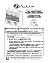
PRODUCT IDENTIFICATION
UNPACKING
1. Remove heater from carton.
2. Remove all protective packaging applied
to heater for shipping
Figure 1 - Vent-Free Gas Heater
Control Knob
Ignitor
Button
Front
Panel
Grill
Burner
Heater Cabinet
3. Check heater for any shipping damage. If
heater is damaged, promptly inform dealer
where you bought heater.
Water vapor is a by-product of gas combus-
tion. An unvented room heater produces ap-
proximately one (1) ounce (30 mL) of water for
every 1,000 BTUs (0.3 KWs) of gas input per
hour. Unvented room heaters are recommended
as supplemental heat (a room) rather than a
primary heat source (an entire house). In most
supplemental heat applications, the water vapor
does not create a problem. In most applications,
the water vapor enhances the low humidity
atmosphere experienced during cold weather.
The following steps will help ensure that water
vapor does not become a problem.
1. Be sure the heater is sized properly for the
application, including ample combustion
air and circulation air.
2. If high humidity is experienced, a dehu-
midier may be used to help lower the
water vapor content of the air.
3. Do not use an unvented room heater as
the primary heat source.
WATER VAPOR: A BY-PRODUCT OF
UNVENTED ROOM HEATERS

www.usaprocom.com
200218-01C8
AIR FOR COMBUSTION AND VENTILATION
WARNING: This heater shall
not be installed in a conned
space or unusually tight con-
struction unless provisions are
provided for adequate combus-
tion and ventilation air. Read the
following instructions to insure
proper fresh air for this and other
fuel-burning appliances in your
home.
Today’s homes are built more energy efcient
than ever. New materials, increased insulation
and new construction methods help reduce
heat loss in homes. Home owners weather
strip and caulk around windows and doors
to keep the cold air out and the warm air in.
During heating months, home owners want
their homes as airtight as possible.
While it is good to make your home energy
efcient, your home needs to breathe. Fresh
air must enter your home. All fuel-burning ap-
pliances need fresh air for proper combustion
and ventilation.
Exhaust fans, replaces, clothes dryers and
fuel burning appliances draw air from the
house to operate. You must provide adequate
fresh air for these appliances. This will insure
proper venting of vented fuel-burning appli-
ances.
WARNING: This heater shall
not be installed in a room or
space unless the required vol-
ume of indoor combustion air
is provided by the method de-
scribed in the National Fuel Gas
Code, ANSI Z223.1/NFPA 54, the
International Fuel Gas Code, or
applicable local codes.
WARNING: If the area in which
the heater may be operated does
not meet the required volume for
indoor combustion air, combus-
tion and ventilation air shall be
provided by one of the methods
described in the National Fuel
Gas Code, ANSI Z223.1/NFPA 54,
the International Fuel Gas Code,
or applicable local codes.

www.usaprocom.com
9200218-01C
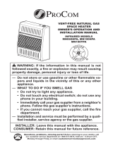
AIR FOR COMBUSTION AND VENTILATION
Outlet
Air
Ventilated
Attic
Outlet
Air
Inlet
Air
Inlet Air
Ventilated
Crawl Space
To
Crawl
Space
To Attic
Figure 2 - Ventilation Air from Inside
Building
Figure 3 - Ventilation Air from Outdoors
Note: Not for use in bedrooms or bathrooms.
Or
Remove
Door into
Adjoining
Room,
Option 3
Ventilation Grills
Into Adjoining Room,
Option 2
12"
12"
Ventilation
Grills into
Adjoining
Room,
Option 1
Ventilation Air From Inside Building
This fresh air would come from an adjoining
unconned space. When ventilating to an
adjoining unconned space, you must provide
two permanent openings: one within 12" of the
ceiling and one within 12" of the oor on the
wall connecting the two spaces (see options
1 and 2, Figure 2). You can also remove door
into adjoining room (see option 3, Figure 2).
Follow the National Fuel Gas Code, ANSI
Z223.1/NFPA 54, Air for Combustion and
Ventilation for required size of ventilation
grills or ducts.
VENTILATION AIR
Ventilation Air From Outdoors
Provide extra fresh air by using ventilation
grills or ducts. You must provide two perma-
nent openings: one within 12" of the ceiling
and one within 12" of the oor. Connect these
items directly to the outdoors or spaces open
to the outdoors. These spaces include attics
and crawl spaces. Follow the National Fuel
Gas Code, ANSI Z223.1/NFPA 54, Air for
Combustion and Ventilation for required size
of ventilation grills or ducts.
IMPORTANT: Do not provide openings
for inlet or outlet air into attic if attic has a
thermostat-controlled power vent. Heated air
entering the attic will activate the power vent.
Rework worksheet, adding the space of the
adjoining unconned space. The combined
spaces must have enough fresh air to supply
all appliances in both spaces.

www.usaprocom.com
200218-01C10
INSTALLATION
NOTICE: This heater is intended
for use as supplemental heat.
Use this heater along with your
primary heating system. Do not
install this heater as your pri-
mary heat source. If you have a
central heating system, you may
run system’s circulating blower
while using heater. This will help
circulate the heat throughout the
house. In the event of a power
outage, you can use this heater
as your primary heat source.
CAUTION: When installing
heater in a home garage
• heater pilot and burner must
be at least 18" above oor
• locate heater where moving
vehicle will not hit it
WARNING: A qualied ser-
vice person must install heater.
Follow all local codes.
WARNING: Never install the
heater
• in a bedroom or bathroom
• in a recreational vehicle
• where curtains, furniture,
clothing, or other ammable
objects are less than 36" from
the front, top, or sides of the
heater
• in high trafc areas
• in windy or drafty areas
Figure 4 - Mounting Clearances as
Viewed From Front of Heater
CAUTION: This heater cre-
ates warm air currents. These
currents move heat to wall sur-
faces next to heater. Installing
heater next to vinyl or cloth wall
coverings or operating heater
where impurities (such as to-
bacco smoke, aromatic candles,
cleaning uids, oil or kerosene
lamps, etc.) in the air exist, may
cause walls to discolor.
IMPORTANT: Vent-free heaters add moisture
to the air. Although this is benecial, installing
heater in rooms without enough ventilation air
may cause mildew to form too much moisture.
See Air for Combustion and Ventilation, pages
8 and 9.
CHECK GAS TYPE
Be sure your gas supply is right for your heat-
er. Otherwise, call dealer where you bought
the heater for proper type heater.
CLEARANCES TO
COMBUSTIBLES
Carefully follow the instructions below. This
heater is a freestanding unit designed to be
mounted on a wall or set on a base.
WARNING: Maintain the
minimum clearances shown
in Figure 4. If you can, provide
greater clearances from oor,
ceiling, and joining wall.
CEILING
36"
Minimum
8"
Minimum
From
Sides of
Heater
Left
Side
Right
Side
2" Minimum to Top Surface of Carpeting,
Tile or Other Combustible Material
FLOOR

www.usaprocom.com
11200218-01C
INSTALLATION
LOCATING HEATER
This heater is designed to be mounted on a
wall. For convenience and efciency, install
heater:
1. Where there is easy access for operation,
inspection, and service.
2. In the coldest part of room.
FASTENING HEATER TO WALL
Mounting Bracket
The mounting bracket is located on back panel
of heater (see Figure 5). It has been taped
there for shipping. Remove mounting bracket
from back panel.
Figure 5 - Mounting Bracket Location
Removing Front Panel of Heater
1. Remove two screws near bottom corners
of lower front panel.
2. Pull bottom of lower front panel forward,
then down (see Figure 6).
Figure 6 - Removing Front Panel Of
Heater
Methods For Attaching Mounting
Bracket To Wall
Use only the last hole on each end of mount-
ing bracket to attach bracket to wall. Attach
mounting bracket to a wall only in one of two
ways:
1. Attaching to wall stud: This method pro-
vides the strongest hold. Insert mounting
screws through mounting bracket and into
wall studs.
2. Attaching to wall anchor: This method
allows you to attach mounting bracket to
hollow walls (wall areas between studs)
or to solid walls (concrete or masonry).
Decide which method better suits your needs.
Either method will provide a secure hold for
the mounting bracket.
Marking Screw Locations
1. Tape mounting bracket to wall where
heater will be located. Make sure mount-
ing bracket is level.
WARNING: Maintain minimum
clearances shown in Figure
4, page 10. If you can, provide
greater clearances from oor and
joining wall.
2. Mark screw locations on wall (see Figure
7). Note: Mark only last hole on each end
of mounting bracket. Insert mounting
screws through these holes only.
3. Remove tape and mounting bracket from
wall.
Attaching Mounting Bracket To Wall
Note: Wall anchors, mounting screws, and
spacers are in hardware package. The hard-
ware package is provided with heater.
Attaching to Wall Stud Method
For attaching mounting bracket to wall studs:
1. Drill holes at marked locations using 9/64"
drill bit.
2. Place mounting bracket onto wall. Line
up last hole on each end of bracket with
holes drilled in wall.
3. Insert mounting screws through bracket
and into wall studs.
4. Tighten screws until mounting bracket is
rmly fastened to wall studs.
Mounting Bracket

www.usaprocom.com
200218-01C12
INSTALLATION
12
1
/8"
14
1
/2"
Min.
6
3
/4"
Min.
Adjoining Wall
Only Insert Mounting
Screws Through Last
Hole On Each End
Floor
10
5
/
8
"
Min.
17
3
/
8
"
18
1
/
2
"
Min.
Only Insert Mounting
Screws Through Last
Hole On Each End
Floor
Adjoining Wall
Figure 7 - Mounting Bracket Clearances
Model: MNSD2TPA
Models:
MNSD3TPA, MNSD5TPA
MNSD3TPA-BB, MNSD5TPA-BB
Figure 8 - Folding Anchor
Figure 9 - Popping Open Anchor Wings
For Thin Walls
Attaching to Wall Anchor Method
For attaching mounting bracket to hollow
walls (wall areas between studs) or solid walls
(concrete or masonry):
1. Drill holes at marked locations using
5/16" drill bit. For solid walls (concrete or
masonry), drill at least 1" deep.
2. Fold wall anchor as shown in Figure 8.
3. Insert wall anchor (wings rst) into hole.
Tap anchor ush to wall.
4. For thin walls (1/2" or less), insert red key
into wall anchor. Push red key to “pop”
open anchor wings (see Figure 9).
IMPORTANT: Do not hammer anchor key! For
thick walls (over 1/2" thick) or solid walls, do
not pop open wings.
5. Place mounting bracket onto wall. Line up
last hole on each end of bracket with wall
anchors.
6. Insert mounting screws through bracket
and into wall anchors.
7. Tighten screws until mounting bracket is
rmly fastened to wall.
Placing Heater On Mounting
Bracket
1. Locate two horizontal slots on back panel
of heater (see Figure 10).
2. Place heater onto mounting bracket. Slide
horizontal slots onto stand-out tabs on
mounting bracket.
Figure 10 - Mounting Heater Onto
Mounting Bracket
Mounting
Bracket
(attached
to wall)
Horizontal Slots
Stand-Out Tab

www.usaprocom.com
13200218-01C
INSTALLATION
Installing Bottom Mounting Bracket
1. Install bottom bracket to heater bottom
with two screws. It may be more conve-
nient to remove heater from wall bracket
to attach.
2. Place heater on wall mounting bracket.
3. Mark screw locations on wall.
4. Remove heater from mounting bracket.
5. If installing bottom mounting screws into
hollow or solid wall, install wall anchors.
Follow steps 1 through 4 under Attaching
To Wall Anchor Method, page 12. If install-
ing bottom mounting screw into wall stud,
drill holes at marked locations using 9/64"
drill bit.
Figure 11 - Installing Bottom Mounting Screws
6. Replace heater onto mounting bracket.
7. Place spacers between bottom mounting
holes and wall anchor or drilled hole.
8. Hold spacer in place with one hand. With
other hand, insert mounting screw though
bottom mounting hole and spacer. Place
tip of screw in opening of wall anchor or
drilled hole.
9. Tighten both screws until heater is rmly
secured to wall. Do not over tighten.
Note: Do not replace front panel at this time.
Replace front panel after making gas connec-
tions and checking for leaks.
Wall
Spacer
Heater
Side View
Front View
10,000 Btu
Front View
20,000 Btu or 30,000 Btu
Figure 12 - Installing Base Feet
INSTALLATION OF BASE STAND
(If Equipped)
Base Feet
Sheet Metal Screws
Before installing heater to base, please make
sure you have a hardware packet that con-
tains the following items:
2 - Base Feet
4 - Sheet Metal Screws
1. Carefully lay heater on its back on a table
with the bottom of the heater extending
outside the table edge.
2. Attach base feet to heater using sheet
metal screws.

www.usaprocom.com
200218-01C14
INSTALLATION
Figure 13 - Bottom of Heater
Yellow Natural Gas
Plunger Underneath
Metal Cap
Blue Propane/LP Gas
Plunger Underneath
Dust Cover
Figure 14 - Gas Regulator
Insert Gas Fitting
for Natural Gas
Insert Gas Fitting
for Propane/LP Gas
GAS SELECTION
This appliance is factory
preset for propane/LP gas.
No changes are required for
connecting to propane/LP.
Only a qualied installer or service
technician can perform gas selec-
tion and connecting to gas supply.
CAUTION: Two gas line in-
stallations at the same time are
prohibited.
CAUTION: To avoid gas leak-
age for the gas not being used at
the inlet of regulator, a qualied
installer or service technician
must use supplied cap.
You will notice a color coded
plunger on the inside of the regu-
lator. This is normal. When the in-
let connection tting is inserted
and tightened, this plunger will
be pushed back by the tting
making all of the adjustments
for the gas being supplied. DO
NOT REMOVE THE PLUNGER.
The regulator will not work.
The inlet regulator is color coded
for identication of the correct
gas type. Blue is for propane (LP
gas) and yellow is for natural gas.
Blue Dust Cover
DO NOT REMOVE
Blue Propane/LP
Plunger
Install Gas Fitting Here
FOR PROPANE/LP GAS
INSTALLATION: BLUE
1. Remove blue dust cover.
NG
LPG
INLET GAS PRESSURE
MAX 1/2 PSIG (3.5 KPA)
Gas Connection

www.usaprocom.com
15200218-01C
INSTALLATION
DO NOT use an off the shelf 3/8"
NPT pipe plug. This will damage
the plungers located inside the
regulator.
DO NOT try to remove the plung-
ers from inside the regulator. The
plunger will be pushed back as
the tting is installed.
Make sure the type of gas being
used is correct. Check to make
sure the connection tting is in
the correct inlet on the regula-
tor. Refer to Connecting to Gas
Supply, page 16.
If you are using natural gas
and the pilot will not light, see
Troubleshooting, page 24.
Use only the cap supplied on the
regulator. Do not use an off the
shelf pipe plug. This can damage
the plunger. The supplied regula-
tor cap is designed so it will not
engage the unused gas type.
4. Apply thread sealant to the threads on
the connection tting. While pushing in,
rotate the tting clockwise until the threads
engage the regulator. After the tting has
been hand tightened into the regulator
use a wrench to complete tightening of the
tting. Install additional tting to connect
to the house supply.
Blue Dust Cover
Metal Cap
Metal Cap
DO NOT REMOVE
Yellow Natural Gas Plunger
Install Gas Fitting Here
2. Apply thread sealant to the threads on
the connection tting. While pushing in,
rotate the tting clockwise until the threads
engage the regulator. After the tting has
been hand tightened into the regulator
use a wrench to complete tightening of the
tting. Install additional tting to connect
to the house supply.
FOR NATURAL GAS (NG)
INSTALLATION: YELLOW
1. Remove the blue dust cover from the
regulator.
2. Remove the metal cap installed over the
NG regulator inlet.
3. Install metal cap over LP/Propane regulator
inlet. This will keep debris out of regulator.
Fitting
supplied
by installer,
may vary.

www.usaprocom.com
200218-01C16
INSTALLATION
CONNECTING TO GAS SUPPLY
WARNING: A qualied ser-
vice technician must connect
heater to gas supply. Follow all
local codes.
WARNING: This appliance
requires a 3/8" NPT (National
Pipe Thread) inlet connection to
the pressure regulator.
WARNING: For natural gas,
Never connect heater to private
(non-utility) gas wells. This gas
is commonly known as wellhead
gas.
WARNING: Do not over-
tighten gas connections.
CAUTION: Use only new,
black iron or steel pipe. Inter-
nally tinned copper tubing may
be used in certain areas. Check
your local codes. Use pipe of
1/2" diameter or greater to allow
proper gas volume to heater. If
pipe is too small, undue loss of
pressure will occur.
CAUTION: For propane/
LP gas, never connect heater
directly to the gas supply. This
heater requires an external
regulator (not supplied). Install
the external regulator between
the heater and gas supply. Gas
supplier provides external regu-
lator for natural gas. The installer
provides the external regulator
for propane/LP gas.
CAUTION: For natural gas,
check your gas line pressure
before connecting heater to gas
line. Gas line pressure must be
no greater than 9.5" of water. If
gas line pressure is higher, heater
regulator damage could occur.
CAUTION: Avoid damage to
regulator. Hold gas regulator
with wrench when connecting
into gas piping and/or ttings.
CAUTION: Use pipe joint
sealant that is resistant to gas
(Propane/LP or Natural Gas).
Before installing heater, make sure you have
the items listed below:
• external regulator for propane/LP unit only
(supplied by installer)
• piping (check local codes)
• sealant (resistant to natural gas and pro-
pane/LP gas)
• equipment shutoff valve*
• test gauge connection*
• sediment trap
• tee joint
• pipe wrench
• exible gas hose (check local codes)
* A CSA design-certied equipment shutoff
valve with 1/8" NPT tap is an acceptable al-
ternative to test gauge connection. Purchase
the optional CSA design certied equipment
shutoff valve from your dealer.
Typical Inlet Pipe Diameters
Use 3/8" black iron pipe or greater. Installa-
tion must include an equipment shutoff valve,
union, and plugged 1/8" NPT tap. Locate NPT
tap within reach for test gauge hook up. NPT
tap must be upstream from heater (see Figure
15, page 17).
IMPORTANT: Install an equipment shutoff
valve in an accessible location. The equip-
ment shutoff valve is for turning on or shutting
off the gas to the appliance.

www.usaprocom.com
17200218-01C
CHECKING GAS CONNECTIONS
WARNING: Test all gas piping
and connections for leaks after
installing or servicing. Correct
all leaks at once.
WARNING: Never use an
open ame to check for a leak.
Apply a mixture of liquid soap
and water to all joints. If bubbles
form, there is a leak. Correct all
leaks at once.
Pressure Testing Gas Supply Piping System
Test Pressures In Excess Of 1/2 PSIG (3.5 kPa)
1. Disconnect heater with its appliance main
gas valve (control valve) and equipment
shutoff valve from gas supply piping sys-
tem. Pressures in excess of 1/2 PSIG will
damage heater regulator.
2. Cap off open end of gas pipe where equip-
ment shutoff valve was connected.
3. Pressurize supply piping system by either
opening propane/LP supply tank valve
for propane/LP gas or opening main gas
valve located on or near gas meter for
natural gas or using compressed air.
INSTALLATION
Figure 15 - Gas Connection
* Purchase the optional CSA design-certied equipment
shutoff valve from your dealer.
Apply pipe joint sealant lightly to male threads.
This will prevent excess sealant from going
into pipe. Excess sealant in pipe could result
in clogged heater valves.
For propane/LP gas, t
he installer must supply
an external regulator. The external regulator
will reduce incoming gas pressure. You must
reduce incoming gas pressure to between 11"
and 14" of water. If you do not reduce incom-
ing gas pressure, heater regulator damage
could occur. Install external regulator with
Figure 16 - External Regulator
with Vent Pointing Down
External
Regulator with
Vent Pointing
Down
Propane/LP
Supply Tank
Equipment
Shutoff Valve
Ground
Joint Union
3/8" NPT
Pipe Nipple
Tee Joint
Reducer
Bushing to
1/8" NPT
1/8" NPT
Plug Tap
Test Gauge
Connection*
Sediment
Trap
Tee Joint
Pipe Nipple
Gap
3" Minimum
the vent pointing down as shown in Figure
16. Pointing the vent down protects it from
freezing rain or sleet.
Install sediment trap in supply line as shown
in Figure 15. Place sediment trap where it is
within reach for cleaning. Place sediment trap
where trapped matter is not likely to freeze.
A sediment trap traps moisture and contami-
nants. This keeps them from going into heater
controls. If sediment trap is not installed or is
installed wrong, heater may not run properly.
Natural Gas
From Gas
Meter (7" W.C.
to 9.5" W.C.
Pressure)
Propane/LP
From External
Regulator (11" W.C.
to 14" W.C. Pressure)

www.usaprocom.com
200218-01C18
Figure 17 - Equipment Shutoff Valve
Open
Closed
Equipment
Shutoff Valve
Test Pressures Equal To or Less Than 1/2 PSIG (3.5 kPa)
1.
Close equipment shutoff valve (see Fig-
ure 17).
2. Pressurize supply piping system by either
opening propane/LP supply tank valve
for propane/LP gas or opening main gas
valve located on or near gas meter for
natural gas or using compressed air.
3. Check all joints from gas meter (natural
gas installations, see Figure 18) or from
propane/LP tank (propane/LP gas installa-
tions, see Figure 19) to equipment shutoff
valve. Apply a noncorrosive leak detection
uid to all joints. If bubbles form, there is
a leak.
4. Correct all leaks at once.
LP REGULATOR INSTALL 2
Figure 19 - Propane/LP Fuel Supply
Propane/LP
Supply Tank
Gas Valve
Equipment
Shutoff Valve
Figure 18 - Natural Gas Supply
Gas Meter
Gas Valve
Equipment
Shutoff Valve
PRESSURE TESTING HEATER GAS CONNECTIONS
1.
Open equipment shutoff valve (see Fig-
ure 17).
2. For natural gas open main gas valve lo-
cated on or near gas meter. For propane/
LP gas open propane/LP supply tank valve.
3. Make sure control knob of heater is in the
OFF position.
4. Check all joints from equipment shutoff
valve to control valve (see Figure 18 or
19).
Apply a noncorrosive leak detection
uid to all joints.
Bubbles forming show a
leak.
5. Correct all leaks at once.
6. Light heater (see Operation, page 19).
Check all other internal joints for leaks.
7. Turn off heater (see To Turn Off Gas Ap-
pliance, page 20).
8. Replace lower front panel.
4. Check all joints of gas supply piping sys-
tem. Apply a noncorrosive leak detection
uid to all joints. If bubbles form, there may
be a leak.
5. Correct all leaks at once.
6. Reconnect heater and equipment shutoff
valve to gas supply. Check reconnected
ttings for leaks.
INSTALLATION

www.usaprocom.com
19200218-01C
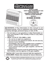
Figure 20 - Control Knob in the OFF
Position
1. STOP! Read the safety information above.
2. Make sure equipment shutoff valve is fully
open.
3. Turn control knob clockwise to the
OFF position.
4. Wait ve (5) minutes to clear out any air.
Then smell for gas, including near the
oor. If you smell gas, STOP! Follow "B"
in the safety information above. If you do
not smell gas, go to the next step.
5. Turn control knob counterclockwise
to the PILOT position. Press in control
knob for ve (5) seconds (see Figure 20).
Note: The rst time that the heater is oper-
ated after connecting the gas supply,the
control knob should be pressed for about
thirty (30) seconds. This will allow air to
bleed from the gas system. If pilot does
not stay lit, refer to Troubleshooting, pages
24 though 27. Also contact a qualied
service technician or gas supplier for
repairs. Until repairs are made, light pilot
with match.
• If control knob does not pop up when
released, contact a qualified service
technician or gas supplier for repairs.
6. With control knob pressed in, push
down and release ignitor button. This
will light pilot. The pilot is attached to
the front of burner. The pilot can be
seen through the grill. If needed, keep
pressing ignitor button until pilot lights.
Note: If pilot does not stay lit, refer to
Troubleshooting, pages 24 though 27.
Also contact a qualied service technician
or gas supplier for repairs. Until repairs
are made, light pilot with match. To light
pilot with match, see Manual Lighting
Procedure, page 20.
7. Keep control knob pressed in for 30
seconds after lighting pilot. After 30
seconds, release control knob. If control
knob does not pop up when released,
contact a qualied service technician or
gas supplier for repairs.
LIGHTING INSTRUCTIONS
Ignitor Button
Control Knob
OPERATION
FOR YOUR SAFETY READ BEFORE LIGHTING
WARNING: If you do not fol-
low these instructions exactly, a
re or explosion may result caus-
ing property damage, personal
injury or loss of life.
A. This appliance has a pilot which must
be lighted by hand. When lighting the
pilot, follow these instructions exactly.
B. BEFORE LIGHTING smell all around the
appliance area for gas. Be sure to smell
next to the oor because some gas is
heavier than air and will settle on the oor.
WHAT TO DO IF YOU SMELL GAS
• Do not try to light any appliance.
• Do not touch any electric switch; do
not use any phone in your building.
• Immediately call your gas supplier
from a neighbor’s phone. Follow the
gas supplier’s instructions.
• If you cannot reach your gas supplier,
call the re department.
C. Use only your hand to push in or turn
the gas control knob. Never use tools.
If the knob will not push in or turn by
hand, don’t try to repair it, call a qualied
service technician. Force or attempted
repair may result in a re or explosion.
D. Do not use this appliance if any part
has been under water. Immediately call
a qualied service technician to inspect
the appliance and to replace any part of
the control system and any gas control
which has been under water.

www.usaprocom.com
200218-01C20
Figure 21 - Burner Patterns
THERMOSTAT CONTROL OPERATION
TO TURN OFF GAS TO APPLIANCE
Shutting Off Heater
Turn control knob clockwise to the
OFF position.
Shutting Off Burner Only (pilot
stays lit )
Turn control knob clockwise to the
PILOT position.
OPERATION
Note: If pilot goes out, repeat steps 3
through 7. This heater has a safety inter-
lock system. Wait one (1) minute before
lighting pilot again.
8. Turn control knob counterclockwise
to desired heating level. The main burner
should light. Set control knob to any heat
level between 1 and 5.
CAUTION: Do not try to ad-
just heating levels by using the
equipment shutoff valve.
WARNING: If input gas type is
NG, make sure NG pilot burner ig-
nites. If input gas type is LP, make
sure LP pilot burner ignites.
MANUAL LIGHTING PROCEDURE
1. Remove lower front panel.
2. Follow steps 1 through 5 under Lighting
Instructions, page 19.
3. With control knob pressed in, strike match.
Hold match to pilot until pilot lights.
4. Keep control knob pressed in for 30 sec-
onds after lighting pilot. After 30 seconds,
release control knob. Follow step 8 under
Lighting Instructions, page 19.
5. Replace lower front panel.
Figure 22 - Pilot Assembly
OFF
Control Knob
MNSD2TPA
MNSD3TPA
MNSD3TPA-BB
MNSD5TPA
MNSD5TPA-BB
Burners on HIGH
Burners OFF
The thermostatic control used on this model
differs from standard thermostats. You set
standard thermostats to a specic tempera-
ture such as 72 degrees. The thermostat
used on this heater senses the room tem-
perature. At times the room may exceed the
set temperature. If so, the burner will shut
off. The burner will cycle back on when room
temperature drops below the set temperature.
The control knob can be set to any comfort
level between HIGH (5) and LOW (1).
Note: The thermostat sensing bulb reacts
to the temperature depending on housing
construction.
Pilot Air
Inlet Hole
Natural Gas
Burner
Propane/LP
Gas Burner
Thermocouple
Pilot Air Inlet Hole
Ignitor
Electrode
/