ROTRONIC AG, CH-8303 Bassersdorf
Tel. +41 44 838 11 44, www.rotronic.com
ROTRONIC Messgeräte GmbH, D-76275 Ettlingen
Tel. +49 7243 383 250, www.rotronic.de
ROTRONIC SARL, 56, F - 77600 Bussy-Saint-Georges
Tél. +33 1 60 95 07 10, www.rotronic.fr
ROTRONIC Italia srl, I- 20157 Milano
Tel. +39 2 39 00 71 90, www.rotronic.it
ROTRONIC Instruments (UK) Ltd, West Sussex RH10 9EE
Phone +44 1293 571000, www.rotronic.co.uk
ROTRONIC Instrument Corp, NY 11788, USA
Phone +1 631 427-3898, www.rotronic-usa.com
ROTRONIC Canada Inc.,Canada L8W 3P7
Phone + 1 905 754-5164, www.rotronic.ca
ROTRONIC Instruments Pte. Ltd., Singapore 159836
Phone +65 6376 2107, www.rotronic.sg
ROTRONIC Shanghai Rep. Office, Shanghai 200233, China
Phone +86 10 8225 4372, www.rotronic.cn
ROTRONIC Japan, Tokyo 180-0006, Japan
Phone +81 422 502 600, www.rotronic.com
12.1126.0101D
KURZBEDIENUNGSANLEITUNGSHORT INSTRUCTION MANUAL
Allgemeine Beschreibung
Herzliche Gratulation zum Kauf des RMS-Digital-
Eingang-Modules RMS-DI-L-R. Der Datenlogger verfügt
über einen internen Datenspeicher von 70’000
Messwerten und übermittelt diese kontinuierlich
per Ethernet an die RMS-Software. Diese Kurzbedie-
nungsanleitung beschreibt die wichtigsten Funktionen
des Gerätes.
Bitte lesen Sie diese Kurzbedienungsanleitung und die Betriebsanleitung auf
www.rotronic.com/rms sorgfältig durch.
Inbetriebnahme
Das Gerät wird automatisch mit Spannung versorgt, sobald die Batterie eingesetzt ist. Zusätzlich
muss das Modul mit 24V oder PoE versorgt werden, damit die Daten via Ethernet auf den Webservice
übertragen werden können. Der Datenlogger lässt sich einfach auf einer DIN-Schiene (EN50022 /
35mm x 7.5mm) befestigen. Beachten Sie die maximale Kabellänge der Eingangsseite (den tech-
nischen Daten zu entnehmen). Die Verbindung mit der RMS-Software wird per Pairing hergestellt.
Wichtig: Port80, DHCP
Für die Einbindung des Gerätes muss der Port 80 in ihrem Netzwerk freigeschaltet sein und ein
DHCP-Server muss die IP-Adresse an das Gerät zuweisen.
General description
Congratulations on your new RMS digital input module
RMS-DI-L-R. The data logger has an internal data me-
mory of 70,000 measured values and transmits these
values continuously to the RMS software by Ethernet.
These short instructions describe the main functions
of the device.
Please read this short manual and the instruction manual on www.rotronic.com/rms
carefully.
Commissioning
The device is supplied with power as soon as the battery is inserted. The module must additionally
be supplied with 24 V or PoE to be able to transmit data to the web service via Ethernet. The data
logger can be mounted easily on a DIN rail (EN 50022 / 35 mm x 7.5 mm). Note the maximum
cable length on the input side (see the technical data). The device is connected to the RMS soft-
ware by pairing.
Important: Port 80, DHCP
To integrate the device, port 80 must be enabled in your network and a DHCP server must assign
the IP address to the device.
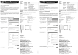
DIGITALES EINGANGSMODUL: RMS-DI-L-R
Einbinden des Eingangsmodul (Pairing) in 6 Schritten.
Integration of the input module (pairing) in 6 steps.
(1) Falls das Gerät nicht mit der Rotronic Cloud verbunden werden soll, muss der Server im Gerät
eingestellt werden.
a. GerätmitdemlokalenNetzwerkverbindenundRMS-Cong-Softwarestarten.
b. Gerät suchen unter
Gerät > Suchen > Netzwerkgerät
.DieSoftwarendetalleRMS-Geräte
im lokalen Netzwerk.
c. Unter Einstellungen den
Host
(Adresse des Servers) und die
URL
des Software-Services
angeben.
d.Kongurationabschliessen
mit
Schreiben.
(2) Einloggen in die RMS-Software /
Cloud. Unter
Extras > Setup >
Geräte > Neu
LAN-Gerät
(3) Seriennummer des Gerätes
eingeben.
(4) Knopf am Gerät kurz drücken.
LED blinkt kurz rot.
(5) Setzen Sie die gewünschten
Geräte-Einstellungen.
(6)Kongurationabschliessen.
(1)IfyoudonotwanttoconnectthedevicetotheRotronicCloud,theservermustbeconguredin
the device.
a. ConnectthedevicetothelocalnetworkandstarttheRMScongurationsoftware.
b. Search for the device under
Device > Search > Network Device
.ThesoftwarendsallRMS
devices in the local network.
c. Enter the
host
(server address)
and the URL of the software-
services under Settings.
d.Finishcongurationwith
Write
.
(2) Log into the RMS software /
cloud. Select Tools
> Setup >
Devices > New > LAN device
.
(3) Enter the serial number of the
device.
(4) Press the button on the device
briey.TheLEDashesred
briey.
(5)Congurethedevice.
(6)Finishconguration.
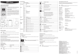
LED-Anzeige
Taste Modus Statusanzeige
Pairing
1s Bestätigt Pairing n x orange, die Anzeige blickt
während die Pairinganfrage offen ist
Gerätestatus anzeigen
1s In "online" Betrieb 1 x grün, Messung & Datenübertragung erfolgreich
1x orange, Messung erfolgreich, Datenübertragung
fehlgeschlagen
1x rot, Niedriger Batteriestand (nur bei Batteriebetrieb)
Automatisch Bei Zustandsänderung
am Eingang
Abmessungen / Anschlüsse
V+ Power Supply + D-IN1+
Eingang 1 Input (+ 5-24VDC)
V- Power Supply - D-IN2+R
Eingang 2 Reed
D-IN1+R
Eingang 1 Reed
D-IN2-
Eingang 2 GND
D-IN1-
Eingang 1 GND
D-IN2+
Eingang 2 Input (+ 5-24VDC)
Wartung
Abhängig vom Aufzeichnungsintervall, muss die Batterie regelmässig ausgetauscht werden.
Technische Daten:
Anzahl Eingänge 2 unabhängige digitale Eingänge
Eingangsfrequenz Max: 0.833Hz, bzw. 1.2s
Impulserkennung >100ms (periodisch > 1,2 sec.)
Input-Schaltung Logikpegel: 0V / 5-24V
Stromaufnahme Eingang 1/2 input <1mA
Reed-Schaltung Max. Last am Eingang: 100kΩ
Max. Kabellänge Eingänge <3m
Batterietyp RMS-BAT (2xAA, LiSocl2)
Spannungsversorgung
24 VDC ±10 % / <100 mA, PoE: 802.3af-2003, Klasse 1
Batterielebensdauer ~2 Jahre (bei 23 °C)
Mess- und Einsatzbereich -40…70 °C
Max. Einsatzhöhe 2000 m ü.M.
Speicherkapazität 70‘000 Messwertpaare
Log-Frequenz Event-basiert & Intervall
IP-Schutz IP20
Brandschutzklasse UL94-V0
Software RMS Monitoring-Software
Gewicht 200 g
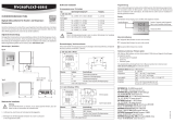
LED indicators
Button Mode Status
Pairing
1s Conrmspairing nxorange,theindicatorashes
while the pairing request is running
Show device status
1s at "online" operation 1 x green, measurement & data transmission succesful
1 x orange, measurement succesful, data transfer failed
1x red, low battery (only by battery powered)
Automatic at a status change from
the input
Dimensions / Connections
V+ Power Supply + D-IN1+ Input 1 Input (+ 5-24VDC)
V- Power Supply - D-IN2+R Input 2 Reed
D-IN1+R Input 1 Reed D-IN2- Input 2 GND
D-IN1- Input 1 GND D-IN2+ Input 2 Input (+ 5-24VDC)
Maintenance
The battery needs to be replaced regularly in dependence on the recording interval.
Technical data:
Number of inputs 2 independent digital inputs
Input frequency Max: 0.833Hz, bzw. 1.2s
Pulse recognition >100 ms (periodic > 1.2 sec.)
Input circuit Logic level: 0 V / 5-24 V
Current consumption Input 1/2 input <1mA
Reed circuit Max. load at input: 100kΩ
Max. cable length inputs <3m
Battery type RMS-BAT (2xAA, LiSocl2)
Power supply
24 VDC ±10% / <100 mA, PoE: 802.3af-2003, Class 1
Battery life ~ 2 years (at 23 °C)
Range of measurement / application -40…70 °C
Max. altitude 2000 m ASL
Storage capacity 70,000 data points
Log frequency Event-based & interval
IP protection IP20
Fire protection class UL94-V0
Software RMS Monitoring Software
Weight 200 g
12.1126.0101E
DIGITAL INPUT MODULE: RMS-DI-L-R

ROTRONIC AG, CH-8303 Bassersdorf
Tel. +41 44 838 11 44, www.rotronic.com
ROTRONIC Messgeräte GmbH, D-76275 Ettlingen
Tel. +49 7243 383 250, www.rotronic.de
ROTRONIC SARL, 56, F - 77600 Bussy-Saint-Georges
Tél. +33 1 60 95 07 10, www.rotronic.fr
ROTRONIC Italia srl, I- 20157 Milano
Tel. +39 2 39 00 71 90, www.rotronic.it
ROTRONIC Instruments (UK) Ltd, West Sussex RH10 9EE
Phone +44 1293 571000, www.rotronic.co.uk
ROTRONIC Instrument Corp, NY 11788, USA
Phone +1 631 427-3898, www.rotronic-usa.com
ROTRONIC Canada Inc.,Canada L8W 3P7
Phone + 1 905 754-5164, www.rotronic.ca
ROTRONIC Instruments Pte. Ltd., Singapore 159836
Phone +65 6376 2107, www.rotronic.sg
ROTRONIC Shanghai Rep. Office, Shanghai 200233, China
Phone +86 10 8225 4372, www.rotronic.cn
ROTRONIC Japan, Tokyo 180-0006, Japan
Phone +81 422 502 600, www.rotronic.com
12.1126.0101F
12.1126.0101I
MODULE NUMÉRIQUE D'ENTRÉE: RMS-DI-L-R MODULO DI INGRESSO DIGITALE: RMS-DI-L-R
MODE D’EMPLOI ABRÉGÉ MANUALE DI ISTRUZIONI BREVE
Description générale
Tous nos remerciements pour l’achat du module numé-
rique RMS d’entrée RMS-DI-L-R. Le logger de données
dispose d’une mémoire interne d’enregistrement pour
70’000 valeurs de mesure et retransmet celles-ci par
Internet, en continu, au logiciel RMS. Ce mode d’emploi
abrégé se limite à la description des fonctions essen-
tielles de cet appareil.
Veuillez lire attentivement ce bref manuel d'utilisation et les instructions d'utilisation
sur www.rotronic.com/rms par.
Mise en service
L’appareil est alimenté automatiquement, dès que la pile est mise en place. De plus, le module
doitêtrealimentéencourant24VouparPoE,anquelesdonnéespuissentêtretransmisespar
EthernetauserviceWeb.LeloggerdedonnéespeutêtrexéfacilementsurunrailDIN(EN50022/
35mm x 7,5mm). Respectez la longueur maximale des câbles du côté des entrées (à relever dans
les caractéristiques techniques). La liaison avec le logiciel RMS est effectuée par couplage.
Important: Port80, DHCP
And’intégrerl’appareil,leport80doitêtreactivésurvotreréseau,etunserveurDHCPdoitlui
attribuer une adresse IP.
Descrizione generale
Congratulazioni per l'acquisto del modulo di ingresso
digitale RMS RMS-DI-L-R. Il data logger dispone di una
memoria dati interna di 70.000 valori di misura, valori
che trasmette continuamente via Ethernet al software
RMS. Il presente manuale d'istruzioni breve descrive le
funzioni principali dello strumento.
Leggere attentamente questo breve manuale d'uso e le istruzioni per l'uso all'indirizzo
www.rotronic.com/rms.
Messa in servizio
Lo strumento riceve tensione automaticamente dopo l'inserimento della batteria. In più il modu-
lo necessita di alimentazione a 24 V o PoE, per poter trasmettere i dati via Ethernet al web service.
IldataloggerpuòesseressatosemplicementesuunabarraDIN(EN50022/35mmx7,5mm).
Considerarelalunghezzamassimadelcavoiningresso(specicataneidatitecnici).Ilcollega-
mento con il software RMS viene stabilito tramite pairing (associazione).
Importante: Porta 80, DHCP
Per l'associazione dello strumento la Porta 80 andrà attivata in rete e un server DHCP dovrà
assegnare allo strumento l'indirizzo IP.
Intégration du module d’entrée (couplage) en 6 étapes.
Come associare il modulo di ingresso (pairing) in 6 passaggi.
(1) Au cas où l’appareil ne doive pas être relié au Cloud Rotronic, son serveur interne doit être
paramétré.
a.Relierl’appareilauréseaulocaletdémarrerlelogicielRMS-Cong.
b. Rechercher l
’
appareil avec Appareil
> Rechercher > Appareil réseau
. Le logiciel trouve tous les
appareils RMS connectés au réseau local.
c. Entrer l’hôte (adresse du ser-
veur) et l’
URL
du service logi-
ciel dans Réglages.
d.Terminerlacongurationavec
Écrire
.
(2) Effectuer la connexion avec
le logiciel RMS / Cloud. Sous
Extras>Conguration>Appareil>
Nouveau
périphérique LAN
(3) Entrer le numéro de série de
l’appareil.
4) Presser la touche sur l’appareil.
Bref clignotement rouge.
(5) Effectuer les réglages appareil
souhaités.
(6) Terminerlaconguration.
(1) Se lo strumento non deve essere collegato al cloud Rotronic, occorre impostare il server nello
strumento.
a.CollegarelostrumentoallaretelocaleelanciareilsoftwaredicongurazioneRMS.
b.
Cercare lo strumento in Strumento > Cerca > Strumento di rete
. Il software individua tutti gli
strumenti RMS della rete locale.
c. In Impostazioni indicare
l'host (indirizzo del server) e
l'URL del servizio software.
d. Terminare la configurazione
con Scrivi
.
(2) Login nel software / cloud
RMS.
Seguire il percorso Extra >
Congurazione>Strumenti>
Nuovo Strumento LAN
(3) Digitare il numero di serie
dello strumento.
4) Premere brevemente il pulsante
sullo strumento. Il LED lampeggia
brevemente in rosso.
(5) Impostare lo strumento come
richiesto.
(6) Terminarelacongurazione.
Afchage LED
Touche Mode Afchage de l’état
Couplage
1s Conrmelecouplage nxorange,l’afchageclignotependantquelademandede
couplage est ouverte
Afcher l’état de l’appareil
1s opération "en ligne" 1 fois vert, mesure réussie et transfert de données
1 fois orange, mesure réussie, transfert de données échoué
1 fois rouge, batterie faible (seulement avec le fonctionne-
ment de la batterie)
Automatique Changement de
statut à l'entrée
Dimensions / Raccordements
V+ Alimentation + D-IN1+ Entrée 1 Input (+ 5-24VCC)
V- Alimentation - D-IN2+R Entrée 2 Reed
D-IN1+R Entrée 1 Reed D-IN2- Entrée 2 terre
D-IN1- Entrée 1 terre D-IN2+ Entrée 2 Input (+ 5-24VCC)
Entretien
Les piles doivent être changées régulièrement, selon l’intervalle d’enregistrement.
Caractéristiques techniques:
Nombre d’entrées 2 entrées numériques indépendantes
Fréquence d’entrée Max: 0,833Hz, resp. 1,2s
Reconnaissance d’impulsion >100ms (périodique > 1,2 sec.)
Circuit d’entrée Niveau logique: 0V / 5-24V
Consommation électrique Entrée 1/2 Input <1mA
Circuit Reed Charge max. en entrée: Max. 100kΩ
Longueur max. du câble des entrées <3m
Type de pile RMS-BAT (2xAA, LiSocl2)
Tension d’alimentation
24 VCC ±10 % / <100 mA, PoE: 802.3af-2003, classe 1
Longévité de la pile ~ 2 ans (à 23 °C)
Gammes de mesure et d’utilisation -40…70 °C
Altitude max. d’utilisation 2000 m au-dessus du niveau de la mer
Capacité mémoire 70’000 paires de valeurs de mesure
Fréquence d’enregistrement Selon les évènements et l’intervalle
Protection IP IP20
Classe de protection incendie UL94-V0
Logiciels Logiciel de monitoring RMS
Poids 200 g
Indicatore LED
Tasto Modalità Indicazione di stato
Pairing
1s Pairing confermato n volte arancione, l'indicatore lampeggia
mentre la richiesta di pairing è in corso
Indicazione di stato dello strumento
1s in modalità "online" 1 volta verde, misurazione & trasmissione dei dati con successo
1 volta arancione,misurando correttamente, la trasmissione dei
dati non è riuscita
1volta rosso,livello batteria basso (solo con il funzionamento
a batteria)
Automatica Al cambio di stato
all'ingresso
Dimensioni / connessioni
V+ Alimentatore + D-IN1+ Ingresso 1 input (+ 5-24 VDC)
V- Alimentatore - D-IN2+R Ingresso 2 reed
D-IN1+R Ingresso 1 reed D-IN2- Ingresso 2 GND
D-IN1- Ingresso 1 GND D-IN2+ Ingresso 2 Input (+ 5-24 VDC)
Manutenzione
La batteria deve essere regolarmente sostituita in base all'intervallo di registrazione.
Dati tecnici:
Numero di ingressi 2 ingressi digitali indipendenti
Frequenza di ingresso Max: 0,833Hz, resp. 1,2s
Riconoscimento impulsi >100 ms (periodico > 1,2 sec.)
Circuito di ingresso Livello logico: 0 V / 5-24 V
Consumo di corrente Ingresso 1/2 Input <1mA
Circuito reed Carico max. in ingresso: 100kΩ
Lunghezza cavo max. ingressi <3m
Tipo di batteria RMS-BAT (2xAA, LiSocl2)
Alimentazione
24 VCC ±10 % / <100 mA, PoE: 802.3af-2003, Classe 1
Durata delle batterie ~ 2 anni (à 23 °C)
Campo di misura e di lavoro -40…70 °C
Altitudine max. di impiego 2.000 m s.l.m.
Capacità di memoria 70.000 coppie di valori di misura
Frequenza di log In base all'evento e intervallo
Protezione IP IP20
Classe antincendio UL94-V0
Software Software di monitoraggio RMS
Peso 200 g
/


