1 © 2008 Extreme Networks, Inc. All rights reserved. Part Number 120390-00 Rev 03 2
Altitude 350-2i/350-2d AP Installation Instructions
Altitude 350-2i/350-2d AP Installation Instructions
Unpacking and mounting the Altitude Access Point (AP)
NOTE
For Altitude 350-2d, attach the antennas to the RP-SMA connectors in each side of the Altitude AP
before mounting on its bracket.
Security Note #2: To remove the Altitude AP, use a screwdriver to take out the rivet.
Connecting and powering the Altitude AP
WARNING!
This device must not be connected to a LAN segment with outdoor wiring. Ensure that all cables are
run correctly to avoid strain. Replace the power supply adapter immediately, if it shows any signs of
damage.
NOTE
Powering up the Altitude AP initiates its automatic discovery and registration process with the
Summit
®
WM Controller. The parameters for this process are explained in the Summit WM User Guide.
4 Power up the Altitude AP in one of three ways:
Power Over Ethernet (PoE)
If your network is already set up with PoE (802.3af compliant), plug in the Ethernet cable
to the RJ45 connector in the Altitude AP.
Power Over Ethernet: Adding PoE Injector
If your network is not set up with PoE, you can provide power to the ethernet cable with a
PoE injector. The PoE injector must be 802.3af compliant. The PoE injector is not provided
with the Altitude AP.
Power via External Power Adaptor
An AC adaptor is not provided with the Altitude AP.
Specifications: Input: 120-240 VAC, Output: 6VDC, 1.5 Amps max.
To use an adaptor, install the Altitude AP within six feet of a wall outlet, attach the
adaptor to the Altitude AP and then plug the adaptor into the wall outlet.
Use only a safety approved POE injector or a safety approved Limited Power Source (Class
2) AC adaptor.
NOTE
For installations that use Receive diversity (the default), the antennas should be pointed in the same
direction. For installations that do NOT use Receive diversity, or for those that split the 802.11a and
802.11b/g radio onto different physical ports, then the antennas can be pointed in whatever direction
is desired.
The Altitude
™
AP has two models:
• Altitude 350-2i: internal dual (multimode) diversity
antennas
• Altitude 350-2d: dual external antennas, RP-SMA
connectors
Unpack the Altitude AP from its carton. Also in the carton are:
• one wall mounting bracket
• 3 screws and 3 wall plugs
• one plastic rivet (to secure Altitude AP to bracket)
For Altitude 350-2d, the dual external antennas are also
included.
1 Mount the Altitude AP wall bracket,
using 3 screws. Mount it near the LAN
ethernet cable plug coming from the wall.
2 Press the back of the Altitude AP onto
the bracket, aligning it with the open
notches in the bracket. Then slide it down
until the security spring clip holds it in
place.
Security Note #1: To remove the Altitude AP,
release the spring clip by inserting an Allen
key (or other similar tool) into the small hole
at the bottom of the bracket. Then slide the
case up the bracket and lift off the Altitude
AP.
3 Using a screwdriver, insert the plastic rivet
through the hole at the bottom of the
bracket and into the Altitude AP case. This
locks the case to the bracket.
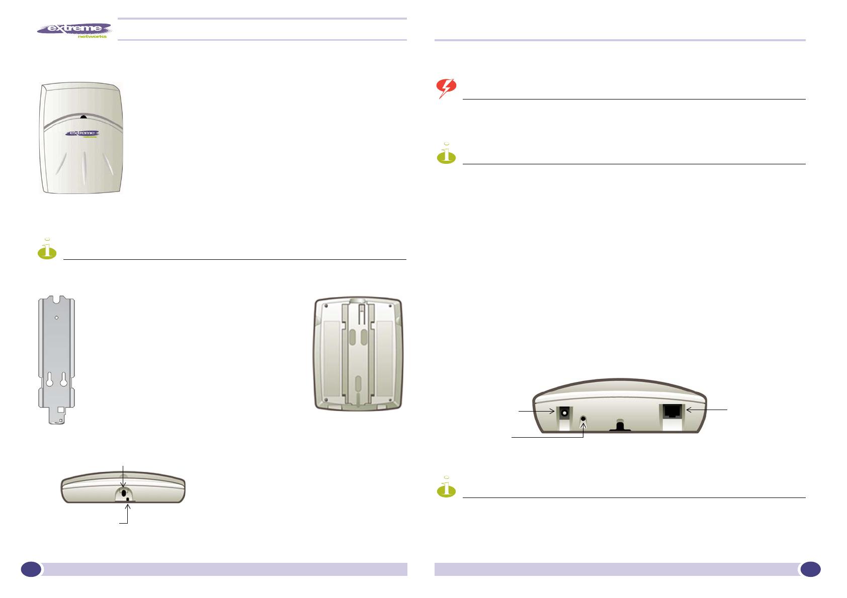
Opening for rivet
Opening for Allen key
Reset button
[Optional]. Plug in the
output of AC Power
Module (if PoE is not
being used in your
network).
Plug in the
Ethernet cable into
the RJ45 port.
