Page is loading ...

AVIS IMPORTANT AUX CONSOMMATEURS
Cette boîte contient l’unité de ventilation et son contrôle mural. Pour compléter le sys-
tème et en faire l’installation, vous devez vous procurer une autre boîte contentant
les pièces d’installation. Afin d’assurer votre entière satisfaction, les ingénieurs de
Venmar ont conçu et testé cet appareil avec les pièces d’origine Venmar.
L’utilisation de ces pièces de première qualité vous garantit le rendement optimal de l’appareil.
Les pièces des autres marques ne sont ni approuvées par Venmar ni conformes à nos normes de
qualité. Venmar décline donc toute responsabilité quant au bon rendement de ce produit s’il est
installé avec d’autres pièces.
MANUEL DE L’UTILISATEUR
Lisez et conservez ces instructions
Échangeur d’air modèle :
EA 20200, PRO 100, PRO 200
17/11/03 01506
IMPORTANT ADVICE TO CONSUMERS
This box contains the ventilation system and the wall control. In order to complete the
system and its installation, you have to get another box which contains the installa-
tion parts.To assure your entire satisfaction, Venmar’s engineers have developed and
tested this system with its original parts. We use top quality parts in order to guaran-
tee you the optimum efficiency of this system. Other brand parts are not approved by Venmar and
do not comply with our quality standards. Venmar accepts no responsibility regarding product effi-
ciency when installed with other parts than Venmar.
USER MANUAL
Read and save these instructions
Air exchanger model:
EA 20200, PRO 100, PRO 200
17/11/03 01506

1 WARRANTY . . . . . . . . . . . . . . . . . . . . . . . . . . . . . . . . . . . . . . 2
2 OPERATIONAL PRINCIPLES . . . . . . . . . . . . . . . . . . . . . . . . 3
3 WALL CONTROL . . . . . . . . . . . . . . . . . . . . . . . . . . . . . . . . . . 3
4 MAINTENANCE . . . . . . . . . . . . . . . . . . . . . . . . . . . . . . . . . . . 5
5 WARNING . . . . . . . . . . . . . . . . . . . . . . . . . . . . . . . . . . . . . . . 5
6 TROUBLESHOOTING . . . . . . . . . . . . . . . . . . . . . . . . . . . . . . 5
7 INSTALLATION . . . . . . . . . . . . . . . . . . . . . . . . . . . . . . . . . . . 6
The ventilation systems from VENMAR VENTILATION inc. are high-quality products manufactured
and packaged with great care. The length of the warranty is specified in your warranty document
included with your unit. If an operational defect occurs and cannot be resolved by reading this man-
ual, then we urge you to observe the following rules.
RULES TO FOLLOW:
If the unit is defective, call our nearest service centre (list included). Be sure to write down the seri-
al number before calling. This can be found on the sticker placed on the side of the unit. Our serv-
ice personnel will determine with you the reason for the defect and will help you find a solution to
your problem. Call VENMAR VENTILATION inc. at 1-800-567-3855 if you don’t succeed in contact-
ing a service centre.
BILL OF PURCHASE:
All repairs or replacements covered by the warranty require the original bill of purchase. Please
retain your original.
MISCELLANEOUS COSTS:
In each case, costs for the removal and installation of the unit will be charged to the customer.
CONDITIONS AND LIMITATIONS:
The above warranty applies to all cases where the damage is not a result of poor installation,
improper use, mistreatment or negligence, acts of God, or any other circumstances beyond the
control of VENMAR VENTILATION inc. Any repairs carried out without the supervision of VENMAR
VENTILATION inc. will automatically cancel the warranty. Furthermore, VENMAR VENTILATION
inc. will not be held responsible for any bodily injury or damage to personal property or real estate,
whether caused directly or indirectly by the ventilation system.
1. WARRANTY
TABLE OF CONTENTS
2
1 GARANTIE . . . . . . . . . . . . . . . . . . . . . . . . . . . . . . . . . . . . . . . 2
2 PRINCIPES DE FONCTIONNEMENT . . . . . . . . . . . . . . . . . . 3
3 CONTRÔLE MURAL . . . . . . . . . . . . . . . . . . . . . . . . . . . . . . . 3
4 ENTRETIEN . . . . . . . . . . . . . . . . . . . . . . . . . . . . . . . . . . . . . . 4
5 MISE EN GARDE . . . . . . . . . . . . . . . . . . . . . . . . . . . . . . . . . . 5
6 DÉPANNAGE . . . . . . . . . . . . . . . . . . . . . . . . . . . . . . . . . . . . . 5
7 INSTALLATION . . . . . . . . . . . . . . . . . . . . . . . . . . . . . . . . . . . 6
Les systèmes de ventilation de VENMAR VENTILATION inc. sont des produits de grande qualité,
fabriqués et emballés avec soin. Pour la durée de la garantie, voir la carte de garantie incluse avec
votre appareil. Si un problème de fonctionnement a lieu et ne peut pas être résolu en consultant ce
manuel, alors suivez la marche à suivre ci-dessous.
MARCHE À SUIVRE :
Si l’appareil s’avère défectueux, contacter le centre de service le plus près de chez vous (liste
ci-jointe). Prenez soin de noter le numéro de série avant d’appeler. On le trouve sur une étiquette
située sur le côté de l’appareil. Notre personnel de service déterminera avec vous la cause du
problème et vous aidera à trouver une solution. Contactez VENMAR VENTILATION inc. au numéro
1-800-567-3855 si vous ne réussissez pas à rejoindre un centre de service.
FACTURE :
Toute réparation ou tout remplacement couvert par la garantie nécessite la facture d’achat. Prenez
soin de bien la conserver.
FRAIS DIVERS :
Les frais d’enlèvement et d’installation de l’appareil seront, dans tous les cas, à la charge et à la
responsabilité du consommateur.
CONDITIONS ET LIMITES :
La garantie ci-dessus s’appliquera dans tous les cas où les dommages ne seront pas le résultat
d’une mauvaise installation, d’un mauvais usage, d’abus ou de négligence, de force majeure ou de
toute autre circonstance hors du contrôle de VENMAR VENTILATION inc. Tout travail de réparation
exécuté sans la supervision de VENMAR VENTILATION inc. annulera automatiquement la
garantie. De plus, VENMAR VENTILATION inc. ne sera pas tenue responsable des blessures
corporelles ou dommages à la propriété personnelle ou immobilière causés directement ou
indirectement par le système de ventilation.
1. GARANTIE
TABLE DES MATIÈRES
2

L’échangeur d’air est conçu pour éliminer les problèmes d’humidité excessive, pour uniformiser la
température et l’humidité et pour filtrer l’air ambiant de la maison. L’échangeur d’air effectue les
opérations suivantes :
CIRCULATION D’AIR : (PRO 200 SEULEMENT)
L’appareil fait circuler l’air à l’intérieur de la maison ce qui uniformise la température et l’humidité
de l’air ambiant.
CIRCULATION AVEC ÉCHANGE D’AIR :
Tout en faisant circuler l’air à l’intérieur,
l’appareil évacue une partie de l’air vicié et le
remplace par de l’air frais et sec provenant de
l’extérieur. Les bienfaits suivants sont ainsi
obtenus : réduction du taux d’humidité, élimina-
tion de l’air vicié, un air ambiant plus confor-
table durant les nuits chaudes de l’été.
FILTRATION :
Lorsque l’air circule dans l’appareil, un filtre
mécanique capte les poussières.
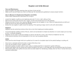
3.1 IDENTIFICATION DES COMPOSANTES
3.2 COMMENT UTILISER LE CONTRÔLE MURAL
a) Sélection du taux d’humidité :
Hiver : (température extérieure entre 5
o
C et -30
o
C)
– Placez le sélecteur vis-à-vis la valeur correspondante de la température extérieure (entre
50 % et 25 %).
– S’il y a des gouttes d’eau ou du givre dans les fenêtres, baissez de 1 à 2 % par 24 heures
jusqu’à ce que la condensation soit éliminée.
– Ne descendez pas plus bas que 25 % : l’air deviendra trop sec et nuira au confort des occu-
pants.
Printemps et Automne :
– Placez le sélecteur n’importe où entre 75 % et 50 % (plus haut les journées chaudes, plus
bas les journées froides).
–
Procédez selon les instructions pour « Hiver » si certaines périodes ressemblent plus à l’hiver !
3. CONTRÔLE MURAL
2. PRINCIPES DE FONCTIONNEMENT
3
sélecteur du taux d’humidité
sélecteur de circulation
symbole « Circulation intermittente »
symbole « Circulation continue »
The air exchanger is designed to eliminate problems of excessive humidity, to steady the temper-
ature and the humidity and to filter the air inside your house. The air exchanger carries out the fol-
lowing operations:
AIR CIRCULATIONS: (PRO 200 ONLY)
The system circulates the air inside the house,
thus steadying the temperature and the humid-
ity throughout.
CIRCULATION WITH AIR EXCHANGE:
While continually circulation the air within the
house, the unit also evacuates part of this stale
air and replaces it with fresh dry air from the
outside. The following extra benefits are thus
obtained: lowering of the humidity, elimination
of stale air, cooling of the house on hot summer
nights.
FILTRATION:
When the air flows through the system, a
mechanical filter traps dust particles.
3.1 IDENTIFICATION OF PARTS
3.2 HOW TO USE THE WALL CONTROL
a) Using the humidity level selector:
Winter: (outside temperature between 5
o
C and -30
o
C)
– Position the selector between 50% and 25%, pointing approximately to the corresponding
outside temperature.
– If there is condensation or frost on the windows, then lower the humidity level by 1 to 2%
every 24 hours until the condensation has evaporated.
– Do not go lower than 25%: the air will become too dry for human comfort.
3. WALL CONTROL
2. OPERATIONAL PRINCIPLES
3
humidity level selector
circulation selector
symbol for “Intermittent Circulation”
symbol for “Continuous Circulation”

Spring and Fall:
– Position the selector anywhere between 75% and 50% (higher on warm days, lower on cold
days).
– If certain periods during the spring and fall seem more like winter then you should follow the
instructions given for humidity control during the winter!
Summer:
– Position the selector at 80% during the day.
– If you want to introduce cool fresh air into the house during certain summer nights, then
lower the selector to 20% for these nights.
b) Explanations about humidity levels: (IMPORTANT!)
The comfort level for human beings is between 30% and 45% relative humidity. To measure the
present humidity level in your house, you can proceed as follows:
– turn the dial to 80%
– turn the dial slowly downwards until you hear a “click”. The dial will then be pointing to the
value for the present humidity level (precision of 5%).
Turning the selector lower than the “click” position means that you desire to lower the humidity level
in the house.This action will initiate the “air exchange” mode on your ventilation system and means
that you are expecting the stale humid air from inside to be replaced with dryer air from outside. It
is therefore pointless to try and lower the humidity with “air exchange” on rainy or foggy days.
Turning the selector higher than the “click” position means that you are not interested in having your
ventilation system function under “air exchange” mode.
Finally keep in mind that the instructions given above are just guidelines. You might prefer different
values for the humidity selector, depending on the insulation of your house, the type of windows, or
to satisfy the specific needs of certain occupants. After some experimenting, you will eventually
develop a control method best adapted to your household needs.
c) Using the circulation selector (Model PRO 200 only)
– “Continuous Circulation”: At the exact moment when the desired humidity level is
reached, the “air exchange” mode is interrupted and the system continues to operate under
“circulation” mode only (see section 2). The “air exchange” mode will be reactivated only if
the humidity level in the house goes up higher than the selected value.
– “Intermittent Circulation”: At the exact moment when the desired humidity level is
reached, the unit goes off. It will automatically start up again in “air exchange” mode if the
humidity level in the house goes up higher than the selected value.
– Recommendations for a PRO 200 installed in the basement: “Continuous Circulation” during
the winter; “Intermittent Circulation” during spring, summer, and fall.
– Warning: Adjust for “Continuous Circulation” during all 4 seasons if your unit is
installed in the attic.
3. WALL CONTROL (continued)
4
Été :
– Placez le sélecteur à 80 % pendant le jour.
– Si vous désirez introduire de l’air frais dans la maison durant certaines nuits, baissez le con-
trôle à 20 % pendnat ces nuits.
b) Explications sur les niveaux d’humidité : (IMPORTANT !)
La zone de confort de l’être humain se situe entre 30 % et 45 % d’humidité relative. Pour connaître
la valeur actuelle de l’humidité relative dans votre maison, vous devez procéder comme suit :
– Placez d’abord le sélecteur à 80 % d’humidité relative
– Ensuite tournez lentement le sélecteur vers la droite jusqu’au moment où vous entendrez un
« clic ». La position de ce « clic » correspond à la valeur actuelle de l’humidité relative (pré-
cision de 5 %).
Tourner ce contrôle plus bas que la position « clic » signifie que vous souhaitez baisser le niveau
d’humidité dans la maison. Cette action initiera le mode « échange d’air » de votre système de ven-
tilation et signifie que vous vous attendez à ce que votre air vicié soit remplacé par de l’air plus sec
de l’extérieur. Il est évident que vous ne réussirez pas à baisser le taux d’humidité dans la maison
par cette méthode si le temps est pluvieux ou brumeux à l’extérieur.
Tourner le contrôle plus haut que la position « clic » signifie que vous désirez arrêter l’échange de
l’air avec l’extérieur.
Finalement, les instructions ci-dessus sont offertes à titre de suggestions. Selon les types de
fenêtres, les types d’isolant et les besoins spécifiques de certains occupants, il se peut que vous
préfériez procéder différemment pour contrôler l’humidité. Le choix est vôtre et, avec un peu d’ex-
périmentation, vous trouverez l’équilibre désiré.
c) Le sélecteur de circulation (Modèle PRO200 seulement)
–«Circulation continue » : dès l’instant où le niveau d’humidité sélectionné est atteint, il y a
interruption du mode « échange d’air » et le système continue sous le mode « circulation »
seulement (voir section 2). Le mode « échange d’air » sera réactivé seulement si le niveau
d’humidité dans la maison dépasse la valeur sélectionnée.
– « Circulation intermittente » : dès l’instant où le niveau d’humidité sélectionné est atteint,
le système arrête de fonctionner. Il redémarre dans le mode « échange d’air » seulement si
le niveau d’humidité dans la maison dépasse la valeur sélectionnée.
– Recommandations pour un PRO 200 installé au sous-sol : « Circulation continue » pour l’hi-
ver; « Circulation intermittente » pour l’été, l’automne et le printemps.
– Mise en garde : Régler à « Circulation continue » durant les 4 saisons pour les
appareils installés à l’entretoit.
Filtre à air : Nous recommandons de le laver à tous les
trois mois. D’abord, passez l’aspirateur sur le filtre pour
enlevez les dépôts de poussière. Ensuite, nettoyez-le
dans une solution d’eau chaude et de savon.
Évents extérieurs : Nettoyer les grillages des
entrées/sorties extérieures au moins une fois par
année, préférablement à l’automne.
4. ENTRETIEN
3. CONTRÔLE MURAL (suite)
4

• Ne pas utiliser l’échangeur d’air pendant le sablage des joints de gypse ou lors de travaux
importants de rénovation. La poussière générée par ces activités peut endommager l’appareil.
• Ne pas utiliser l’échangeur d’air pendant tous travaux de vernissage. De plus, si votre appareil
est situé à l’entretoit, nous recommandons de boucher la grille d’aspiration d’air vicié et la grille
de distribution d’air frais. Les vapeurs de vernis peuvent endommager l’appareil.
• Pour les échangeurs d’air installés à l’entretoit, il est important de NE PAS METTRE
L’UNITÉ EN ARRÊT durant l’hiver. Ceci afin d’eviter les risques de condensation à l’intérieur
de l’appareil et à l’intérieur des conduits.
SYMPTÔMES CAUSES SOLUTIONS
• Air trop sec Mauvais ajustement du
sélecteur d’humidité
Ajustez le contrôle selon les
directives de la section 3
• Condensation
dans les fenêtres
Mauvais ajustement du
sélecteur d’humidité
Référez-vous aux directives de
la section 3 et laissez à l’appareil
un temps pour répondre
Démarrez votre système de
chauffage principal
Trop de bois de chauffage
dans la maison
Entreposez le bois à l’extérieur
L’air ne peut circuler près
des fenêtres
Ne fermez pas complètement les
rideaux, toiles ou autres
Fenêtre trop froide
• L’air à la grille
de distribution
est trop froid
Trop d’échange d’air
avec l’extérieur
Remettez l’anneau blanc dans la
bouche d’aspiration d’air frais
(voir section 7.4 )
6. DÉPANNAGE
5. MISE EN GARDE
5
6
Air filter: We recommend that it be cleaned
every
three months
. First, use a vacuum cleaner to remove
the accumulated dust. Then wash it in warm soapy
water.
Exterior openings: Clean the exterior intake and
exhaust screens at least
once a year
, preferably in
autumn.
• Do not use your ventilation system when renovating a house or when sanding gypsum. This
type of dust may damage the unit.
• Do not use your ventilation system when varnishing. Furthermore, if your unit is installed in the
attic, we highly insist that you block the stale air intake and fresh air registers. The varnish
vapors may damage the unit.
• If your unit is installed in the attic, you should not turn it “OFF” during the winter time in
order to avoid condensation inside the unit and inside the ducts.
SYMPTOMS CAUSES SOLUTIONS
• Air too dry Humidity level incorrectly
selected
Select humidity level
according to section 3
• Persistant
condensation
Humidity level
incorrectly selected
Select humidity level
according to section 3 and
give the unit time to respond
Turn on the central heating
system
Too much firewood in the
house
Store the wood outside
Air cannot circulate close to
windows
Do not completely close
curtains, blinds, etc
Window frame too cold
• Air from distribution
register too cold
Too much air exchange with
the exterior
Install the white ring in the fresh
air intake port (section 7.4 )
6. TROUBLESHOOTING
5. WARNING
4. MAINTENANCE
5
6

7.1 INSTALLATION KITS
The table indicates the installation kits which are needed to correctly install your air exchanger.
Normally, the air exchanger is installed in the basement because it then becomes easier to clean.
The model PRO 200, however, can be installed in the attic if a basement installation is impracticle.
(Models EA 20200 and PRO 100 should not be installed in the attic.)
When you have to install extra registers in the ground floor, use either: two 6” x 10” registers or three
(4” x 10”) registers.
We strongly recommend that you purchase VENMAR kits and registers.
Note: the parts contained in kits UT20003 and UT20004 are not suitable for models PRO 100 and
PRO 200.
7.2 LOCATION OF COMPONENTS
It is necessary to carefully plan the location of all the components before proceeding with the actu-
al installation. The following suggestions will help your to decide on the best location for each of the
components.
YOUR HOUSE
BASEMENT ATTIC
EA 20200 PRO 100 / PRO 200 PRO 200
BUNGALOW
basement stairwell:
open, lateral
EA 20120 EA 20140 EA 20130
BUNGALOW
basement stairwell:
closed
EA 20120
+
2 or 3
registers
EA 20140
+
2 or 3
registers
EA 20130
+
2 or 3
registers
COTTAGE
basement stairwell:
closed
BUNGALOW
basement stairwell:
open, central
EA 20120
+
UT 20004
MULTI-LEVEL
COTTAGE
basement stairwell:
open
EA 20120
+
UT 20003
7. INSTALLATION OF THE SYSTEM
6
7.1 LES KITS D’INSTALLATION
Le tableau ci-dessous indique les kits d’installation nécessaires pour votre échangeur d’air.
Normalement, l’échangeur d’air est placé dans le sous-sol pour faciliter l’entretien. Le modèle PRO
200, cependant, peut être installé dans l’entretoit si une installation au sous-sol n’est pas pratique.
(Les modèles EA 20200 est PRO 100 ne devront pas être installés dans l’entretoit.)
Certaines types de maison requièrent l’installation de grilles supplémentaires dans le plancher du
rez-de-chaussée. Vous pouvez utiliser soit 2 grilles 6” x 10” ou 3 grilles 3” x 10”.
On recommande fortement l’achat de pièces VENMAR.
Note : les pièces contenues dans les kits complémentaires UT 20003 et UT 20004 ne conviennent
pas pour les modèles PRO 100 et PRO 200.
7.2 EMPLACEMENT DES COMPOSANTES
Il faut bien planifier l’emplacement des composantes avant de procéder à l’installation proprement
dite.Voici des suggestions qui vous permettront de déterminer l’emplacement idéal de chacune des
composantes.
VOTRE MAISON
SOUS-SOL ENTRETOIT
EA 20200 PRO 100 / PRO 200 PRO 200
BUNGALOW
escalier du sous-
sol : ouvert, latéral
EA 20120 EA 20140 EA 20130
BUNGALOW
escalier du sous-
sol : fermé
EA 20120
+
2 ou 3
grilles
EA 20140
+
2 ou 3
grilles
EA 20130
+
2 ou 3
grilles
COTTAGE escalier
du sous-sol : fermé
BUNGALOW
escalier du sous-
sol : ouvert, central
EA 20120
+
UT 20004
MAISON PALIERS
MULTIPLES
COTTAGE escalier
du sous-sol : ouvert
EA 20120
+
UT 20003
7. INSTALLATION DU SYSTÈME
6

Grille d’aspiration d’air vicié :
– Toujours localiser la grille au plus haut point de la maison car l’humidité est concentrée à cet
endroit.
– Positionner la grille loin de l’escalier et de façon à ce que l’air circule dans tout l’espace habité
de la maison.
– Éviter d’installer la grille dans une salle de bains ou une chambre à coucher. Placez-la dans un
endroit où l’air circule librement (ex. : salon, cuisine, passage).
– Pour une opération silencieuse, prévoir au moins 15 pieds de conduits entre la grille d’aspiration
d’air vicié et l’appareil.
– Ne pas localiser la grille trop près d’une source de chaleur. La température de l’air aspiré ne doit
pas dépasser 50
o
C.
Grille de distribution d’air frais :
– Toujours localiser cette grille au sous-sol dans une pièce vaste pour assurer la plus grande
circulation d’air possible. Si, par contre votre maison n’a pas de sous-sol ou le sous-sol est en
terre ou il n’y a qu’un vide sanitaire, alors il faudra localiser cette grille dans le plafond du
premier étage le plus loin possible de la grille d’aspiration d’air vicié.
– Positionner la grille près du plafond et loins de l’escalier de façon à ce que l’air circule dans tout
l’espace habité de la maison.
– Si vous avez un foyer à combustion lente, positionner la grille de façon à ce que les courants
d’air chaud produits par ce foyer puissent être distribués à la grandeur de la maison.
– Pour une opération silencieuse, prévoir au moins 15 pieds de conduits entre cette grille et
l’appareil.
Grilles supplémentaires :
– Si l’escalier de votre sous-sol reste souvent fermé, il faut prévoir l’installation de 2 ou 3 grilles
supplémentaires dans le plancher du rez-du-chaussée. On peut aussi en installer au-dessus de
la porte de l’escalier ou sur le mur de la cage de l’escalier. Positionner ces grilles dans les
endroits où l’air circule librement (salon, passage, etc). Éviter de les placer trop près de
l’emplacement prévu pour la grille d’aspiration d’air vicié.
Appareil :
– Les modèle PRO 200 peut être installé soit au sous-sol, soit à l’entretoit. Les modèles EA 20200
et PRO 100 peuvent être installés au sous-sol seulement. Positionner l’appareil le plus près
possible d’un mur extérieur afin de minimiser la longueur des conduits flexibles. Positionner
l’appareil de façon à respecter les longueurs des conduits fournis dans les kits d’instal-
lation. Éloigner l’appareil des pièces où l’on recherche la tranquillité.
– Si possible, positionner l’appareil à proximité d’une source électrique. Prévoir suffisament de fil
AWG 14/2 pour les branchements électriques. Prévoir aussi un fil supplémentaire AWG 14/3
pour le modèle PRO 200.
– Positionner l’appareil pour permettre un accès facile au filtre. Le modèle PRO 200 peut être
installé complètement à l’envers, ce qui peut parfois faciliter l’accès au filtre (voir dessin ci-
contre). Les modèles EA 20200 et PRO 100 ne devraient pas être installés à l’envers.
Conduits flexibles :
Utiliser les garde-robes, les placards ou tout autre espace de
rangement pour passer les conduits d’un étage à l’autre. Ne
pas utiliser les intérieurs de mur pour passer les conduits.
Bien étirer les conduits et éviter les angles à 90
o
. Respecter
les longueurs de conduits fournis dans les kits. L’efficacité de
votre système de ventilation en dépend.
7. INSTALLATION DU SYSTÈME (suite)
7
Stale air intake register:
– Always locate the register at the highest point in the house, because humidity is concentrated at
this point.
– Position the register as far from the stairway as possible and in such a way that the air circulates
in all the lived-in spaces in the house.
– Avoid installing the register in a bathroom or a bedroom; place it in a location where the air flows
freely (eg: living room, kitchen, hallway).
– For silent operation, leave a minimum of 15 feet of flexible duct between the stale air intake
register and the unit.
– Do not install the register close to a source of heat. The temperature of the intake air must not
exceed 50
o
C.
Fresh air distrib
ution register:
– Always locate the register in a large, open area in the basement to ensure the greatest possible
circulation of air. If, however, your house has no basement or has just an underfloor space, then
it will be necessary to locate this register in the celling on the first floor and as far as possible
from the location of the stale air intake register.
– Position the register as far as possible from the stairway and in such a way that the air circulates
in all the lived-in spaces of the house.
– If you have a slow combustion fireplace place the register in such a way that the heat from this
fireplace can be distributed throughout the house.
– For silent operation, leave at least 15 feet of flexible duct between the fresh air distribution
register and the unit.
Extra registers:
– If your basement stairwell is often closed, then you must install 2 or 3 extra registers (not
supplied with the kits) in the floor at the ground floor level. As an alternative, you could install one
of these registers above the stairwell door or on a wall adjacent to the stairwell. Locate these
registers so that the air will be able to circulate freely (living room, hallway, etc.). Avoid placing
them near the state air intake register.
Unit:
– Model PRO 200 can be installed in either the basement or the attic. Models EA 20200 and PRO
100 can be installed in the basement only.
– Place the unit as close as possible to an outside wall to minimize the length of the flexible ducts.
Place the unit in such a way as to respect the lengths of the ducts supplied in the parts
kits. Place the unit far from the areas of the house where peace and quiet are desired.
– If possible, place the unit close to an electrical outlet. Make sure you have the required wires for
the electrical installation: AWG 14/2 wire necessary for all models plus an extra AWG 14/3 wire
for model PRO 200. Position the unit so as to permit easy access to the filter. Model PRO 200
can be installed upside down, which in certain cases makes it easier to get at the filter (see illus-
tration). Models EA 20200 and PRO 100 should not be installed upside down.
Flexible ducts:
Use closets, cupboards and other storage spaces to run
duct from one floor to another (do not use wall cavities).
Stretch duct and install in straight lines as much as possi-
ble. Do not alter the length of duct supplied with the
different kits. The efficiency of your ventilation system
might be reduced.
7. INSTALLATION OF THE SYSTEM (continued)
7

Wall control:
Locate the wall control on the ground floor of
the house in an area where air circulates (eg.:
hallway, living room, dining room, etc.). Never
place it near a doorway to the outside, nor on an
exterior wall.
Place the wall control approximately 1.5 meters
(60 inches) from the floor.
Exterior openings:
Position the fresh air intake port far from sources
of contamination such as the garage, dryer
outlet, central vacuum system, gas regulator.
Place the openings at least 45 cm (18 inches)
above the ground.
Leave at least 2 meters (6 feet) between the two
openings.
The prevailing winds should not blow the stale
air towards the fresh air intake port.
7.3 SUGGESTED TOOLS
7.4 INSTRUCTIONS FOR THE INSTALLATION
Once you have decided on the best location for all the components and for all the various openings
that will have to be cut out, and the necessary tools have been procured, then you are ready to
commence the actual installation of your system. To facilitate the installation we strongly
recommend that you follow the detailed steps below:
You will find, on pages 11 and 12, four large drawings which illustrate the different types of
installation. Determine which one corresponds to your particular situation and encircle the
drawing for easy future reference.
Refer also to the two upper drawings because they contain numbers associated with the instruc-
tions on next page.
1
A square-headed or
starshaped screwdriver No. 1
A jig saw or a hand or electric
compass saw
A square-headed or
starshaped screwdriver No. 2
A caulking gun and a tube of
silicone sealer
A flat-headed screwdriver A roll of adhesive duct tape
A pair of cutter pliers
A pair of metal shears (if the exterior covering
of your house is aluminium or plastic)
An electric drill
A chisel and hammer (If the exterior covering
of your house is brick)
7. INSTALLATION OF THE SYSTEM (continued)
8
Contrôle mural :
Localiser le contrôle mural au rez-de-chaussée
de la maison dans une zone où l’air circule
librement (ex. : passage, salon, salle à
manger), mais pas près d’une porte extérieure,
ni sur un mur extérieur.
Positionner le contrôle mural à 1,5 mètre du
plancher (60 pouces).
Évents extérieurs :
Positionner l’évent d’aspiration d’air frais loin
des sources de contamination telles garage,
sortie de sécheuse, aspirateur central, régula-
teur de gaz.
Positionner les évents à au moins 45 cm
(18 pouces) du sol.
Laisser au moins 2 mètres (6 pieds) entre les
2 évents. Les vents dominants ne devraient pas
souffler l’air vicié vers l’évent d’aspiration d’air
frais.
7.3 OUTILS SUGGÉRÉS
7.4 INSTRUCTIONS POUR L’INSTALLATION
Une fois que vous avez déterminé où vous allez placer toutes les composantes et où vous aurez
à percer des trous, et que vous avez rassemblé tous les outils nécessaires, vous êtes prêt pour
commencer l’installation de votre système. En suivant les étapes de la page suivante, vous allez
vous assurer de bien réussir votre installation :
Un tournevis carré no 1 ou
un tournevis étoile no 1
Une scie sauteuse ou un passe-partout
manuel ou électrique
Un tournevis carré no 2 ou
un tournevis étoile no 2
Un fusil à calfeutrer et un tube de scellant
de silicone
Un tournevis plat
Un rouleau de ruban adhésif pour conduit
de ventilation
Des pinces coupantes
Un ciseau à tôle (si le revêtement extérieur
de votre maison est en aluminium)
Une perceuse électrique
Un burin et un marteau (si le revêtement
extérieur de votre maison est en brique)
7. INSTALLATION DU SYSTÈME (suite)
8

Vous trouverez, en pages 11 et 12, quatre grandes illustrations qui illustrent les différents
types d’installation. Déterminez laquelle correspond le mieux à votre système et encerclez-la pour
faciliter toute référence ultérieure. Guidez-vous aussi d’après les deux illustrations du haut, car
elles contiennent des chiffres associés aux instructions ci-dessous.
Vous devrez suivre la méthode suivante lorsqu’il s’agira de « fixer » un conduit isolé à son orifice :
a) Attachez le tuyau intérieur à l’orifice avec des vis et/ou un collier de serrage.
b) Bien sceller le joint avec du ruban adjésif.
c) Retournez la gaine d’isolant autour du joint.
d) Appliquez de nouveau le ruban adhésif sur le pare-vapeur de façon à rendre le join hermé-
tique. Évitez de trop serrer le ruban car un isolant comprimé perd son efficacité.
P
ercez le ou les trous ronds permettant le
passage des conduits flexibles à travers les murs ou
les planchers, ainsi que les trous où vous prévoyez
installer des grilles rondes (si votre kit en comporte).
Un conduit de 6” exigera un trou de 6 1/4” et un conduit
de 8” exigera un trou de 8-1/4”. Installez les grilles
rondes (si votre kit en comporte) :
a) fixez l’extrémité du conduit à son support
(ensemble anneau-tuyau 6”).
b) vissez le support dans le plafond.
c) vissez la grille au support.
Percez les trous rectangulaires là où vous
prévoyez installer des grilles rectangulaires. Les grilles
6” x 10” exigent des trous de 6” x 9-3/4” et les grilles
4” x 10” exigent des trous de 4” x 9-3/4”.
Installez les grilles rectangulaires et fixez à ces
dernières les extrémités des conduits correspondants.
(Attention, s’il s’agit de “grilles supplémentaires”, aucun
conduit ne s’y raccorde! Voir illustration ci-contre.)
Percez les trous ronds prévus pour les évents
extérieurs, soit dans l’avant-toit ou dans la solive de
pourtour de la maison. Les trous devront mesurer
4 1/4” de diamètre.
Installez les évents et fixez à ces derniers les
extrémités des conduits correspondants :
au sous-sol,
le conduit isolé se raccorde à l’évent d’aspiration
d’air frais, tandis qu’à l’entretoit le conduit isolé se
raccorde à l’évent d’évacuation d’air vicié
. Si l’évent
est au sous-sol, bien étanchéiser le pourtour de l’orifice
avec du calfeutre.
4
3
2
1
7. INSTALLATION DU SYSTÈME (suite)
9
5
6
a) b) b) c) d)
You should follow the procedure below when it is necessary to “connect” an insulated flexible duct
to its corresponding opening:
a) Connect the interior flexible duct to the hole using screws and/or a duct tie.
b) Carefully seal the connection with duct tape.
c) Pull the insulation over the joint.
d) Once more apply duct tape to the joint making an airtight seal. Avoid pulling the tape too tight
around the duct, as this will compress the insulation making it lose its efficiency.
Cut out all the round holes that will permit
the flexible duct to pass through walls, floors and
ceilings, as well as the holes where you intend to
install all round registers (diffusers). A 6” duct
requires a 6-1/4” hole and an 8” duct requires an
8-1/4” hole.
Installation of r
ound registers (if your kit
contains one):
a) connect the duct to the plastic support
provided (6” ring-pipe assembly).
b) screw the plastic support into the ceiling.
c) screw the register onto the plastic support.
Cut out
all the rectangular holes in the loca-
tions where you intend to install rectangular regis-
ters. 6” x 10” registers require 6” x 9-3/4” holes and
4” x 10” registers require 4” x 9-3/4” holes.
Install the rectangular registers in the correct
locations and attach the corresponding flexible
duct to these registers. (Attention, if you have
“extra registers”, they are not connected to any
ducts! See opposite illustration.)
Cut out the two exterior openings: These
holes should measure 4-1/4” diameter. Basement
openings are cut in the end-joists, whereas attic
openings are cut in the soffit.
Install the exterior ports and attach the corre-
sponding flexible duct:
If in the basement, con-
nect the insulated duct to the intake port and,
if in the attic, connect the insulated duct to the
exhaust port.
Use silicone sealer to waterproof
the openings if installed in the basement.
4
3
2
7. INSTALLATION OF THE SYSTEM (continued)
9
5
6
a) b) b) c) d)

Installation of the unit:
Attach the 4 hooks to the 4 corners of the unit. Using 4 screws attach the 4 chains to the ceiling
joists. Put the springs on the chains. The spring stop the vibrations from the unit being transmitted
to the structure of your house. Suspend the unit using the chains and hooks. It is very important
that the unit be level.
Install the white ring
in the unit’s fresh air intake port. This ring controls the flow of fresh air.
Remove the ring only if you make frequent use of a wood-burning stove.
Connect all the fle
xible ducts to the unit as shown in the drawing which you have previous-
ly encircled. (If your unit is installed upside down, correct the drawing accordingly.) Respect the duct
lengths supplied with the different kits. Stretch the ducts and keep them as straight as possible.
(Exceptionally, you can shorten the ducts but do not try to add extra length to them.)
Electrical Installation:
Make a hole in the wall at the chosen location for the wall control.
Run either the AWG 14/2 or the AWG 14/3 wire in the walls.
Connect the wires according to the opposite drawing.
Screw the wall control onto the wall Warning! All electrical connections must comply with local
regulations.
Verify the operation of your unit:
Connect the unit to a power source. By adjusting the wall control as described in sections 3.2b and
3.2c, verify that the unit works properly. If the unit does not work properly, refer to section 1 on the
second page of this manual.
9
8
7
6
5
7. INSTALLATION OF THE SYSTEM (continued)
10
EA 20200
PRO 100
PRO 200
Installation de l’appareil :
Fixez les 4 crochets aux 4 coins de l’appareil. Fixez les 4 chaînes aux solives du plafond à l’aide
des 4 vis. Mettez les ressorts sur les chaînes. Les ressorts empêcheront la transmission des vibra-
tions à la structure de votre maison. Suspendez l’appareil à l’aide des chaînes et des crochets. Il
est important que l’appareil soit au niveau.
Installez l’anneau blanc dans la bouche d’aspiration d’air frais de l’appareil. Cet anneau
limite le débit d’air frais. Enlevez-le seulement si vous utilisez un poêle à bois fréquemment.
Raccordez tous les conduits flexibles d’après le dessin que vous avez encerclé précédem-
ment (Si votre appareil est installé à l’envers, corrigez le dessin en conséquence.) Respectez les
longueurs fournies dans les kits. (Exceptionnellement, vous pouvez réduire les longueurs fournies
mais pas l’inverse.) Bien étirez les conduits. Placez les conduits le plus possible en lignes droites.
Installation électrique :
Percez un trou dans le mur à l’emplacement choisi pour le contrôle mural. Passez le fil AWG 14/2
ou AWG 14/3 dans le mur. Raccordez les fils selon le dessin ci-contre. Fixez le contrôle au mur
avec 2 vis. Attention! Tout raccordement électrique doit être conforme au code électrique régional.
V
érifiez le fonctionnement de l’appareil :
Branchez l’appareil. En ajustant les sélecteurs tel que décrit en sections 3,2b et 3.2c, vérifiez le bon
fonctionnement de l’appareil. Dans le cas où l’appareil ne fonctionne pas, voir les conseils à la sec-
tion 1 au début de ce manuel.
9
8
7
6
5
7. INSTALLATION DU SYSTÈME (suite)
10
EA 20200
PRO 100
PRO 200

7. INSTALLATION DU SYSTÈME (suite)
11
ENTRETOIT
KIT EA 20130
SOUS-SOL
KIT EA 20120
KIT EA 20140
7. INSTALLATION OF THE SYSTEM (continued)
11
ATTIC
KIT EA 20130
BASEMENT
KIT EA 20120
KIT EA 20140

12
7. INSTALLATION OF THE SYSTEM (continued)
BASEMENT
KIT EA 20120
+
KIT UT 20004
BASEMENT
KIT EA 20120
+
KIT UT 20003
12
7. INSTALLATION DU SYSTÈME (suite)
SOUS-SOL
KIT EA 20120
+
KIT UT 20004
SOUS-SOL
KIT EA 20120
+
KIT UT 20003
/