Juniper PTX1000 Quick start guide

Type
Quick start guide

Juniper PTX1000 is a high-performance routing platform designed for service provider and enterprise networks.

Juniper PTX1000 is a high-performance routing platform designed for service provider and enterprise networks.

Quick Start Guide
PTX1000
IN THIS GUIDE
Step 1: Begin | 1
Step 2: Up and Running | 4
Step 3: Keep Going | 6
Step 1: Begin
IN THIS SECTION
Mount the PTX1000 | 2
Connect Power to the PTX1000 | 3
To install and configure a Juniper Networks PTX1000 Router, you need:
Either a mechanical lift or two people to lift the PTX1000 into place and another person to secure it to the rack
An electrostatic discharge (ESD) grounding strap (not provided)
A pair of front-mounting rails (provided)
A pair of rear-mounting blades (provided)
Flat-head M4x6-mm Phillips mounting screws to secure the mounting rails to the chassis (24 screws are provided—11
for each side and 2 extra screws)
Sixteen screws to secure the chassis and mounting blades to the rack (not provided)
Screwdriver appropriate for the rack mounting screws (not provided)
Four power cords with plugs appropriate for your geographical location (provided)
RJ-45 cable and RJ-45 to DB-9 serial port adapter (provided)
Management host, such as a PC laptop, with a serial port (not provided)
(Optional) Grounding cable with lug, screws, and washers (not provided)
Mount the PTX1000
NOTE: If you are mounting multiple units in the rack, mount the heaviest unit at the bottom and mount the
others from bottom to top in order of decreasing weight. The PTX1000 weighs 68.6 lb (31.1 kg). Installing the
router in a rack requires either a mechanical lift or two people to lift the device and another person to secure it
to the rack.
The PTX1000 can be mounted in a four-post rack configuration. To mount the device in a standard 19-inch rack:
1. Attach the ESD grounding strap to your bare wrist and to a site ESD point.
2. Place the rack in its permanent location, allowing adequate clearance for airflow and maintenance, and secure it to the
building structure.
3. Decide whether the field-replaceable unit (FRU) end of the PTX1000 or the port end is to be placed at the front of the
rack. Position the PTX1000 in such a manner that the AIR OUT labels on components are next to the hot aisle.
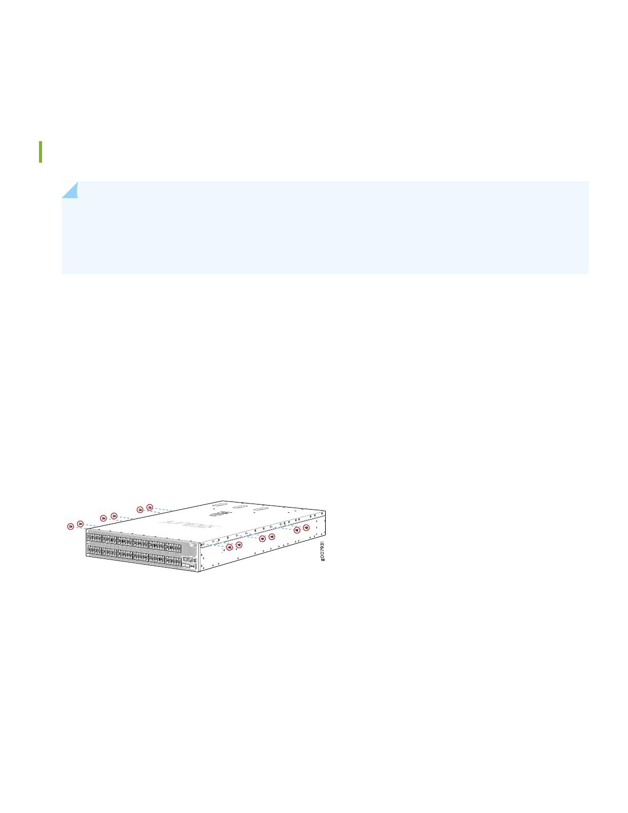
4. Using a Phillips screwdriver, remove the six screws on each side of the chassis that hold the cover to the chassis (see
the illustration below for screw locations). These screws will be replaced with the mounting screws included in the
box.
5. Align one of the front-mounting rails with the screw holes on the side of the chassis.
6. Attach the mounting rail to the PTX1000 by using 11 flat-head M4x6-mm Phillips mounting screws. Tighten the screws.
7. Repeat Step 5 and Step 6 on the opposite side of the PTX1000.
8. Either use a mechanical lift or have two people grasp both sides of the PTX1000, lift it, and position it in the rack so
that the front bracket is aligned with the rack holes.
9. Have another person secure the front of the PTX1000 to the rack by using eight mounting screws (and cage nuts and
washers if your rack requires them). Tighten the screws.
2
10. Continue to support the PTX1000 while sliding the rear-mounting blades into the channel of the side-mounting rails
and securing the blades to the rack (see the illustration below). Use eight mounting screws (and cage nuts and washers
if your rack requires them) to attach to the blade to the rack. Tighten the screws.
11. Ensure that the PTX1000 chassis is level by verifying that all the screws on the front of the rack are aligned with the
screws at the back of the rack.
12. (Optional) Attach a grounding cable to earth ground and then attach it to the chassis grounding point.
Connect Power to the PTX1000
The PTX1000 is supplied with four factory-installed power supplies. For instructions on connecting DC power, see the
installation instructions in the PTX1000 documentation.
To connect power to a PTX1000 with AC power supplies:
1. If the AC power source outlet has a power switch, set it to the OFF (0) position.
2. Insert the coupler end of the power cord into the AC power cord inlet on the AC power supply faceplate.
3. Push the power cord retainer onto the power cord.
4. Insert the power cord plug into the power source outlet.
5. If the AC power source outlet has a power switch, set it to the ON (|) position.
6. Verify that the status LED for each power supply is lit green and on steadily.
3
Step 2: Up and Running
IN THIS SECTION
Set Parameter Values | 4
Perform the Initial Configuration | 4
Set Parameter Values
You must perform the initial configuration of the PTX1000 through the console port. Before you begin, set the following
parameter values from the console server or PC:
Baud Rate—9600
Flow Control—None
Data—8
Parity—None
Stop Bits—1
DCD State—Disregard
Perform the Initial Configuration
To connect and configure the PTX1000 from the console:
1. Connect the console port to a laptop or PC using the provided RJ-45 cable and RJ-45 to DB-9 serial port adapter. The
console (CON) port is located on the port panel of the router.
2. Log in as root. There is no password. If the software booted before you connect to the console port, you might need
to press the Enter key for the prompt to appear.
login: root
3. Start the command-line interface (CLI).
root@% cli
4
4. Enter configuration mode.
root> configure
5. Add a password to the root administration user account. Enter a plain-text password
[edit]
root@# set system root-authentication plain-text-password
New password: password
Retype new password: password
6. (Optional) Configure the name of the PTX1000. If the name includes spaces, enclose the name in quotation marks (“
”).
[edit]
root@# set system host-name host-name
7. Configure the default gateway.
[edit]
root@# set routing-options static route default next-hop address
8. Configure the IP address and prefix length for the router management interface.
[edit]
root@# set interfaces em0 unit 0 family inet address address/prefix-length
NOTE: The RJ-45 management port, em0, and SFP management port, em1, are found on the management
panel of the PTX1000. They are both labeled MGMT.
9. (Optional) Configure the static routes to remote prefixes with access to the management port.
[edit]
root@# set routing-options static route remote-prefix next-hop destination-IP retain no-readvertise
10. Enable Telnet service.
[edit]
root@# set system services telnet
5
11. Enable SSH service.
[edit]
root@# commit
Step 3: Keep Going
IN THIS SECTION
Safety Warnings Summary | 6
Power Cable Warning (Japanese) | 7
Contacting Juniper Networks | 7
See the complete PTX1000 documentation at https://www.juniper.net/documentation/product/en_US/ptx1000.
Safety Warnings Summary
This is a summary of safety warnings. For a complete list of warnings, including translations, see the PTX1000 documentation
at https://www.juniper.net/documentation/product/en_US/ptx1000.
WARNING: Failure to observe these safety warnings can result in personal injury or death.
Permit only trained and qualified personnel to install or replace PTX1000 components.
Perform only the procedures described in this quick start and the PTX1000 documentation. Other services must be
performed only by authorized service personnel.
Before installing the PTX1000, read the planning instructions in the PTX1000 documentation to make sure that the site
meets power, environmental, and clearance requirements for the router.
Before connecting the router to a power source, read the installation instructions in the PTX1000 documentation.
The PTX1000 weighs 68.6 lb (31.1 kg). Installing the router in a rack or cabinet requires either a mechanical lift or two
people to lift the device and another person to secure it to the rack. To prevent injury, keep your back straight and lift
with your legs, not your back.
6
If the rack or cabinet has stabilizing devices, install them in the rack before mounting or servicing the PTX1000 in the
rack or cabinet.
Before installing or after removing an electrical component, always place it component-side up on a flat antistatic mat
or in an antistatic bag.
Do not work on the PTX1000 or connect or disconnect cables during electrical storms.
Before working on equipment that is connected to power lines, remove jewelry, including rings, necklaces, and watches.
Metal objects heat up when connected to power and ground and can cause serious burns or become welded to the
terminals.
Power Cable Warning (Japanese)
The attached power cable is only for this product. Do not use this cable for another product.
g040300
Contacting Juniper Networks
For technical support, see:
http://www.juniper.net/support/requesting-support.html
Juniper Networks, the Juniper Networks logo, Juniper, and Junos are registered trademarks of Juniper Networks, Inc. in the
United States and other countries. All other trademarks, service marks, registered marks, or registered service marks are the
property of their respective owners. Juniper Networks assumes no responsibility for any inaccuracies in this document. Juniper
Networks reserves the right to change, modify, transfer, or otherwise revise this publication without notice. Copyright © 2020
Juniper Networks, Inc. All rights reserved. Rev. 01, June 2020.
7
  • Page 1 1
  • Page 2 2
  • Page 3 3
  • Page 4 4
  • Page 5 5
  • Page 6 6
  • Page 7 7

Juniper PTX1000 Quick start guide

Type
Quick start guide

Juniper PTX1000 is a high-performance routing platform designed for service provider and enterprise networks.

Ask a question and I''ll find the answer in the document

Finding information in a document is now easier with AI