
PTX10001-20C Quick Start
PTX10001-20C Quick Start
See the complete PTX Series documentation at http://www.juniper.net/techpubs/. To install and configure a Juniper Networks
PTX10001 Router, you need:
•
Electrostatic discharge (ESD) grounding strap (not provided)
•
One pair of front mounting rails (provided)
•
One pair of rear mounting blades (provided)
•
Sixteen screws to secure the mounting rails and mounting blades to the chassis (provided)
•
Eight screws to secure the chassis and mounting blades to the rack (not provided)
•
Screwdriver appropriate for your rack mounting screws (not provided)
•
Two power cords with plugs appropriate for your geographical location (provided)
•
RJ-45 cable and RJ-45 to DB-9 serial port adapter (provided)
•
Management host, such as a PC laptop, with a serial port (not provided)
•
(Optional) Grounding cable kit with bracket, lug, and three screws. To install the grounding cable, see the PTX10001
documentation at https://www.juniper.net/documentation/product/en_US/ptx10001
Part 1: Mount the Device
The PTX10001 can be mounted in a 19-inch four-post rack.
To mount the device in a standard 19-inch rack:
1. Attach the ESD grounding strap to your bare wrist and to a site ESD point.
NOTE: If you are mounting multiple units in the rack, mount the heaviest unit at the bottom and mount the others
from bottom to top in order of decreasing weight. The PTX10001-20C weighs approximately 26.8 lbs (12.2 kg).
Installing the router in a rack requires two people to lift the device and secure it to the rack.
2. Place the rack in its permanent location, allowing adequate clearance for airflow and maintenance, and secure it to the building
structure.
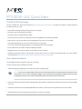
3. Determine whether the end with field replaceable units (FRUs) or the ports are to be placed at the front of the rack.
4. Align the holes in the mounting-rail with the holes on the side of the chassis.

5. Attach the mounting-rail to the router using eight mounting screws.
0
1
2
3
4
5
6
7
8
9
10
11
12
13
14
15
16
17
18
19
ALM
ID
CON
MGMT
SYS
0
1
2
3
4
5
6
7
8
9
10
11
12
13
14
15
16
17
18
19
ALM
ID
CON
MGMT
SYS
g050881
6. Repeat Step 4 and Step 5 on the opposite side of the router.
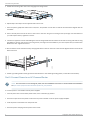
7. Have one person grasp both sides of the router, lift it, and position it in the rack so that the front bracket is aligned with the
rack holes.
8. Have a second person secure the front of the router to the rack using four mounting screws (and cage nuts and washers if
your rack requires them.) Tighten the screws.
9. Continue to support the router while sliding the rear mounting-blades into the channel of the side mounting-rails and securing
the blades to the rack. Use the four mounting screws (and cage nuts and washers if your rack requires them) to attach each
blade to the rack. Tighten the screws.
10. Ensure that the router chassis is level by verifying that all the screws on the front of the rack are aligned with the screws at the
back of the rack.
0
1
2
3
4
5
6
7
8
9
10
11
12
13
14
15
16
17
18
19
ALM
ID
CON
MGMT
SYS
g050883
11. Attach a grounding cable to earth ground and then attach it to the chassis grounding points (on the side of the chassis).
Part 2: Connect Power to an AC-Powered Router
NOTE: For instructions on connecting DC power, see the installation instructions in the PTX10001 documentation
at https://www.juniper.net/documentation/product/en_US/ptx10001.
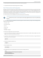
To connect power to a PTX10001 with AC power supplies:
1. If the AC power source outlet has a power switch, set it to the OFF (0) position.
2. Insert the coupler end of the power cord into the AC power cord inlet on the AC power supply faceplate.
3. Push the power cord retainer onto the power cord.
4. Insert the power cord plug into the power source outlet.
Copyright © 2018, Juniper Networks, Inc.2
PTX10001-20C Quick Start

5. If the AC power source outlet has a power switch, set it to the ON (|) position.
6. Verify that the AC and the DC LEDs are lit green and on steadily.
Part 3: Perform the Initial Configuration
By default, Zero touch provisioning (ZTP) starts automatically. Zero touch provisioning (ZTP) allows you to provision new Juniper
Networks devices in your network automatically, with minimal manual intervention. You can use either management ports or
network ports on your switch to connect to the network. When you physically connect a device to the network and boot it with
a default factory configuration, the device upgrades (or downgrades) the Junos OS release and autoinstalls a configuration file
from the network. For more information on ZTP, see Zero Touch Provisioning.
If you do not use ZTP, you must disable the ZTP process and then perform the following:
NOTE: To disable the ZTP process, manually delete the auto-image-upgrade statement located in the [edit chassis]
hierarchy.
You must perform the initial configuration of the router through the console port. Before you begin, set the following parameter
values in the console server or PC:
•
Baud Rate—9600
•
Flow Control—None
•
Data—8
•
Parity—None
•
Stop Bits—1
•
DCD State—Disregard
To connect and configure the router from the console:
1. Connect the console port to a laptop or PC using the provided RJ-45 cable and RJ-45 to DB-9 serial port adapter. The console
(CON) port is located on the port panel of the router.
2. Log in as root. There is no password. If the software booted before you connected to the console port, you might need to press
the Enter key for the prompt to appear.
login: root
3. Start the command-line interface (CLI).
root@% cli
4. Enter configuration mode.
root>configure
5. Add a password to the root administration user account. Enter a cleartext password
[edit]
root@# set system root-authentication plain-text-password
New password: password
Retype new password: password
3Copyright © 2018, Juniper Networks, Inc.
PTX10001-20C Quick Start

6. (Optional) Configure the name of the router. If the name includes spaces, enclose the name in quotation marks (“ ”).
[edit]
root@# set system host-name host-name
7. Configure the default gateway.
[edit]
root@# set routing-options static route default next-hop address
8. Configure the IP address and prefix length for the router management interface.
[edit]
root@# set interfaces em0 unit 0 family inet address address/prefix-length
NOTE: The management port em0 is on the port panel and the management port em2 is on the FRU end of the
PTX10001 router.
9. (Optional) Configure the static routes to remote prefixes with access to the management port.
[edit]
root@# set routing-options static route remote-prefix next-hop destination-IP retain no-readvertise
10. Enable telnet service.
[edit]
root@# set system services telnet
11. Enable SSH service.
[edit]
root@# set system services SSH
12. Commit the configuration to activate it on the router.
[edit]
root@# commit
Safety Warnings Summary
This is a summary of safety warnings. For a complete list of warnings, including translations, see the PTX10001 router documentation
at https://www.juniper.net/documentation/product/en_US/ptx10001.
WARNING: Failure to observe these safety warnings can result in personal injury or death.
•
Permit only trained and qualified personnel to install or replace router components.
•
Perform only the procedures described in this quick start and the PTX10001 documentation. Other services must be performed
only by authorized service personnel.
•
Before installing the router, read the planning instructions in the PTX10001 documentation to make sure that the site meets
power, environmental, and clearance requirements for the router.
Copyright © 2018, Juniper Networks, Inc.4
PTX10001-20C Quick Start

•
Before connecting the router to a power source, read the installation instructions in the PTX10001 documentation.
•
The PTX10001-20C router weighs approximately 26.8 lbs (12.2 kg). Manually installing the PTX10001-20C router in a rack
requires two people to lift the router and install the mounting screws. To prevent injury, keep your back straight and lift with
your legs, not your back.
•
If the rack has stabilizing devices, install them in the rack before mounting or servicing the router in the rack.
•
Before installing or after removing an electrical component, always place it component-side up on a flat antistatic mat or in
an antistatic bag.
•
Do not work on the router or connect or disconnect cables during electrical storms.
•
Before working on equipment that is connected to power lines, remove jewelry, including rings, necklaces, and watches. Metal
objects heat up when connected to power and ground and can cause serious burns or become welded to the terminals.
Power Cable Warning (Japanese)
The attached power cable is only for this product. Do not use this cable for another product.
g040300
Contacting Juniper Networks
For technical support, see:
http://www.juniper.net/support/requesting-support.html
Juniper Networks, the Juniper Networks logo, Juniper, and Junos are registered trademarks of Juniper Networks, Inc. and/or its affiliates in the United States
and other countries. All other trademarks may be property of their respective owners. Juniper Networks assumes no responsibility for any inaccuracies in this
document. Juniper Networks reserves the right to change, modify, transfer, or otherwise revise this publication without notice. Copyright © 2018 Juniper
Networks, Inc. All rights reserved. Rev. 01, October 2018.
PTX10001-20C Quick Start
-
 1
1
-
 2
2
-
 3
3
-
 4
4
-
 5
5


Ask a question and I''ll find the answer in the document
Finding information in a document is now easier with AI
Related papers
-
Juniper JRR200 Quick start guide
-
-
-
-
-
-
-
-
Juniper ACX Series Quick start guide
-
