Quick Start Guide
Class 1 laser CMOS analog sensor with an analog output. Patent pending.
This guide is designed to help you set up and install the Q4X Analog Sensor
. For complete information on programming,
performance, troubleshooting, dimensions, and accessories, please refer to the Instruction Manual at
www.bannerengineering.com. Search for p/n 185624 to view the Instruction Manual. Use of this document assumes
familiarity with pertinent industry standards and practices.
For illustration purposes, the threaded barrel model Q4X images are used throughout this document.
WARNING: Not To Be Used for Personnel Protection
Never use this device as a sensing device for personnel protection. Doing so could lead to
serious injury or death. This device does not include the self-checking redundant circuitry necessary
to allow its use in personnel safety applications. A sensor failure or malfunction can cause either an
energized or de-energized sensor output condition.
Features
1
2
3
Figure 1. Sensor Features—Threaded Barrel
Models
1. Output Indicator (Amber)
2.
Display
3.
Buttons
1
2
3
Figure 2. Sensor Features—Flush Mount
Models
Display and Indicators
The display is a 4-digit, 7-segment LED. The main screen is the Run Mode screen, which shows the current distance to the
target in millimeters.
Figure 3. Display in Run Mode
1. Stability Indicator (STB = Green)
2. Active TEACH Indicators
2-PT = Two-Point TEACH (Amber)
1-PT = One-Point TEACH (Amber)
3. Display Value Indicator (MM = Amber)
Output Indicator
On—Displayed distance is within the taught analog
output window
Off—Displayed distance is outside of the taught
analog output window
Stability Indicator (STB)
On—Stable signal within the specified sensing range
Flashing—Marginal signal, the target is outside of
the limits of the specified sensing range, or a
multiple peak condition exists
Off—No target detected within the specified sensing
range
Active TEACH Indicators (2PT and 1PT)
2-PT on—Two-point TEACH mode selected (default)
1-PT on—One-point TEACH mode selected
Display Value Indicator (MM)
On—Display shows the distance in millimeters
(default)
Off—Display shows the analog output value
Q4X Stainless Steel Analog Laser Sensor
Original Document
185623 Rev. D
7 September 2016
185623
Buttons
Use the sensor buttons (SELECT)(TEACH), (+)(DISP), and (-)(MODE) to program the sensor.
(SELECT)(TEACH)
Press and hold for longer than 2 seconds to start
the currently selected TEACH mode (the default is
two-point TEACH)
Press to select menu items in Setup mode
(-)(MODE)
Press to change the distance setting for the 0 V (4
mA ) point; press and hold to decrease numeric
values
Press and hold for longer than 2 seconds to enter
Setup mode
Press to navigate the sensor menu in Setup mode
(+)(DISP)
Press to change the distance setting for the 10 V
(20 mA) point; press and hold to increase numeric
values
Press and hold for longer than 2 seconds to toggle
the display value between the distance and the
analog output
Press to navigate the sensor menu in Setup mode
NOTE: When navigating the menu, the
menu items loop.
Laser Description and Safety Information
CAUTION: Use of controls or adjustments or performance of procedures other than those specified
herein may result in hazardous radiation exposure. Do not attempt to disassemble this sensor for
repair. A defective unit must be returned to the manufacturer.
Class 1 Lasers
Class 1 lasers are lasers that are safe under reasonably foreseeable conditions of operation, including the use of optical
instruments for intrabeam viewing.
Laser wavelength: 655 nm Output: < 0.20 mW Pulse Duration:
7 µs to 2 ms
Installation
Install the Safety Label
The safety label must be installed on Q4X sensors that are used in the
United States.
NOTE: Position the label on the cable in a location that
has minimal chemical exposure.
1. Remove the protective cover from the adhesive on the label.
2. Wrap the label around the
Q4X cable, as shown.
3. Press the two halves of the label together.
COMPLIES WITH IEC 60825-1:2007
CLASS 1
LASER PRODUCT
COMPLIES WITH 21 CFR 1040.10 AND 1040.11
EXCEPT
FOR DEVIATIONS PURSUANT TO
LASER NOTICE No. 50, DATED JUNE 24, 2007.
BANNER ENGINEERING CORP.
9714 10TH A
VENUE NORTH
MINNEAPOLIS, MN 55441
COMPLIES WITH IEC 60825-1:2007
CLASS 1
LASER PRODUCT
Figure 4. Safety Label Installation
Q4X Stainless Steel Analog Laser Sensor
2 www.bannerengineering.com - Tel: +1-763-544-3164 P/N 185623 Rev. D
Sensor Orientation
Optimize detection reliability and performance with correct sensor-to-target orientation. To ensure reliable detection,
orient the sensor as shown in relation to the target to be detected.
Figure 5. Optimal Orientation of Target to Sensor
See the following figures for examples of correct and incorrect sensor-to-target orientation as certain placements may
pose problems for sensing some targets.
Incorrect
Correct
Figure 6. Orientation by a wall
Incorrect
Correct
Figure 7. Orientation for a turning object
Incorrect
Correct
Figure 8. Orientation for a height difference
Horizontal
Orientation
Vertical
Orientation
(Optimal)
Figure 9. Orientation for a color or luster difference
Mount the Sensor
1.
If a bracket is needed, mount the sensor onto the bracket.
2.
Mount the sensor (or the sensor and the bracket) to the machine or equipment at the desired location. Do not tighten
the mounting screws at this time.
3. Check the sensor alignment.
4. Tighten the mounting screws to secure the sensor (or the sensor and the bracket) in the aligned position.
Wiring Diagram
3
1
2
4
5
12-30V dc
Remote
Teach
Shield
Load
+
Analog Out
Analog Gnd
NOTE: Open lead wires must be connected to a terminal block.
1
4
5
3
2
Key
1 = Brown
2 = White
3 = Blue
4 = Black
5 = Gray
Q4X Stainless Steel Analog Laser Sensor
P/N 185623 Rev. D www.bannerengineering.com - Tel: +1-763-544-3164 3
NOTE: The input wire function is user-selectable; see the Instruction Manual for details
. The default
for the input wire function is off (disabled).
NOTE: Shielded cordsets are recommended for all models with quick disconnect fittings. It is
recommended that the shield wire be connected to -V dc (the blue wire).
Cleaning and Maintenance
Handle the sensor with care during installation and operation. Sensor windows soiled by fingerprints, dust, water, oil, etc.
may create stray light that may degrade the peak performance of the sensor. Blow the window clear using filtered,
compressed air, then clean as necessary using water and a lint-free cloth.
Sensor Programming
Program the sensor using the buttons on the sensor or the remote input (limited programming options).
In addition to programming the sensor, use the remote input to disable the buttons for security, preventing unauthorized
or accidental programming changes. See the Instruction Manual, p/n 185624 for more information.
Setup Mode
1. Access Setup mode and the sensor menu from Run mode by pressing and holding MODE for longer than 2
seconds.
2. Use
and to navigate through the menu.
3. Press SELECT
to select a menu option and access the submenus.
4. Use
and to navigate through the submenus.
5. Select a submenu option.
Press SELECT to select a submenu option and return to the top menu.
Press and hold SELECT for longer than 2 seconds to select a submenu option and return immediately to
Run mode.
To exit Setup mode and return to Run mode, navigate to
and press SELECT.
Q4X Stainless Steel Analog Laser Sensor
4 www.bannerengineering.com - Tel: +1-763-544-3164 P/N 185623 Rev. D
two-point teach
one-point teach
Top Menu
set Base Measurement Rate to 0.3 ms
set Base Measurement Rate to 0.5 ms
set Base Measurement Rate to 1.0 ms
set Base Measurement Rate to 5.0 ms
set Base Measurement Rate to 2.5 ms
near: set zero displayed value to end of 18 mm barrel
far: set zero displayed value to maximum detection range
laser off when pulled low
set: Remote Teach input
off: remote teach input is not active
master
laser on when pulled low
slave
trigger
display on
display on, inverted
display off (enters sleep mode after 60 seconds)
display off, inverted (enters sleep mode after 60 seconds)
end: select to exit setup
no: do not reset to factory defaults
yes: reset to factory defaults
on: move the zero point after each teach
hold
off: zero point is either at end of barrel or
maximum
detection range
Teach Process Selection
Base Measurement Rate
Select Zero Reference Location
Shift Zero Reference after Teach
Input Wire Function
Display Read
Exit Setup
Reset to Factory Defaults
Sub Menus
( default setting)
Trigger Mode appears when Input Wire Function is set to “trigger”
positive slope
negative slope
Slope
average 1 measurement for analog output
average 2 measurements for analog output
average 4 measurements for analog output
average 8 measurements for analog output
average 16 measurements for analog output
average 32 measurements for analog output
average 64 measurements for analog output
average 128 measurements for analog output
average 256 measurements for analog output
average 512 measurements for analog output
Averaging
(3.5 mA)
(20.5 mA)
Loss of Signal
max. distance
range (max. dist - min. dist)
average measurement
track max. distance
min. distance
track min. distance
sample measurement
Trigger Mode
hold
(0 V)
(10.5 V)
voltage modelscurrent models
Figure 10. Sensor Menu Map
Q4X Stainless Steel Analog Laser Sensor
P/N 185623 Rev. D www.bannerengineering.com - Tel: +1-763-544-3164 5
Basic TEACH Instructions
Use the following instructions to teach the Q4X sensor. The instructions provided on the sensor display vary depending on
the type of TEACH mode selected. Two-point TEACH is the default TEACH mode.
1.
Press and hold TEACH for longer than 2 seconds to start the selected TEACH mode.
2. Present the target.
3. Press TEACH to teach the target. The target is taught and the sensor waits for the second target, if required by the
selected TEACH mode, or returns to Run mode.
Complete steps 4 and 5 only if required for the selected TEACH mode:
4. Present the second target.
5. Press TEACH to teach the target. The target is taught and the sensor returns to Run mode.
Manual Adjustments
Manually adjust the distance set for the 0 V (4 mA) and 10 V (20 mA) values using the
and buttons. The available
adjustments vary depending on the TEACH mode selected.
Locking and Unlocking the Sensor Buttons
Use the lock and unlock feature to prevent unauthorized or accidental programming changes. Three settings are available:
—The sensor is unlocked and all settings can be modified (default).
— The sensor is locked and no changes can be made.
—The value associated with 0 V (4 mA) and 10 V (20 mA ) can be changed by teaching or manual
adjustment, but no sensor settings can be changed through the menu.
When in mode, displays when the (SELECT)(TEACH) button is pressed. The analog point displays when
(+)
(DISP) or (-)(MODE) are pressed, but
displays if the buttons are pressed and held.
When in
mode, displays when (+)(DISP) or (-)(MODE) are pressed and held. To access the manual
adjust options, briefly press and release (+)
(DISP) or (-)(MODE). To enter TEACH mode, press the (SELECT)(TEACH)
button and hold for longer than 2 seconds.
To enter
mode, hold and press four times. To enter mode, hold and press seven times.
Holding and pressing four times unlocks the sensor from either lock mode and the sensor displays .
Q4X Stainless Steel Analog Laser Sensor
6 www.bannerengineering.com - Tel: +1-763-544-3164 P/N 185623 Rev. D
Specifications
Sensing Beam
Visible red Class 1 laser, 655 nm
Supply Voltage (Vcc)
12 to 30 V dc
Power and Current Consumption, exclusive of load
< 675 mW
Sensing Range—Threaded Barrel Models
300 mm models: 25 mm to 300 mm (0.98 in to 11.81 in)
100 mm models: 25 mm (0.98 in) to 100 mm (3.94 in)
Sensing Range—Flush Mount Models
310 mm models: 35 mm to 310 mm (1.38 in to 12.20 in)
110 mm models: 35 mm to 110 mm (1.38 in to 4.33 in)
Analog Output Configuration
0 to 10 V or 4 to 20 mA, depending on model
Output Rating
Analog Voltage Outputs (Q4X..U Models): 2.5 kOhm minimum load
resistance
Analog Current Outputs (Q4X..I Models): 1 kΩ maximum load
resistence at 24 V; maximum load resistance = [(Vcc – 4.5)/0.02 Ω]
Remote Input
Allowable Input Voltage Range: 0 to Vcc
Active Low (internal weak pullup—sinking current): Low State < 2.0
V at 1 mA max.
Supply Protection Circuitry
Protected against reverse polarity and transient overvoltages
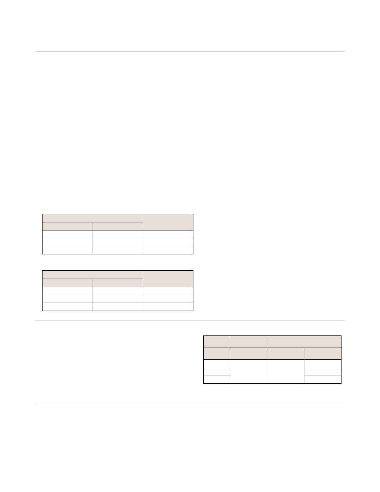
Beam Spot Size
Table 1: Beam Spot Size—Long-Range Models
Distance (mm) Size (Horizontal ×
Vertical)
Threaded Barrel Models Flush Mount Models
25 35 2.6 mm × 1.0 mm
150 160 2.3 mm × 0.9 mm
300 310 2.0 mm × 0.8 mm
Table 2: Beam Spot Size—Short-Range Models
Distance (mm) Size (Horizontal ×
Vertical)
Threaded Barrel Models Flush Mount Models
25 35 2.4 mm × 1.0 mm
50 60 2.2 mm × 0.9 mm
100 110 1.8 mm × 0.7 mm
Analog Resolution—Threaded Barrel Models
300 mm models:
25 mm to 100 mm: < 0.3 mm
100 mm to 300 mm: < 1 mm
100 mm models: 25 mm to 100 mm: < 0.15 mm
Analog Resolution—Flush Mount Models
310 mm models:
35 mm to 110 mm: < 0.3 mm
110 mm to 310 mm: < 1 mm
110 mm models:
35 mm to 110 mm: < 0.15 mm
Analog Linearity
Analog linearity performance matches accuracy performance curve
(see Performance Curves—Threaded Barrel Models on page 8
and Performance Curves—Flush Mount Models on page 9).
Response Speed
Total response speed varies from 0.5 ms to 2560 ms, depending on
base measurement rate and averaging settings.
See Instruction Manual for more information.
Delay at Power Up
< 750 ms
Ambient Light Immunity
> 5,000 lux
Maximum Torque
Side mounting: 1 N·m (9 in·lbs)
Nose mounting: 20 N·m (177 in·lbs)
Connector
Integral 5-pin M12/Euro-style male quick disconnect (QD)
Construction
Housing: 316 L stainless steel
Lens cover: PMMA acrylic
Lightpipe and display window: polysulfone
Chemical Compatibility
Compatible with commonly used acidic or caustic cleaning and
disinfecting chemicals used in equipment cleaning and sanitation.
ECOLAB
®
certified.
Compatible with typical cutting fluids and lubricating fluids used in
machining centers
Application Note
For optimum performance, allow 10 minutes for the sensor to warm
up
Environmental Rating
IEC IP67
per IEC60529
IEC IP68
per IEC60529
IEC IP69K per DIN40050-9
Shock
MIL-STD-202G, Method 213B, Condition I (100G 6x along X, Y and Z axes,
18 total shocks), with sensor operating
Vibration
MIL-STD-202G, Method 201A (10 Hz to 60 Hz, 0.06 inch (1.52 mm)
double amplitude, 2 hours each along X, Y and Z axes), with sensor
operating
Storage Temperature
–25 °C to +75 °C (13 °F to +167 °F)
Operating Conditions
35% to 95% relative humidity
Min. Ambient
Temp (°C)
Max. Ambient Temp (°C)
Vcc All Models
Q4X…U
(0–10V)
Q4X..I
(4–20 mA)*
12
–10 50
50
24 45
30 40
* For 4–20 mA models only: Max. Ambient Sensor Temp (°C) = 50
– (Vcc – 12)/2
Q4X Stainless Steel Analog Laser Sensor
P/N 185623 Rev. D www.bannerengineering.com - Tel: +1-763-544-3164 7
Required Overcurrent Protection
WARNING: Electrical connections must be
made by qualified personnel in accordance with
local and national electrical codes and
regulations.
Overcurrent protection is required to be provided by end product
application per the supplied table.
Overcurrent protection may be provided with external fusing or via Current
Limiting, Class 2 Power Supply.
Supply wiring leads < 24 AWG shall not be spliced.
For additional product support, go to http://www.bannerengineering.com.
Supply Wiring (AWG) Required Overcurrent Protection (Amps)
20 5.0
22 3.0
24 2.0
26 1.0
28 0.8
30 0.5
Certifications
Industrial
Control
Equipment
3TJJ
Class 2 power
UL Environmental Rating: Type 1
chemical compatibility certified
ECOLAB is a registered trademark of Ecolab USA Inc. All rights
reserved.
Performance Curves—Threaded Barrel Models
Accuracy (90% to 6% reflectance)
DISTANCE (mm)
Accuracy ( ± mm)
0
0
0.25
0.50
0.75
1.00
1.25
50 100
25 75
Figure 11. 100 mm Models
0
1
2
3
4
5
6
7
9
8
10
500 100 150 200 250 300
DISTANCE (mm)
Accuracy ( ± mm)
Figure 12. 300 mm Models
Repeatability (90% to 6% reflectance)
DISTANCE (mm)
Repeatability ( ± mm)
0
0
0.05
0.075
0.10
0.15
0.20
0.25
0.30
0.35
50 100
Averaging = 1
Averaging = 512
25
Figure 13. 100 mm Models
0
0.5
1.0
1.5
2.0
2.5
3.0
3.5
500 100 150 200 250 300
DISTANCE (mm)
Averaging = 1
Averaging = 512
Repeatability ( ± mm)
Figure 14. 300 mm Models
Q4X Stainless Steel Analog Laser Sensor
8 www.bannerengineering.com - Tel: +1-763-544-3164 P/N 185623 Rev. D
Temperature Effects
0
0.05
0.10
0.15
0.20
0.25
0.30
0.35
500 100 150 200 250 300
DISTANCE (mm)
Temperature Effect (± mm / °C)
Performance Curves—Flush Mount Models
Accuracy (90% to 6% reflectance)
DISTANCE (mm)
Accuracy ( ± mm)
0
0
0.25
0.50
0.75
1.00
1.25
50 100
110
35
Figure 15. 110 mm Models
0
1
2
3
4
5
6
7
9
8
10
500 100 150 200 250 300
DISTANCE (mm)
Accuracy ( ± mm)
310
35
Figure 16. 310 mm Models
Repeatability (90% to 6% reflectance)
DISTANCE (mm)
Repeatability ( ± mm)
0
0
0.05
0.075
0.10
0.15
0.20
0.25
0.30
0.35
50 100
35
110
Averaging = 1
Averaging = 512
Figure 17. 110 mm Models
0
0.5
1.0
1.5
2.0
2.5
3.0
3.5
500 100 150 200 250 300
DISTANCE (mm)
Filter = 1
Filter = 512
Repeatability ( ± mm)
35
310
Figure 18. 310 mm Models
Q4X Stainless Steel Analog Laser Sensor
P/N 185623 Rev. D www.bannerengineering.com - Tel: +1-763-544-3164 9
Temperature Effects
0
0.05
0.10
0.15
0.20
0.25
0.30
0.35
500 100 150 200 250 300
DISTANCE (mm)
Temperature Effect (± mm / °C)
310
35
Banner Engineering Corp. Limited Warranty
Banner Engineering Corp. warrants its products to be free from defects in material and workmanship for one year following the date of shipment. Banner Engineering Corp.
will repair or replace, free of charge, any product of its manufacture which, at the time it is returned to the factory, is found to have been defective during the warranty
period. This warranty does not cover damage or liability for misuse, abuse, or the improper application or installation of the Banner product.
THIS LIMITED WARRANTY IS EXCLUSIVE AND IN LIEU OF ALL OTHER WARRANTIES WHETHER EXPRESS OR IMPLIED (INCLUDING, WITHOUT LIMITATION,
ANY WARRANTY OF MERCHANTABILITY OR FITNESS FOR A PARTICULAR PURPOSE), AND WHETHER ARISING UNDER COURSE OF PERFORMANCE, COURSE
OF DEALING OR TRADE USAGE.
This Warranty is exclusive and limited to repair or, at the discretion of Banner Engineering Corp., replacement. IN NO EVENT SHALL BANNER ENGINEERING CORP. BE
LIABLE TO BUYER OR ANY OTHER PERSON OR ENTITY FOR ANY EXTRA COSTS, EXPENSES, LOSSES, LOSS OF PROFITS, OR ANY INCIDENTAL,
CONSEQUENTIAL OR SPECIAL DAMAGES RESULTING FROM ANY PRODUCT DEFECT OR FROM THE USE OR INABILITY TO USE THE PRODUCT, WHETHER
ARISING IN CONTRACT OR WARRANTY, STATUTE, TORT, STRICT LIABILITY, NEGLIGENCE, OR OTHERWISE.
Banner Engineering Corp. reserves the right to change, modify or improve the design of the product without assuming any obligations or liabilities relating to any product
previously manufactured by Banner Engineering Corp. Any misuse, abuse, or improper application or installation of this product or use of the product for personal protection
applications when the product is identified as not intended for such purposes will void the product warranty. Any modifications to this product without prior express approval
by Banner Engineering Corp will void the product warranties. All specifications published in this document are subject to change; Banner reserves the right to modify product
specifications or update documentation at any time. Specifications and product information in English supersede that which is provided in any other language. For the most
recent version of any documentation, refer to: www.bannerengineering.com.
Q4X Stainless Steel Analog Laser Sensor
©
Banner Engineering Corp. All rights reserved
  • Page 1 1
  • Page 2 2
  • Page 3 3
  • Page 4 4
  • Page 5 5
  • Page 6 6
  • Page 7 7
  • Page 8 8
  • Page 9 9
  • Page 10 10

Ask a question and I''ll find the answer in the document

Finding information in a document is now easier with AI