Guest 4006, 4008, 4012 and 4018 DYNAPLATES User manual
- Type
- User manual

DYNAPLATES
INSTALLATION INSTRUCTIONS
(ITEM #’S: 4006, 4008, 4012 & 4018)
Description
The Guest Dynaplate is made from thousands of tiny bronze spheres bonded together
by heat and pressure into a porous plate. This porosity makes the Dynaplate ideal
for use in electrical bonding systems. It can also be used in RF applications such
as grounding SSB and LORAN antennas for improved performance. NOTE: Minor
discoloration does not eect performance.
Installing the Dynaplate
Required tools and materials:
• Electric drill with drill bit (see table below)
• Wrench (see table below)
• Large slot-head screwdriver
• Caulking suitable for underwater use (StarBrite™83301 or similar)
Dynaplate
Item # Wrench
required Drill bit
required
4006, 4008 7/16" 1/4" (6mm)
4012, 4018 9/16" 3/8" (9mm)
Downloaded from Arrow.com.

marinco.com | 800.307.6702
2
INSTALLATION INSTRUCTIONS: DYNAPLATES
Step 1: Choosing a mounting location
Choose a mounting location that will always be submerged, even when the vessel is
planing or heeling over.
• On a powerboat, the best location is usually any at area on the aft third of the
bottom of the hull within a few feet of the vessel's centerline. (Avoid mounting the
Dynaplate on the vessel's transom. When underway, it may only have intermittent
contact with the water.)
• On a sailboat, a at location on the aft half of the hull and close to the centerline is
best.
Avoid mounting your Dynaplate immediately forward of any depth nder or knot
meter transducers. The gentle turbulence directly aft of the Dynaplate may aect the
performance of some devices. Propellers are not aected.
Consider the thickness of the hull when choosing a mounting location. The combined
thickness of the hull and a backing plate (not included) should not exceed 1½" (3.8 cm)
to allow use of the supplied 3" (7.6 cm) fasteners.
When choosing a mounting location, be sure you will have access to the inside of the
hull in that area to tighten fasteners and make wiring connections. Avoid areas where
drilling may damage fuel or water tanks, plumbing, or wiring.
Step 2: Preparing the mounting location
After you have selected a location for your Dynaplate:
1) Prepare a backing plate to mount inside the hull behind the Dynaplate. This plate
should be no smaller than the Dynaplate, and a minimum of 1/2" (12mm) thick.
The backing plate can be made from marine-grade plywood, a hardwood such as
mahogany or oak, or berglass.
2) Use the Dynaplate as a template to mark the locations of its mounting holes onto
the backing plate. Use the table shown under "Required tools and materials" to
determine which size drill bit you will need, then drill the holes in the backing plate
at the marked locations.
3) Hold the Dynaplate against the outside of the hull where you plan to mount it.
Align the Dynaplate parallel with the centerline of your vessel, with its sloped ends
pointing fore and aft.
4) Observe the gap between the Dynaplate and hull. If any edge of the Dynaplate
is more than 1/4" (6 mm) from the surface of the hull, select a atter mounting
location.
5) If the mounting location is suitable, use a pencil to mark the centers of the holes in
the Dynaplate onto the hull.
6) Drill one hole at one marked location on the hull. Before drilling any other holes,
examine the inside of the hull to conrm that the mounting location is suitable.
Then drill the other hole(s) through the hull at the marked location(s).
Downloaded from Arrow.com.Downloaded from Arrow.com.

marinco.com | 800.307.6702 3
INSTALLATION INSTRUCTIONS: DYNAPLATES
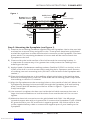
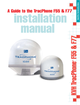
Step 3: Mounting the Dynaplate (see Figure 1)
7) Examine the mounting hardware supplied with the Dynaplate. Notice that one bolt
and two hex nuts are shiny and gold in color. These pieces have been gold plated
and will be used later to make the electrical connection to the Dynaplate. Put these
pieces aside. The remaining hardware is bronze and will be used to attach the
Dynaplate to the hull.
8) Clean and dry the inside surface of the hull around the mounting location. It
is important to remove any oil or grease that could prevent the caulking from
adhering to the hull.
9) Apply a bead of underwater caulking sealant, (StarBrite™ 83301 or similar), to the
inside of the hull in a circle around each mounting hole. Squeeze a small amount
of caulking into each mounting hole. (DO NOT coat the back of the Dynaplate with
sealant.)
10) Place the backing plate on to the caulking, aligning the holes in the backing plate
with the mounting holes in the hull. Press down on the backing plate rmly. Allow
the caulking to cure for 15 minutes.
11) Align the Dynaplate over the mounting holes on the outside of the hull. Mount the
Dynaplate by passing the bronze bolt(s) through the Dynaplate, hull and backing
plate. Fasten with at washer(s) and nut as shown in gure 1. Tighten the hex
nut(s) hand-tight.
12) Use a wrench to tighten the hex nuts inside the hull while someone else uses a
large slot head screwdriver to hold the bolts from outside the hull. Do not over
tighten.
13) Make the electrical connections to the gold plated bolt ONLY. Use #8 gauge
stranded copper wire with a ring terminal to connect the Dynaplate to your LORAN
RF ground and/or your DC accessories' negative ground. Use a wire equal in size
to the negative battery cable to connect the negative post of your battery to the
Dynaplate.
Hull
Caulking
DYNAPLATE
Gold
plated
bolt
Bronze
plated
bolt
Bronze washer
Bronze hex nut
Gold plated
hex nuts Wire
connection(s)
Backing plate
Figure 1
Downloaded from Arrow.com.Downloaded from Arrow.com.Downloaded from Arrow.com.

MRV WIPER MOTOR
INSTALLATION INSTRUCTIONS
(ITEM #’S: 34001, 34011, 34000, 34010, 34210, 34005, 34015
38001, 38011, 38000, 38010, 38005)
INSTALLATION INSTRUCTIONS: DYNAPLATES
marinco.com | 800.307.6702 | I-22688_0415
Maintenance
Do not paint the Dynaplate. Paint will prevent proper grounding. It is dicult for
barnacles to attach themselves onto its porous surface. Clean with sti brush and
bleach. Inspect annually.
P-12D34 1/4"-20 sil. brz. bolt 4006, 4008
P-12D35 1/4"-20 sil. brz. bolt-gold plated 4006, 4008
P-13A27 1/4"-20 sil. brz. nut 4006, 4008
P-13A28 1/4"-20 sil. brz. nut-gold plated 4006, 4008
P-11D03 1/4" sil. brz. washer 4006, 4008
P-12D36 3/8"-16 sil. brz. bolt 4012, 4018
P-12D37 3/8"-16 sil. brz. bolt-gold plated 4012, 4018
P-12A29 3/8"-16 sil. brz. nut 4012, 4018
P-13A2A 3/8"-16 sil. brz. nut-gold plated 4012, 4018
P-11D04 3/8"-16 sil. brz. washer 4012, 4018
LIMITED WARRANTY
For customer convenience, Marinco warranty is located at marinco.com/limited-
warranty.
Marinco is a proven industry leader, with a Global network of sales, distribution, and
service. Product concerns as related to Form, Fit and Function may be submitted
online at marinco.com/limited-warranty.
Please ll in the online form titled Marinco RMA Request and we will contact you with
any questions or concerns.
Downloaded from Arrow.com.Downloaded from Arrow.com.Downloaded from Arrow.com.Downloaded from Arrow.com.
-
 1
1
-
 2
2
-
 3
3
-
 4
4


Guest 4006, 4008, 4012 and 4018 DYNAPLATES User manual
- Type
- User manual
Ask a question and I''ll find the answer in the document
Finding information in a document is now easier with AI
Related papers
Other documents
-
MARINCO 10106 User manual
-
Garmin GBR 21 User manual
-
Sailor 150 FleetBroadband Installation guide
-
COBHAM Sailor 150 FleetBroadband Installation guide
-
 KVH TracPhone F77 Installation guide
-
KVH Industries FB250 Installation guide
-
-
-
Raymarine SmartPilot SPX-10 Installation guide
-
COBHAM Sailor 500 FleetBroadband Installation guide
