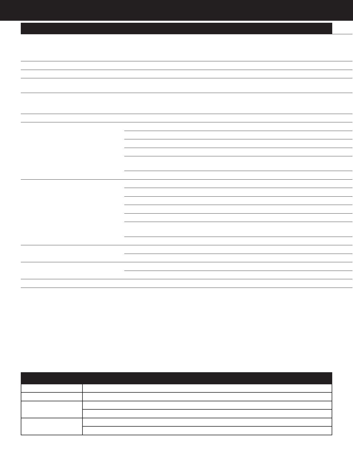
senva PW30 User manual

Type
User manual

Senva PW30 is a versatile wet-wet pressure transmitter designed for accurate and reliable pressure measurement in various industrial applications. Its key capabilities include:

  • Differential Pressure Measurement: The PW30 measures the pressure difference between two points, making it ideal for monitoring pressure drops, flow rates, and liquid levels.

  • Wide Pressure Range: With sensor options ranging from 15 PSIG to 500 PSIG, the PW30 can handle a wide variety of pressure requirements.

  • Multiple Output Options: The device offers flexible output options, including 4-20mA, 0-5V, and 0-10V, allowing for easy integration with different control systems.

INSTALLATION INSTRUCTIONS
senvainc.com 1-866-660-8864 (F)1-503-296-2529 9290 SW Nimbus Ave. Beaverton Oregon 97008
PW30
Wet-Wet Pressure Transmitter
PRODUCT APPLICATION LIMITATION:
Senva products are not designed for life or safety applications. Senva products
are not intended for use in critical applications such as nuclear facilities, human
implantable device or life support. Senva is not liable, in whole or in part, for
any claims or damages arising from such uses.
INSTALLATION
1. Identify PWC sensors A & B and their respective PSIG rating.
If the expected system gauge pressure exceeds the PSIG
rating on the PWT sensors call factory and DO NOT proceed
with install.
Max PSIG Rating
Sensor PSI Rating: PWT
Maximum PSIG Rating
025 = 25 PSIG
050 = 50 PSIG
100 = 100 PSIG
250 = 250 PSIG
500 = 500 PSIG
2. Plumb PWT sensors to media. Sensor A is intended for
supply pressure and sensor B is intended for return pressure
of the system. Plumb PWT sensors to the side or top of pipe,
as plumbing to the bottom will cause sediment to settle and
could clog or aect sensor accuracy. It is advisable to use a
single wrap of PTFE tape on the PWT sensors threads, or
other thread sealing alternative, to improve sensor accuracy.
No bypass valve manifold is necessary. Use only Senva gauge
pressure sensor elements provided with your transmitter.
Optional shuto valves are available - Senva recommends
closing service valves when ushing system to prevent
containments and water hammer from damaging PWT sensing
elements.
4. Run the appropriate length cables between the PW
transmitter and PWT sensors.
Senva recommends 22AWG stranded, 4 conductor shielded
cable to wire between the PW transmitter and PWT sensors.
5. Loosen the top screw on each PWT sensor and remove the
terminal block for wiring as shown below:
IMPORTANT WARNINGS
Only qualied trade installers should install this product
This product is not intended for life-safety applications
Do not install in hazardous or classied locations
The installer is responsible for all applicable codes
De-energize power supply prior to installation or service
IMPORTANT!
-Do NOT exceed gauge pressure rating of sensor.
-Use ONLY Senva gauge pressure sensors provided with your
PW transmitter to obtain the specied transmitter accuracy.
-Follow instructions step by step to ensure proper setup. Conduit Adapter Terminal Block Rubber Gasket PWT Element
6. Run the cable through the conduit adapter and connect the
wires to the PWT terminal block. Note that the conduit terminal
block is numbered and color coded to match the terminal label
colors on the PW transmitter.
IMPORTANT: DO NOT connect the shield at the PWT sensor
element end. The shielding should only be connected to
the ground terminal at the PW transmitter end.
TERMINAL COLOR
TERMINAL WIRING
1
2
3
TERMINAL NUMBER
Pin Connection Color
1 PWR Red
2 GND Green
3 Signal (S1/S2) White
Shield Black
7. Reassemble the PWT conduit adapter and terminal block.
Place the rubber cover back on the conduit adapter and plug
the adepter onto the PWT sensor. Tighten the assembly screw.
DO NOT attempt to plumb or tighten the PWT sensors while
wires are attached, as you run the risk of pulling wires from
cable attachments.
8. Wire PWT sensors A & B to the PW Transmitter terminals
labeled A & B respectively. See above table if wiring a pre
ordered cable length for color coordination. For strain relief,
tighten cable glands.
IMPORTANT: Shielding should be connected to the shield
( ) Terminal at the PW transmitter end, and left
unconnected at the PWT sensor element end.
9. Connect conduit ttings to the PWT sensors and PW
transmitter. Use water tight ttings if required by your
installation conditions.
10. Wire PW transmitter for voltage or current output as shown
(Remote zero wiring is optional):
11. Select 20mA, 5V or 10V output using OUTPUT switch based
on wiring conguration.
OUTPUT
4-20mA
0-5V
0-10V
12. Congure output range and sensor PSIG using DIP switches
1-7. DIP 1-3 set the sensor PSIG corresponding to the PWT
ordered. DIP 4-7 are used to set the desired output signal
range. Both use the binary code system outlined in the table.
PW Transmitter DIP Switch Conguration:
PWR
TRNT
RTN
V
ZERO
ZERO
SENSOR A SENSOR B
PWR
S1
GND
PWR
S2
GND
DIP Switch Settings
LEFT
0 (o)
0
0
0
0
0
0
KPA
BI
FAST
B-A
ABS
DIP
1
2
3
4
5
6
7
8
9
10
11
12
Function
SENSOR2
SENSOR1
SENSOR0
RANGE3
RANGE2
RANGE1
RANGE0
Units
UNI/BI
MODE
SWAP
ABS
RIGHT
1 (on)
1
1
1
1
1
1
PSI
UNI
SLOW
A-B
+/-
1-3
0000
0001
0010
0011
0100
0101
0110
0111
1000
1001
1010
1011
1100
1101
1110
1111
0-1
0-2
0-5
0-10
0-15
0-20
0-25
0-30
0-40
0-50
0-75
0-100
0-125
0-150
0-250
0-500
Binary SENSOR
(PSIG)
000
001
010
011
100
101
110
111
TEST
15*
25*
50
100
200*
250
500
4-7
DIP
Binary RANGE
(PSID)
DIP
ON
1 2 3 4 5 6 7 8 9 10 11 12
*15, 25 and 200 PSIG sensors are not oered by senva.
13. Inspect LCD for readings. LCD toggles between sensor A
reading, sensor B reading, and PSID reading.
Sensor A reading is indicated by a tick mark on the top left of
LCD. Sensor B reading is indicated by a tick mark at the bottom
left of LCD. PSID reading is displayed without any mark at the
left of the LCD.
O/R symbol will ash in bottom center of LCD if dierential
pressure reading is over range. If this occurs, select larger PSID
range to avoid clipping of readings.
14. Check remaining DIP switch (8-12) congurations for
additional setup options:
Units: LCD will display readings in PSI or kPa. LCD will indicate
PSI or kPa at top of screen.
UNI/BI: PW transmitter can be setup in Uni or Bi directional
mode.
Bi-Directional Mode Example range set at 100 PSID:
A B DP OUTPUT
100 0 +100 20mA/10V/5V
100 50 +50 16mA/7.5V/3.75V
50 50 0 12mA/5V/2.5V
50 100 -50 8mA/2.5V/1.25V
0 100 -100 4mA/0V/0V
MODE: In ‘Slow Mode’ the output returns a reading averaged
over 64 samples. In ‘Fast Mode the output returns the most
recently calculated reading for PSI.
SWAP: If PWT sensor A was plumbed to the return (low) side
and PWT sensor B was plumbed to the supply (high) side
instead of re-plumbing the sensors, the Port Swap can be
utilized without a physical reconguration.
ABS: In Absolute Mode, values will always be reported positive.
15. To custom zero the device (optional), hold down the zero
button for 5 seconds (until the LCD blinks once). Hold down for
10 seconds (until LCD blinks twice) to reset/clear the zero value.
16. Seal remaining conduit knockouts on PW transmitter.
DIMENSIONS
PW30W
PW30M
SENVA TECHNICAL SUPPORT
Need further assistance? Call our toll-free number for live
technical support: (866) 660-8864 or feel free to email us at
SPECIFICATIONS
Power supply
Voltage output mode (0-5v)
Voltage output mode (0-10v)
Current (4-20mA) output mode
12-30VDC/24VAC (1), 20mA max.
13-30VDC/24VAC required for 10V FS output
15-30VDC(0 ohm)/16-30VDC (250 Ohm)/
18-30VDC (500 Ohm) , 20mA max.
Outputs Switch selectable 2-wire 4-20mA, 3-wire 0-5V/10V
Operating Temperature Transmitter -22 to 158oF (-30 to 70C)
Media Compatibility Type
Temperature
Water, other 316 SS compatible media (316L diaphragm)
32 to 250oF (0-125oC)
Zero adjustment Automatic
Pushbutton, Remote zero
Press button for 5 seconds to re-zero
Hold for 10 seconds to restore factory settings
Sensor Type Micro-machined silicon strain gauge
PW Transmitter Accuracy(2)
Range according to PSID table in PW Transmitter
DIP Switch Conguration table
Sensor PSIG 2% Accurate ranges 1% Accurate ranges
25 0-1 / 0-2 PSID 0-5 / 0-10 / 0-15 / 0-20 / 0-25 PSID
50 0-10 / 0-15 PSID 0-20 / 0-25 / 0-30 / 0-40 / 0-50 PSID
100 0-15 / 0-20 / 0-25 / 0-30 PSID 0-40/ 0-50 / 0-75 / 0-100 PSID
250 0-30 / 0-40 / 0-50 PSID 0-75 / 0-100 / 0-125 / 0-150 / 0-250
PSID
500 0-75 / 0-100 / 0-125 PSID 0-150 / 0-250 / 0-500 PSID
Sensor Performance
Accuracy < +/-0.25% BFSL
Stability (1 year) +/-0.2% FS, typ
Over-range protection 200% rated pressure
Pressure Cycles > 100 Million
Compensated Range 14 to 158oF (-10-70oC)
Temperature Compensation
%FS/C
Zero, <+/-0.03(<100kPa), <+/-0.02( >100kPa)
Span, <+/-0.03(<100kPa), <+/-0.02( >100kPa)
Vibration 10G peak, 20 to 2000 Hz.
Enclosure, PW30M Construction Powder coated steel
Rating NEMA 3R
Enclosure, PW30W Construction PC/ABS
Rating NEMA 4X
Enclosure, PWT[xxx] Sensor Construction Stainless Steel, 304, 1/4” MNPT, PG9 Conduit Fitting
(1)One side of transformer secondary is connected to signal common. Dedicated transformer is recommended.
(2)Because of lower accuracy, it is not factory recommended to use an output range less that 10% of the total sensor PSIG.
Symptom Solution
No output Check wiring. Ensure power supply meets requirements
Pressure reading error Verify control panel software is congured for correct output scaling
Verify switch and jumper settings
Device will not zero Hold ZERO button for full 5-seconds until LCD blinks once
Continue holding ZERO button for 10-15 seconds, until LCD blinks twice, to restore factory settings
TROUBLESHOOTING
Issued1/6/2021 Document #152-0412-0C
  • Page 1 1
  • Page 2 2
  • Page 3 3
  • Page 4 4

senva PW30 User manual

Type
User manual

Senva PW30 is a versatile wet-wet pressure transmitter designed for accurate and reliable pressure measurement in various industrial applications. Its key capabilities include:

  • Differential Pressure Measurement: The PW30 measures the pressure difference between two points, making it ideal for monitoring pressure drops, flow rates, and liquid levels.

  • Wide Pressure Range: With sensor options ranging from 15 PSIG to 500 PSIG, the PW30 can handle a wide variety of pressure requirements.

  • Multiple Output Options: The device offers flexible output options, including 4-20mA, 0-5V, and 0-10V, allowing for easy integration with different control systems.

Ask a question and I''ll find the answer in the document

Finding information in a document is now easier with AI