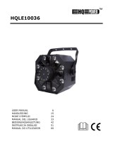
HQ Power ALISON I User manual

Category
Stroboscopes & disco lights
Type
User manual

This manual is also suitable for

V
A
A
A
A
A
U
S
G
E
N
O
M
A
B
E
V
DPL
3
LISON
I
LISON
I
LISON
I
LISON
I
LISON
I
S
ER MAN
E
BRUIKE
R
O
TICE D’
E
A
NUAL D
E
DIENUN
3
603
I
- 36 x
I
- 36 x
I
- 36 L
E
I
- 36 L
E
I
- 36 x
UA
L
R
SHAND
L
E
MPLOI
EL USUA
R
GSANLEI
T
MH
W
3W LE
D
3W LE
D
Ds DE
Ds DE
3W LE
D
L
EIDING
R
IO
T
UNG
W
11
D
s - DM
X
D
s - DM
X
3W - P
I
3W - C
O
D
s - DM
X
4
8
13
18
23
X
CONT
X
GEST
U
I
LOTAG
O
NTRO
L
X
-GEST
4
ROLLE
D
U
URD
E DMX
L
DMX
EUERT
D
VDPL3603MHW11
V. 01 – 31/01/2012 2 ©Velleman nv
1 moving head
2 yoke
3 carrying handle
4 control buttons
5 display
6 base
1 moving head
2 draagjuk
3 handvat
4 bedieningstoetsen
5 display
6 voet
1 projecteur lyre 1 moving head 1 Moving Head
2 palanche 2 yugo 2 Joch
3 poignée 3 empuñadura 3 Griff
4 boutons-poussoirs 4 botones de control 4 Einstellknöpfe
5 afficheur 5 pantalla 5 Display
6 base 6 base 6 Basis
7 power cord
8 fuse holder
9 DMX output
10 DMX output
11 safety eyelet
7 voedingskabel
8 zekering
9 DMX ingang
10 DMX uitgang
11 veiligheidsoog
7 cordon d’alimentation 7 cable de alimentación 7 Stromkabel
8 fusible 8 fusible 8 Sicherung
9 entrée DMX 9 entrada DMX 9 DMX-Eingang
10 sortie DMX 10 salida DMX 10 DMX-Ausgang
11 oeillet de sécurité 11 ojete 11 Öse
VDPL3603MHW11
V. 01 – 31/01/2012 3 ©Velleman nv
terminator
eindweerstand
résistance de
terminaison
terminación
Terminierung
How to turn the controller line from 3-pins into 5-pins (plug and socket).
Controller line van 3-pin naar 5-pin aanpassen (stekker en contact).
Modifier la ligne du contrôleur de 3 broches en 5 broches (fiche et contact).
Modificar la línea del controlador de 3 polos y 5 polos (conector y contacto).
Die Controller-Linie von 3-Pin nach 5-Pin anzupassen (Stecker und Kontakt).
© COPYRIGHT NOTICE
The copyright to this manual is owned by Velleman nv. All worldwide rights reserved.
No part of this manual or may be copied, reproduced, translated or reduced to any electronic medium or
otherwise without the prior written consent of the copyright holder.
© AUTEURSRECHT
Velleman nv heeft het auteursrecht voor deze handleiding. Alle wereldwijde rechten voorbehouden.
Het is niet toegestaan om deze handleiding of gedeelten ervan over te nemen, te kopiëren, te vertalen, te
bewerken en op te slaan op een elektronisch medium zonder voorafgaande schriftelijke toestemming van de
rechthebbende.
© DROITS D’AUTEUR
SA Velleman est l’ayant droit des droits d’auteur pour cette notice. Tous droits mondiaux réservés.
Toute reproduction, traduction, copie ou diffusion, intégrale ou partielle, du contenu de cette notice par quelque
procédé ou sur tout support électronique que se soit est interdite sans l’accord préalable écrit de l’ayant droit.
© DERECHOS DE AUTOR
Velleman NV dispone de los derechos de autor para este manual del usuario. Todos los derechos
mundiales reservados.
Está estrictamente prohibido reproducir, traducir, copiar, editar y guardar este manual del usuario o partes de
ello sin previo permiso escrito del derecho habiente.
© URHEBERRECHT
Velleman NV besitzt das Urheberrecht für diese Bedienungsanleitung. Alle weltweiten Rechte
vorbehalten.
Ohne vorherige schriftliche Genehmigung des Urhebers ist es nicht gestattet, diese Bedienungsanleitung ganz
oder in Teilen zu reproduzieren, zu kopieren, zu übersetzen, zu bearbeiten oder zu speichern.
V.
1
.
T
o
I
m
Th
If
t
F
o
w
w
T
h
D
u
In
o
v
A
n
b
e
2
.
01 – 31/01/2
.
Introd
u
o
all reside
n
m
portant e
n
This
har
m
shou
distri
If in
ank you for
t
he device
w
o
r more inf
o
w
w.hqpow
e
h
is device
n
u
st inside t
h
spect abo
v
v
erheating
o
n
yone inte
n
e
fore conti
n
.
Safety
Be
Al
w
ar
e
Ke
C
a
D
o
Th
an
This devic
e
qualified p
Make sure
Do not cri
m
necessary
.
Respect a
Use an ap
p
012
u
ction
n
ts of the
E
n
vironmen
t
symbol on t
h
m
the enviro
n
ld be taken
t
butor or to
a
doubt, co
n
choosing H
Q
w
as damage
d
o
concerni
n
e
r.eu.
n
eeds perio
h
e unit mu
s
v
e points b
e
o
r fire and
n
ding to in
s
n
uing. Kee
p
Instruc
t
very carefu
w
ays discon
n
e
performed
ep this devi
c
a
ution: devi
c
o
not stare
epileptic s
e
temporaril
y
permanen
t
ere are no
u
d/or spare
p
e
falls unde
r
erson carry
that the av
a
m
p the pow
e
.
minimum di
p
ropriate sa
f
E
uropean U
n
t
al informa
t
h
e device o
r
n
ment. Do n
t
o a speciali
a
local recy
c
n
tact your l
Q
Power™! P
l
d
in transit,
n
g this pro
d
dical main
t
s
t be remo
v
e
fore each
o
warranty
w
s
tall or ope
p
this man
u
t
ions
l during the
n
ect mains
p
. Handle th
e
c
e away fro
m
c
e heats up
directly at
e
izure in se
n
y
loss of sig
t
(irreversibl
u
ser-service
a
p
arts.
r
protection
c
out the ele
c
a
ilable volta
g
e
r cord and
p
stance of 0.
f
ety cable t
o
VD
P
Us
e
n
ion
t
ion about
t
r
the packag
ot dispose
o
zed compan
c
ling service
.
ocal waste
l
ease read t
h
don't install
d
uct and th
IMPORTA
N
t
enance.
v
ed. Ventil
o
peration.
w
ill be void
rate this d
e
u
al with th
e
installation
:
p
ower when
e
power cor
d
m
children a
during use.
the light s
o
n
sitive peopl
ht (flash bli
n
e) eye dam
a
a
ble parts in
c
lass I. It is
c
tric connect
g
e does not
p
rotect it ag
5 m betwee
o
fix the dev
i
P
L3603MH
W
4
e
r ma
n
t
his produ
c
e indicates
t
o
f the unit (
o
y for recycli
.
Respect th
e
disposal a
h
e manual t
h
or use it an
e latest ve
r
N
T SAFETY
ation hole
s
Not respe
c
.
e
vice must
e
device fo
r
:
touching li
v
device not i
d
by the plu
g
nd unautho
r
o
urce, as t
h
e
n
dness)
a
ge
side the de
v
therefore e
s
ion.
exceed the
ainst dama
g
n the devic
e
i
ce (e.g. VD
W
11
n
ual
c
t
t
hat disposa
o
r batteries)
ng. This de
v
e
local envi
r
uthorities.
h
oroughly b
e
d contact y
o
r
sion of thi
WARNING
s
must be
k
c
ting these
read and
c
r
future ref
e
v
e wires ca
n
n use or wh
e
g
only.
r
ized users.
h
is may cau
s
v
ice. Refer t
o
s
sential that
voltage sta
t
g
e. Have an
e
’s light out
p
LSC7 or V
D
l of the devi
as unsorte
d
v
ice should
b
r
onmental r
u
e
fore bringi
n
o
ur dealer.
s manual,
p
k
ept clean.
warnings
m
c
learly und
e
e
rence.
n
cause life-
t
e
n servicing
s
e
o
an authori
z
the device
b
t
ed in the sp
authorised
d
p
ut and any
i
D
LSC8).
ce after its l
d
municipal
w
b
e returned
t
u
les.
n
g this devi
c
p
lease visi
t
m
ay result
e
rstand thi
s
t
hreatening
e
or mainten
a
z
ed dealer f
o
b
e earthed.
ecifications
d
ealer repla
c
i
lluminated
s
©Vellema
n
ifecycle cou
l
w
aste; it
t
o your
c
e into servi
c
t
our webs
i
in
s
manual
e
lectroshoc
k
a
nce activiti
e
o
r service
Have a
of this man
u
c
e it if
s
urface.
n
nv
l
d
c
e.
i
te
k
s.
e
s
u
al.
V.
3
.
Re
4
.
5
.
a.
01 – 31/01/2
.
Gener
a
fer to the V
e
Familiaris
e
unqualifie
d
device.
All modific
the device
Only use t
lamp expl
o
Damage c
a
dealer will
A qualified
Do not sw
i
device ag
a
This devic
e
used indo
o
Lighting e
f
Use the or
Keep this
m
.
Featur
e
digital dis
p
DMX cont
r
stand-alo
wide rang
e
1-10Hz st
r
master di
m
.
Install
a
Overhea
d
Risk
deter
regul
a
instal
Have the
d
The const
r
device for
The install
a
Never sta
n
technician
Install the
For truss-
m
(folded) b
r
Adjust the
012
a
l Guidel
i
e
lleman®
S
Indoor us
Respect a
m
surface. N
e
Keep this
d
at all time
s
Protect thi
s
e
yourself wi
d
people. An
ations of th
e
is not cove
r
he device fo
o
sion, crash
,
a
used by di
s
not accept
r
technician
s
i
tch the devi
a
inst damag
e
e
is designe
d
o
rs (< 45°
C
f
fects are n
o
iginal packa
m
anual for
f
e
s
p
lay for eas
y
r
olled by 12
c
n
e mode wit
h
e
, horizontal
r
obe effect
m
mer functi
o
a
tion
d
mounting
of injury.
O
mining the i
a
rly. Do not
lation may
r
d
evice instal
r
uction to w
h
one hour wi
a
tion must
a
n
d directly b
e
check the d
device in a
m
ounting, u
s
r
acket.
desired incl
i
nes
S
ervice an
d
e only. Kee
m
inimum di
s
e
ver use ne
a
d
evice away
s
. For suffici
e
s
device fro
m
th the funct
i
y damage t
h
e
device are
r
ed by the
w
r its intend
e
,
etc. Using
t
s
regard of c
e
r
esponsibilit
y
s
hould insta
ce on imme
e
by leaving
d
for profes
s
C
, < 50%RH
)
o
t designed
f
ging if the d
f
uture refere
y
configurati
o
c
hannels
h
built-in pr
o
angle of 5
4
o
n 0-100%.
O
verhead m
o
nstallation
m
attempt to
i
r
esult in inju
led by a qu
a
h
ich the dev
i
thout defor
m
a
lways be s
e
e
low the de
v
evice once
a
location wit
h
s
e an appro
p
ination angl
VD
P
d
Q
uality
W
p this devic
e
s
tance of 0.
5
a
r flammabl
e
from dust a
e
nt air circul
m
shocks an
d
i
ons of the
d
h
at may occ
forbidden f
o
w
arranty.
e
d purpose.
A
t
he device i
n
e
rtain guidel
y
for any en
ll and servi
c
diately afte
r
it switched
s
ional use o
n
)
with an al
t
f
or permane
n
evice is to
b
nce.
o
n, can be r
e
o
grams, incl
u
4
0° and vert
i
o
unting req
u
m
aterial to b
i
nstall the d
e
ries.
a
lified perso
n
i
ce is attach
m
ation.
e
cured with
a
v
ice when it
a
year and
o
h
few passe
r
p
riate clam
p
e via the m
o
P
L3603MH
W
5
W
arranty on
e
away for
m
5
m between
e
products o
nd extreme
ation, leave
d
abuse. Av
o
d
evice befor
e
ur will most
o
r safety re
a
A
ll other us
e
n
an unauth
o
ines in this
m
suing defec
t
c
e this devic
e
r
it has been
off until it h
a
n
stage, in d
t
ernating cu
r
n
t operation
b
e transport
e
e
versed for
u
ding music
i
cal of 270°,
u
ires extensi
e used… Ha
v
e
vice yours
e
n
, respectin
g
ed should b
e
a
secondary
is being mo
o
nce before
y
r
s-by and in
a
p
(not incl.)
a
o
unting bra
c
W
11
the last pa
g
m
rain, moist
u
the device
s
r
in explosi
v
heat. Make
at least 1”
(
o
id brute fo
r
e
actually u
s
probably b
e
a
sons. Dam
a
e
s may lead
o
rised way
w
m
anual is n
o
t
s or proble
m
e
.
exposed to
a
s reached
r
iscos, theat
r
r
rent of 230
: regular op
e
d.
180°, auto
s
control fun
c
in 8- or 16
-
ve experien
c
v
e the mate
e
lf if you lac
k
g
EN 60598-
e
able to su
p
attachmen
t
unted, rem
o
y
ou bring it
i
a
ccessible t
o
a
nd fit an M
1
c
ket and tig
h
g
es of this
m
u
re, splashi
n
s
’ light outp
u
v
e atmosphe
sure the ve
n
(
± 2.5 cm)
i
r
ce when op
e
s
ing it. Do n
o
e
due to unp
a
ge caused
b
to short cir
c
w
ill void the
o
t covered b
m
s.
changes in
r
oom tempe
r
es, etc. Th
e
VAC~50 Hz
eration bre
a
s
witch off af
t
c
tion
-
bit mode
c
e: calculati
rial and the
k
these qual
2-17 and al
l
p
port 10 tim
t
e.g. a safe
t
o
ved or serv
i
nto service.
o
unauthoris
1
0 bolt thro
u
h
ten the bra
c
m
anual.
n
g and drip
p
u
t and any il
l
res.
n
tilation op
e
i
n front of t
h
e
rating the
d
o
t allow ope
rofessional
u
b
y user mod
i
c
uits, burns,
warranty.
y the warra
n
temperatur
e
rature.
e
VDPL3603
M
.
a
ks will prol
o
t
er 30 sec.
ng workloa
d
device itsel
f
ifications as
l
other appli
c
es the weig
h
t
y cable [11
iced. Have
a
ed persons.
u
gh the cen
t
c
ket screws.
©Vellema
n
p
ing liquids.
l
uminated
e
nings are cl
e
h
e openings.
d
evice.
ration by
u
se o
f
the
i
fications to
electroshoc
n
ty and the
e
. Protect th
M
HW11 can
o
ng their liv
e
d
limits,
f
checked
improper
c
able norm
s
h
t of the
].
a
qualified
t
re of the
n
nv
e
ar
ks,
e
be
e
s.
s
.
VDPL3603MHW11
V. 01 – 31/01/2012 6 ©Velleman nv
b. DMX-512 connection
When applicable, connect an XLR cable to the female 3-pin XLR output of a controller (not incl.) and the
other side to the male 3-pin XLR input [9] of the VDPL3603MHW11. Multiple VDPL3603MHW11’s can be
linked through serial linking. The linking cable should be a dual core, screened cable with XLR input and
output connectors.
Maximum recommended serial data link distance is 500 meters (1640 ft). Maximum recommended number
of fixtures on a serial data link is 32 fixtures.
A DMX terminator is recommended for installations where the DMX cable has to run a long distance or is in
an electrically noisy environment (e.g. discos). The terminator prevents corruption of the digital control
signal by electrical noise. The DMX terminator is simply an XLR plug with a 120 resistor between pins 2
and 3, which is then plugged into the XLR output socket [10] of the last device in the chain.
c. General
Make sure there is no flammable material within a 50cm radius of the device and there is sufficient cooling.
Have a qualified electrician carry out the electrical connection.
Connect the device to the mains with the power plug. All fixtures must be powered directly off a grounded
switched circuit and cannot be run off a rheostat or dimmer circuit, even if the rheostat or dimmer channel
is used solely for 0% to 100% switch.
The installation has to be approved by an expert before the device is taken into service.
d. Replacing the fuse [8]
Only replace the fuse by a fuse of the same type and rating.
1. Before replacing the fuse, unplug the mains lead.
2. Unscrew the fuse holder on the rear panel of the base with an appropriate screwdriver.
3. Remove the old fuse and install the new fuse in the fuse holder.
4. Replace the fuse holder in the housing and tighten it.
6. Operation
Refer to the illustrations on page 2 of this manual.
a. Control Panel Navigation
Access the control panel functions using the four panel buttons [4] located directly underneath the
display [5]. From left to right:
button function
<MODE> used to access the menu or to return to a previous menu option
<ENTER> used to select and store the current menu or option within the menu
<UP> scrolls through the menu options in ascending order
<DOWN> scrolls through the menu options in descending order
The control panel display shows the menu items you select from the menu map. To select a menu item,
press <ENTER>.
Use the <UP> and <DOWN> buttons to navigate the menu map and menu options. Press <ENTER> to
access the menu function currently displayed or to enable a menu option. To return to the previous option
or menu without changing the value, press the <MODE> button.
b. Menu Functions
function display description
DMX-mode <Addr> <A001>
<A512>
Set DMX starting address between 1 and 512.
pan <PAn> <No> pan normal
<Yes> pan inverse
tilt <tilt> <No> tilt normal
<Yes> tilt inverse
VDPL3603MHW11
V. 01 – 31/01/2012 7 ©Velleman nv
function display description
play <PLAY> <At01>
<At02>
auto program 1-2
<Sn01>
<Sn02>
sound controlled mode 1-2
<dnCo> DMX controlled mode
<SLAE> slave mode
manual
control
<Man> <CH01>
<CH12>
<d000>
<d255>
Select the setting for each channel.
display <dISP> <No> normal display
<Yes> 180° rotated display
reset <rEST> <FACt> Press <Enter> for 5 seconds to reset all settings except the
DMX starting address.
<Moto> Press <Enter> for 5 seconds to reset all settings including the
DMX starting address.
c. DMX Mode
This mode allows you to control the fixture by any universal DMX controller.
All DMX-controlled devices need a digital start address so that the correct device responds to the signals.
This digital start address is the channel number from which the device starts to “listen” to the DMX
controller. The same starting address can be used for a whole group of devices or an individual address can
be set for every device.
When all devices have the same address, all the units will “listen” to the control signal on one particular
channel. In other words: changing the settings of one channel will affect all devices simultaneously. If you
set individual addresses, each device will “listen” to a separate channel number. Changing the settings of
one channel will only affect the device in question.
In case of the 12-channel VDPL3603MHW11, you will have to set the start address of the first unit to 1
(CH1~12), the second unit to 13 (1 + 12) (CH13~24), the third to 25 (13 + 12) (CH25~36), and so on.
Press <MODE> until <Addr> is displayed.
Use <UP> or <DOWN> to set the DMX starting address (A001~A512). Press <Enter> to confirm.
d. DMX Channel Values
channel function from to description
1 shutter/strobe
0 6 shutter closed
7 255 strobe slow -> fast
2 dimmer 0 255 master dimmer, 0-100%
3 colour
0 4 white
5 9 red
10 14 orange
15 19 yellow
20 24 green
25 29 light blue
30 34 blue
35 39 magenta
40 49 rose
50 150 colour change function 1
151 200 rose
201 255 colour change function 2
4 colour change speed 0 255 slow -> fast
5 pan 0 255 rotate head horizontally (127 = neutral)
6 tilt 0 255 move head vertically (127 = neutral)
7 pan fine 0 255 rotate head horizontally – small increments
8 tilt fine 0 255 move head vertically – small increments
V.
9
10
11
12
7
.
8
.
po
po
nu
be
co
l
D
M
di
m
w
e
fu
s
U
s
of
F
o
w
w
T
h
1
.
A
a
B
e
H
e
D
a
be
V
o
w
w
01 – 31/01/2
n
r
e
g
b
.
Cleani
n
The intern
a
the exact
s
All screws
The housi
n
trussing)
s
supports,
d
Mechanica
The electri
device.
Regularly
r
There are
.
Techni
c
wer supply
wer consu
m
mber of LE
D
am angle
l
our temper
a
M
X channels
m
ensions
e
ight
s
e
s
e this devi
damage o
r
o
r more inf
o
w
w.hqpow
e
h
e informa
t
.
Inleidi
n
a
n alle ing
e
e
langrijke
m
Dit s
y
weg
g
batt
e
tere
c
bren
g
e
bt u vrage
a
nk u voor u
w
schadigd tij
d
o
or meer in
w
w.hqpow
e
012
o function
e
d LEDs
reen LEDs
lue LEDs
ng
and
m
a
l circuit is
p
s
pecification
should be ti
n
g, the lens
e
s
hould not b
e
d
o not chan
g
lly moving
p
c power su
p
r
emove dus
t
no user-ser
v
c
al Spec
i
m
ption
D
s
a
ture
ce with ori
r
injury res
o
concerni
n
e
r.eu.
t
ion in this
ng
e
zetenen v
a
m
ilieu-info
r
y
mbool op
h
g
eworpen, d
e
rijen) niet
b
c
htkomen v
o
g
en. Respe
c
n, contact
e
w
aankoop!
d
ens het tra
formatie o
v
e
r.eu.
m
aintena
p
rotected b
y
s.
ght and fre
e
e
s, the mou
n
e
deformed,
g
e the locati
p
arts must n
p
ply cables
m
t
from the h
o
v
iceable par
t
i
fication
230V
A
185W
12 x r
e
25°
5600K
12
242 x
4.5kg
2A / 2
3
ginal acce
s
ulted from
n
g this pro
d
manual is
s
G
e
a
n de Euro
p
r
matie bet
r
h
et toestel o
f
it toestel sc
h
b
ij het gewo
n
o
or recyclag
e
c
teer de pla
a
e
er dan de
Lees deze
h
nsport, inst
a
v
er dit pro
d
VD
P
0
2
0
2
0
2
nce
y
a 250V/50
0
e
of corrosio
n
n
ting suppo
r
modified o
r
on o
f
the c
o
ot show an
y
m
ust not sh
o
o
using and
t
t
s inside. R
e
s
A
C ~ 50Hz
e
d; 12 x gre
234 x 295m
3
0VAC (FF2
s
sories onl
y
(incorrect
)
d
uct and th
s
ubject to
c
e
bruik
e
p
ese Unie
r
effende di
t
f
de verpak
k
h
ade kan to
e
n
e huishoud
e
. U moet di
a
tselijke mili
e
plaatselijk
e
h
andleiding
g
a
lleer het da
d
uct en de
P
L3603MH
W
8
no
2
55 di
m
2
55 di
m
2
55 di
m
0
mA, 5 x 20
n
.
r
ts and the i
n
r
tampered
w
o
nnections…
y
signs of w
e
o
w any dam
a
t
he air vent
s
e
fer to an au
en; 12 x bl
u
m
N)
y
. Vellema
n
)
use of thi
e latest ve
r
c
hange wit
e
rsha
n
t
product
k
ing geeft a
a
e
brengen a
a
elijke afval;
t toestel na
a
e
uwetgevin
g
e
autoritei
t
g
rondig voo
r
n niet en ra
a
laatste ve
r
W
11
function
m
mer 100%
m
mer 100%
m
mer 100%
mm fuse [
8
n
stallation l
o
w
ith e.g. do
e
ar and tear
.
a
ge. Have a
s
using a sli
g
thorized de
a
u
e (3W)
n
nv canno
t
s device.
r
sion of thi
hout prior
n
dleidi
a
n dat, als h
n het milie
u
het moet bi
a
r uw verdel
g
.
t
en betreff
e
r
u het toest
e
a
dpleeg uw
r
sie van de
z
-> 0%
-> 0%
-> 0%
8
]. Replace
a
o
cation (e.g.
not drill ext
r
.
qualified te
c
g
htly damp
c
a
ler for serv
i
t
be held r
e
s manual,
p
notice.
ng
et na zijn le
v
u
. Gooi dit t
o
j een gespe
c
er of naar e
e
e
nd de ver
w
e
l in gebrui
k
dealer.
z
e handlei
d
a
faulty fus
e
ceiling, sus
r
a holes in
m
c
hnician mai
c
loth.
i
ce and/or s
p
e
sponsible
i
p
lease visi
t
v
enscyclus
w
o
estel (en e
v
c
ialiseerd b
e
e
n lokaal re
c
w
ijdering.
k
neemt. W
e
d
ing, zie
©Vellema
n
e
by a fuse
o
pension,
m
ounting
ntain the
p
are parts.
i
n the eve
n
t
our webs
i
w
ordt
v
entuele
e
drijf
c
yclagepunt
rd het toest
n
nv
o
f
n
t
i
te
el
V.
R
e
v
e
L
e
o
v
Ie
h
a
2
.
3
.
Ra
01 – 31/01/2
e
inig dit to
e
e
ntilatieop
e
e
ef bovenst
v
erverhitti
n
dereen die
a
ndleiding
v
.
Veili
g
h
e
We
ele
Tr
e
he
t
Ho
u
Le
t
Kij
k
te
v
Er
z
res
Dit toestel
geschoold
e
De beschi
k
handleidin
g
De voedin
g
plaatsen.
Zorg voor
Maak het
t
.
Al
g
em
e
adpleeg de
V
Leer eerst
toestel nie
Om veilig
h
aangebrac
Gebruik h
e
brandwon
d
012
e
stel regel
m
e
ningen sc
h
aande veil
i
n
g van het
t
dit toestel
v
oor verde
r
e
idsinst
r
es voorzich
t
ktroshocks
t
e
k de stekke
t
niet gebrui
k
u
d dit toest
e
t
op: dit toe
k
niet recht
s
epilepsieaa
tijdelijke bl
permanent
e
v
ermijden.
z
ijn geen d
o
erveonderd
e
valt onder
b
e
technicus
m
k
bare netsp
a
g
.
g
skabel ma
g
een minimu
t
oestel vast
e
ne rich
t
V
elleman
®
Gebruik
h
vloeistof
f
Zorg vo
o
belichte
o
omgevin
g
Bescher
m
geraken.
Bescher
m
de functies
t gebruiken
.
h
eidsredene
n
ht valt niet
o
e
t toestel en
d
en, elektris
m
atig. Ver
w
h
oon.
i
gheidsinst
t
oestel en
b
installeer
t
r
e raadple
g
r
ucties
t
ig bij de ins
t
e vermijde
n
r uit het sto
p
k
t.
e
l uit de buu
stel wordt z
e
s
treeks in d
e
nvallen bij
g
indheid (flit
s
e
en onherr
o
o
or de gebru
e
len, contac
t
b
eschermin
g
m
oet de ele
k
a
nning mag
g
niet besch
a
mafstand v
a
met een ge
s
t
li
j
nen
service- e
n
h
et toestel
e
f
en.
o
r een mini
m
o
ppervlak G
g
en.
m
tegen sto
f
Voorzie ee
n
m
tegen sch
o
van het toe
s
.
Meestal is
b
n
mag u gee
o
nder de ga
kel waarvo
o
che schokk
e
VD
P
BELANGRI
w
ijder alle
s
ructies na
v
b
rand. In d
t
of gebrui
k
g
ing.
tallatie: raa
k
n
.
p
contact (tr
e
rt van kind
e
e
er warm tij
e
lichtbron o
m
g
evoelige pe
s
blindheid)
o
epelijke sc
h
iker vervan
g
t
eer uw dea
l
g
sklasse I,
w
k
trische aan
niet hoger z
a
digd zijn of
a
n 0,5 m tu
s
s
chikte veili
g
n
kwaliteit
s
e
nkel binn
e
m
umafstand
v
ebruik nooit
f
en extrem
e
n
ruimte va
n
o
kken en ve
s
tel kennen
b
eschadigin
g
n wijziginge
rantie.
o
r het gema
a
e
n, enz. Bij
o
P
L3603MH
W
9
JKE WAAR
S
s
tof binne
n
v
oor elk g
e
it geval ve
r
k
t, moet de
k
geen kabe
e
k niet aan
d
e
ren en onb
e
dens het ge
m
rsonen
h
ade aan de
g
bare onder
d
l
er.
w
at wil zegg
e
sluiting ver
z
ijn dan de s
ingekort w
o
s
sen de licht
g
heidskabel
s
garantie a
e
nshuis. Be
s
v
an 0,5 m t
u
in de nabij
h
e
hitte. Zorg
n
minstens 2
rmijd brute
voor u het
g
g
het gevolg
n aanbreng
e
a
kt is. Ande
r
o
noordeelku
W
11
S
CHUWIN
G
n
in het toe
s
e
bruik. Nal
a
r
valt de ga
r
ze handlei
d
ls aan die o
n
d
e kabel!) v
o
e
voegden.
bruik.
ogen
d
elen in dit
t
e
n dat het t
o
z
orgen.
panning in
d
o
rden. Laat
u
uitgang van
(bv. VDLSC
c
hteraan de
z
s
cherm teg
e
u
ssen de lic
h
h
eid van ont
dat de verl
u
,5 cm tusse
kracht tijde
n
g
aat gebruik
van onprof
e
e
n. Schade
d
r
e toepassin
g
n
dig gebrui
k
G
s
tel en hou
d
a
tig onder
h
r
antie.
d
ing gelez
e
n
der stroom
o
ordat u he
t
t
oestel. Voo
r
o
estel geaar
d
d
e specificat
i
u
w dealer z
o
het toestel
7 of VDLS
C
z
e handleidi
e
n regen, vo
c
h
tuitgang v
a
vlambare p
r
u
chtingsope
n
n het toeste
n
s de bedie
n
en. Ongesc
h
e
ssioneel g
e
d
oor wijzigi
n
g
en kunnen
k
vervalt de
d
de
h
oud kan le
e
n hebben.
staan om d
t
toestel rei
n
r
onderhoud
d
moet zijn.
i
es achteraa
o
nodig een
n
en het belic
h
C
8).
ng.
c
htigheid en
a
n het toest
e
r
oducten of i
n
ingen niet
v
l en elk and
e
n
ing.
h
oolde pers
o
e
bruik.
n
gen die de
g
leiden tot k
o
garantie.
©Vellema
n
iden tot
Bewaar d
e
odelijke
n
igt en als u
of
Een
n de
n
ieuwe kab
e
h
te oppervl
a
opspattend
e
l en het
n explosiev
e
v
erstopt
e
r object.
o
nen mogen
g
ebruiker h
e
o
rtsluitinge
n
n
nv
e
e
l
a
k.
e
e
dit
e
eft
n
,
VDPL3603MHW11
V. 01 – 31/01/2012 10 ©Velleman nv
De garantie geldt niet voor schade door het negeren van bepaalde richtlijnen in deze handleiding en uw
dealer zal de verantwoordelijkheid afwijzen voor defecten of problemen die hier rechtstreeks verband mee
houden.
Laat dit toestel installeren en onderhouden door een geschoolde technicus.
Om beschadiging te vermijden, zet u het toestel best niet aan onmiddellijk nadat het werd blootgesteld aan
temperatuurschommelingen. Wacht tot het toestel op kamertemperatuur gekomen is.
Dit toestel is ontworpen voor professioneel gebruik op podia, in disco's, enz. U mag dit toestel enkel
binnenshuis gebruiken (<45°C, <50%RH). Sluit aan op 230 VAC~50 Hz.
Lichteffecten zijn niet ontworpen voor continue werking: regelmatige onderbrekingen doen ze langer
meegaan.
Gebruik de oorspronkelijke verpakking wanneer u het toestel vervoert.
Bewaar deze handleiding voor verdere raadpleging.
4. Eigenschappen
LCD-scherm voor een gemakkelijke menu-instelling, kan 180° gedraaid worden, automatische uitschakeling
na 30 sec.
DMX gestuurd via 12 kanalen
autonome modus met ingebouwde programma's, en muziekgestuurde functie
breed bereik, horizontale hoek van 540°, verticale hoek van 270°, 8- of 16-bit mode
1-10Hz stroboscoopeffect
master dimmer functie 0~100%.
5. Installatie
a. Het toestel monteren
Gevaar voor verwondingen. Een degelijke praktijkervaring is vereist voor de plaatsing van dit
toestel. U moet de maximumbelasting van de draagconstructie kunnen berekenen, weten welk
constructiemateriaal u kunt gebruiken en u moet het gebruikte materiaal en het toestel af en toe
laten nakijken. Monteer het toestel niet zelf indien u er geen ervaring mee heeft. Een slechte
montage kan leiden tot verwondingen.
Laat een geschoolde technicus dit toestel installeren conform EN 60598-2-17 en andere toepasselijke
normen.
De constructie waaraan het toestel wordt bevestigd, moet gedurende 1 uur 10 x het gewicht van dit toestel
kunnen dragen zonder te vervormen.
Maak het toestel ook vast met een veiligheidskabel [11].
Sta nooit recht onder het toestel wanneer u het monteert, verwijdert of schoonveegt. Laat het toestel
controleren door een geschoolde technicus voor u het in gebruik neemt en laat het 1 x per jaar volledig
nakijken.
Installeer dit toestel op een plaats waar niemand langs moet lopen, kan neerzitten of het toestel kan
aanraken.
Voor de montage op een lichtbrug, gebruik een geschikte klem (niet meegelev.) en draai een M10 bout
doorheen het midden van de (geplooide) beugel.
Regel de gewenste invalshoek door middel van de montagebeugel en draai de regelschroeven stevig aan.
b. DMX512-aansluiting
Indien van toepassing, sluit een XLR-kabel aan de vrouwelijke 3-pin XLR-uitgang van een controller (niet
meegelev.) en de andere kant van de mannelijke 3-pin XLR-ingang [9] van de VDPL3603MHW11. U kunt
verscheidene VDPL3603MHW11’s aan elkaar koppelen met behulp van een seriële koppeling. Gebruik
daarvoor een 2-aderige afgeschermde kabel met XLR ingang- en uitgangsaansluitingen.
De maximaal aanbevolen kabellengte is 500 meter, het aanbevolen maximumaantal toestellen op eenzelfde
aansluiting is 32.
Een DMX eindweerstand is aanbevolen als de DMX-kabel vrij lang is of wordt gebruikt in een omgeving met
veel elektrische ruis (bv. een discotheek). De eindweerstand voorkomt corruptie van het digitale
controlesignaal door elektrische ruis. De DMX eindweerstand is niets meer dan een XLR-stekker met een
weerstand van 120 van pin 2 naar 3. Deze XLR-stekker wordt dan aangesloten op de XLR-uitgang [10]
van het laatste toestel in de reeks.
c. Algemeen
Verwijder alle brandbaar materiaal in een straal van 0,5 m rond het toestel en voorzie voldoende koeling.
Een geschoolde elektricien moet het toestel aansluiten.
VDPL3603MHW11
V. 01 – 31/01/2012 11 ©Velleman nv
Sluit het toestel via de stekker aan op het lichtnet. Alle toestellen moet via een geaard stopcontact gevoed
worden en mogen niet via een variabele weerstand of dimcircuit gevoed worden, ook al gebruikt u de
variabele weerstand of het dimcircuit als een 0% tot 100% inschakeling.
De installatie moet voor het eerste gebruik gekeurd worden door een expert.
d. De zekering vervangen [8]
Vervang een zekering met een zekering van hetzelfde type en met dezelfde waarden.
1. Ontkoppel het toestel van het lichtnet voor u de zekering vervangt.
2. Maak de zekeringhouder los achteraan de voet met een gepaste schroevendraaier.
3. Verwijder de oude zekering en vervang hem door een nieuwe.
4. Plaats de zekeringhouder en maak deze vast.
6. Gebruik
Raadpleeg de afbeelding op pagina 2 van deze handleiding.
a. Het bedieningspaneel
Bedien het paneel met behulp van de vier toetsen [4] onderaan de leddisplay [5]. Van links naar rechts:
toets functie
<MODE> toegang tot het menu of terugkeer naar het vorige menu
<ENTER> selectie en bevestiging van een optie
<UP> scroll door de verschillende menuopties in stijgende volgorde
<DOWN> scroll door de verschillende menuopties in dalende volgorde
De geselecteerde menufunctie wordt op de leddisplay weergegeven. De leddisplay geeft ook de
eerstvolgende menuoptie onder de functie weer. Selecteer een menuoptie met <ENTER>.
Scroll doorheen het menu met <UP> en <DOWN>. Selecteer de menufunctie met <ENTER> en druk op
<MODE> om naar het hoofdmenu terug te keren zonder de waarde te hebben gewijzigd.
b. Hoofdmenu-functies
functie display omschrijving
DMX-modus <Addr> <A001>
<A512>
Stel het DMX startadres in tussen 1 en 512.
pan <PAn> <No> normale panbeweging
<Yes> omgekeerde panbeweging
tilt <tilt> <No> normale tiltbeweging
<Yes> omgekeerde tiltbeweging
afspelen <PLAY> <At01>
<At02>
automatische modus 1-2
<Sn01>
<Sn02>
geluidsgestuurde modus 1-2
<dnCo> DMX-sturing
<SLAE> slavemodus
handmatige
aansturing
<Man> <CH01>
<CH12>
<d000>
<d255>
Selecteer de instelling voor elk kanaal.
display <dISP> <No> normale modus
<Yes> display 180° gedraaid
resetten <rEST> <FACt> Druk op <Enter> gedurende 5 seconden om alle instellingen
terug te zetten op nul behalve het DMX startadres.
<Moto> Druk op <Enter> gedurende 5 seconden om alle instellingen
terug te zetten op nul inclusief het DMX startadres.
VDPL3603MHW11
V. 01 – 31/01/2012 12 ©Velleman nv
c. DMX-sturing
Sturing van het toestel via een universele DMX-controller.
Alle DMX-gestuurde toestellen hebben een digitaal startadres nodig, zodat het juiste toestel reageert op de
signalen. Dit digitale startadres is het kanaalnummer van waarop het toestel ‘luistert’ naar het signaal van
de DMX controller. U kunt één enkel startadres gebruiken voor een groep toestellen of u kunt per toestel
een nieuw startadres ingeven.
Wanneer u een enkel startadres instelt, zullen alle toestellen ‘luisteren’ naar hetzelfde kanaal. Met andere
woorden: wanneer u de instellingen voor 1 kanaal verandert, zullen alle toestellen er tegelijk op reageren.
Wanneer u verschillende adressen instelt, dan luistert elk toestel naar een ander kanaal. Met andere
woorden: wanneer u de instellingen van een kanaal verandert, zal enkel het toestel op dat kanaal reageren.
In het geval van de 12-kanaals VDPL3603MHW11, zult u het startadres van het eerste toestel op 1
(CH1~12) moeten instellen, van het tweede toestel op 13 (1 + 12) (CH13~24), van het derde op 25
(13 + 12) (CH25~36), enz.
Druk op <MODE> tot <Addr> op de display verschijnt.
Stel het startadres (A001~A512) in met <UP> en <DOWN> en druk op <Enter> om te bevestigen.
d. DMX-waarden per kanaal
kanaal functie van tot omschrijving
1 sluiter/stroboscoop
0 6 sluiter dicht
7 255 stroboscoop traag -> snel
2 dimmer 0 255 master dimmer, 0-100%
3 kleur
0 4 wit
5 9 rood
10 14 oranje
15 19 geel
20 24 groen
25 29 lichtblauw
30 34 blauw
35 39 magenta
40 49 roze
50 150 functie kleurenovergang 1
151 200 roze
201 255 functie kleurenovergang 2
4
snelheid
kleurenovergang
0 255 traag -> snel
5 pan 0 255 draai kop horizontaal (127 = neutraal)
6 tilt 0 255 beweeg kop verticaal (127 = neutraal)
7 pan fijn 0 255 draai kop horizontaal – kleine stappen
8 tilt fijn 0 255 beweeg kop verticaal – kleine stappen
9 geen functie geen functie
10 rode leds 0 255 dimmer 100% -> 0%
11 groene leds 0 255 dimmer 100% -> 0%
12 blauwe leds 0 255 dimmer 100% -> 0%
7. Reiniging en onderhoud
Het interne circuit is beveiligd door een interne zekering [8] van 250 V/500 mA, 5 x 20 mm. Vervang een
defecte zekering door een exemplaar met dezelfde eigenschappen.
Alle gebruikte schroeven moeten goed zijn aangespannen en mogen geen sporen van roest vertonen.
De behuizing, de lenzen, de montagebeugels en de montageplaats (bv. het plafond of het gebinte) mogen
niet vervormd zijn of aangepast worden (geen extra gaten in montagebeugels, aansluitingen niet
verplaatsen etc.)
Mechanisch bewegende delen mogen geen sporen van slijtage vertonen en mogen niet onregelmatig
bewegen.
De voedingskabels mogen niet beschadigd zijn. Laat het toestel onderhouden door een geschoolde
technicus.
V.
8
.
vo
ve
aa
st
r
kl
e
D
M
af
m
ge
ze
k
G
e
k
w
V
o
w
w
D
e
k
e
1
.
A
u
D
e
E
n
N
o
l’a
p
P
o
si
t
N
e
E
n
R
e
su
T
o
pr
2
.
01 – 31/01/2
Verwijder
U mag ge
e
.
Techni
s
eding
rbruik
ntal leds
r
alingshoek
e
urtemperat
u
M
X-kanalen
m
etingen
wicht
k
ering
e
bruik dit t
o
w
etsuren b
i
o
or meer in
w
w.hqpow
e
e
informati
e
e
nnisgevin
g
.
Introd
u
u
x résident
s
e
s informa
t
Ce s
y
pollu
e
parm
Renv
o
resp
e
n
cas de qu
e
o
us vous re
m
p
pareil. Si l’
a
o
ur plus d’i
n
t
e web ww
w
e
ttoyer rég
u
n
lever la p
o
e
specter ce
rchauffe d
e
o
ute perso
n
éalable. C
o
.
Consi
gn
Ê
tr
e
mo
b
l'a
p
012
regelmatig
h
e
n onderdel
e
s
che sp
e
u
ur
o
estel enk
e
i
j (verkeer
d
formatie o
v
e
r.eu.
e
in deze h
a
g
.
u
ction
s
de l'Unio
n
t
ions envir
o
y
mbole sur l'
e
r l'environ
n
i les déchet
s
o
yer les équ
e
cter la régl
e
e
stions, co
n
m
ercions de
v
a
ppareil a é
t
n
formatio
n
w
.hqpowe
r
u
lièremen
t
o
ussière à l
s consigne
s
e
l’apparei
l
n
ne installa
o
nserver c
e
n
es de s
e
prudent lo
rtels.
b
rancher l’a
p
p
pareil ; non
h
et stof van
e
n vervange
n
e
cificati
e
230V
A
185 W
12 x r
o
25°
5600K
12
242 x
4.5kg
2A / 2
3
e
l met orig
i
d
) gebruik
v
v
er dit pro
d
a
ndleiding
n
europée
n
o
nnementa
appareil ou
n
ement. Ne
p
s
municipau
x
ipements u
s
e
mentation l
n
tacter les
v
otre achat
t
é endomm
a
n
concerna
n
r
.eu.
t
cet appar
e
intérieur
d
s
avant ch
a
l
et engen
d
nt ou utili
s
e
tte notice
p
écurité
rs de l’insta
l
p
pareil s’il n
pas le câbl
e
VD
P
de behuizin
g
n
. Raadplee
g
e
s
A
C ~ 50Hz
o
od; 12 x g
r
234 x 295m
3
0VAC (FF2
i
nele acces
s
v
an dit toe
d
uct en de
kan te all
e
NOTI
C
n
ne
les import
a
l'emballage
p
as jeter un
x
non sujets
s
agés à votr
e
ocale relati
v
autorités l
! Lire la pré
s
a
gé pendant
n
t cet articl
AVERTIS
S
e
il.
d
e l’appare
i
a
que empl
o
d
rer des ris
q
s
ant cet ap
p
p
our toute
l
lation : tou
c
est pas utili
e
.
P
L3603MH
W
13
g
en de ven
t
g
uw erken
d
r
oen; 12 x b
l
m
N)
s
oires. Vel
l
stel.
laatste ve
r
e
n tijde wo
r
C
E D’E
M
a
ntes conc
e
indique que
appareil él
e
au tri sélec
t
e
fournisse
u
v
e à la prote
c
ocales pou
s
ente notice
le transpor
t
e et la der
n
S
EMENT I
M
i
l et nettoy
e
o
i. La négli
g
q
ues d’inc
e
p
areil doit
i
référence
u
c
her un câbl
e
sé ou pour l
W
11
t
ilatieopenin
d
e verdeler
v
l
auw (3W)
l
eman nv i
s
r
sie van de
z
r
den gewij
z
M
PLO
I
e
rnant ce
p
l’éliminatio
n
e
ctrique ou
é
t
i
f
; une dé
c
r ou à un s
e
c
tion de l’en
r éliminati
o
attentivem
e
t
, ne pas l’in
n
ière versi
o
M
PORTANT
e
r les grill
e
g
ence des
c
e
ndie, ce q
u
i
mpérative
m
u
ltérieure.
e
sous tensi
e nettoyer.
T
gen met ee
n
v
oor eventu
e
s
niet aans
p
z
e handlei
d
z
igd zonde
r
I
p
roduit
n
d’un appa
r
é
lectronique
c
hèterie trai
t
e
rvice de re
c
vironnemen
o
n.
e
nt avant la
staller et co
o
n de cette
e
s de ventil
c
onsignes
p
u
i annulera
m
ent avoir
on peut cau
s
T
irer la fich
e
n
vochtige d
e
le reserveo
n
p
rakelijk v
o
d
ing, zie
r
voorafga
a
r
eil en fin d
e
(et des pile
s
t
era l’appar
e
c
yclage local
t.
mise en se
r
nsulter votr
e
e
notice, vi
s
ation.
p
eut cause
r
la garanti
e
lu cette n
o
s
er des élec
t
e
pour débr
a
©Vellema
n
oek.
n
derdelen.
o
or schade
a
nde
e
vie peut
s
éventuelle
s
e
il en questi
o
. Il convient
r
vice de
e
revendeur
s
iter notre
r
la
e
.
o
tice au
t
rochocs
a
ncher
n
nv
of
s
)
o
n.
de
.
V.
3
.
Se
4
.
01 – 31/01/2
Ga
r
At
t
Ne
Il
n
ch
e
Cet appar
e
technicien
La tension
notice.
Le câble d
renouvele
r
Respecter
Fixer l’app
.
Directi
v
référer à la
Se familia
r
non qualifi
Toute mo
d
modificati
o
N’utiliser l
e
des électr
o
La garanti
e
votre reve
Confier l’i
n
Ne pas br
a
attendre j
u
Cet appar
e
cet appar
e
Un effet lu
Transport
e
Garder ce
t
.
Caract
é
afficheur
n
30s.
pilotage D
M
mode aut
o
012
r
der hors de
t
ention : le
pas regar
d
de crise d’
é
d’aveugle
m
d’endomm
a
n
’y a aucune
e
z votre rev
e
e
il ressort à
qualifié doi
t
réseau ne
p
alimentatio
n
r
le câble d’
a
une distanc
e
areil à l’aid
e
v
es
g
én
é
garantie
d
Utiliser c
projectio
Respect
e
illuminé
e
Protéger
ventilati
o
projecte
u
Protéger
r
iser avec le
ées d’opére
r
d
ification est
o
ns par le cl
i
e
spot qu’à
s
o
chocs, etc.
e
ne s’appli
q
ndeur décli
n
n
stallation e
t
a
ncher l’app
a
u
squ’à ce q
u
e
il a été dév
e
e
il qu’à l’inté
mineux n’e
s
e
r l’appareil
d
t
te notice p
o
é
ristiqu
e
n
umérique p
o
M
X depuis 1
o
nome avec
la portée d
e
boîtier du s
p
d
er directe
m
é
pilepsie ch
e
m
ent tempor
a
a
gement pe
r
pièce main
t
e
ndeur.
la classe de
t
établir la c
o
p
eut pas dé
p
n
ne peut p
a
a
limentation
e
minimum
e
d’un câble
é
rales
d
e service
e
et appareil
u
ns d’eau.
e
r une dista
n
e
.
contre la p
o
o
n ne soient
u
r et tout a
u
contre les
c
fonctionne
m
r
cet appare
interdite p
o
i
ent ne tom
b
s
a fonction
p
Un usage i
m
q
ue pas aux
n
era toute r
e
t
l’entretien
à
a
reil après e
u
e l’appareil
e
loppé pour
rieur (<45°
C
s
t pas conçu
d
ans son e
m
o
ur toute réf
é
e
s
o
ur une con
f
2 canaux
programme
s
VD
P
e
personnes
p
ot chauffe
p
m
ent dans
e
z les perso
n
a
ire (aveugl
e
r
manent et i
t
enable par
l
protection
I
o
nnexion él
e
p
asser la ten
a
s être repli
s
si nécessai
r
de 0,5 m e
n
de sécurité
a
e
t de qualit
é
u
niquemen
n
ce minimu
m
o
ussière. Pr
o
pas bloqué
e
u
tre objet.
c
hocs et le t
r
m
ent de l’ap
p
il. La plupar
o
ur des rais
o
b
ent pas so
u
p
révue. Tou
t
m
propre ann
u
dommages
e
sponsabilit
é
à
un person
n
xposition à
d
ait atteint l
a
usage prof
e
C
, <50°RH).
pour une o
p
m
ballage ori
g
é
rence ultér
f
iguration fa
s
intégrés,
e
P
L3603MH
W
14
non qualifi
é
p
endant l’us
la source l
u
n
nes sujette
s
e
ment par
é
rréversible
d
l
’utilisateur.
I
, ce qui im
p
e
ctrique.
sion mentio
s
sé ou endo
m
r
e.
n
tre la sortie
a
déquat (p.
e
é
Vellema
n
t à l'intéri
e
m
de 0,5 m
e
o
téger contr
e
e
s. Laisser u
r
aiter avec c
p
areil avant
t des dégât
s
o
ns de sécur
u
s la garanti
e
t
autre usag
e
u
le d'office l
survenus e
n
é
pour les pr
o
n
el qualifié.
d
es variatio
n
a
températu
r
e
ssionnel da
n
Le raccord
e
p
ération con
g
inel.
ieure.
cile, peut ê
t
e
t fonction p
W
11
é
es et de je
u
a
ge.
u
mineuse
a
s
clair)
d
e l’œil
Commande
r
lique que l’
a
nnée dans l
e
m
magé. De
m
lumière de
e
x. VDLSC
7
n
®
en fin de
e
ur. Protége
e
ntre la sort
i
e
la chaleur
ne distance
irconspectio
de l’utiliser.
s
sont causé
s
i
té. Les do
m
e
.
e
peut caus
e
a garantie.
n
négligeant
o
blèmes et
l
n
s de temp
é
r
e ambiante
n
s des disco
e
r à une sou
tinue. Des
p
t
re basculé
d
ilotage par l
a
u
nes enfants
a
fin d’éviter
r
des pièces
a
ppareil doit
e
s spécificat
m
ander à vo
t
l’appareil et
7
ou VDLSC
8
notice.
r de la pluie
i
e lumière d
e
extrême. V
e
de minimu
m
n pendant l’
Ne pas per
m
s
par un us
a
m
mages occ
a
e
r des court
s
certaines di
l
es défauts
q
é
rature. Afin
avant de l’
u
thèques, de
rce de cour
a
p
auses régul
d
e 180°, ext
i
a
musique
.
les risques
de rechang
e
être mis à l
ions à la fin
tre revende
u
la surface il
8
).
, de l’humid
e
l’appareil
e
e
iller à ce q
u
m
2,5 cm en
t
opération.
m
ettre pas
a
a
ge non pro
f
a
sionnés par
s
-circuits, d
e
rectives de
c
q
ui en résul
t
d’éviter de
s
u
tiliser.
s théâtres,
e
a
nt de 230
V
ières prolon
g
i
nction auto
m
©Vellema
n
e
éventuelle
a terre. Un
de cette
u
r de
luminée.
ité et des
e
t la surface
e les fentes
t
re le
a
ux personn
f
essionnel.
des
e
s brûlures,
c
ette notice
ent.
s
dommages
e
tc. N’utilise
V
CA~50 Hz.
g
eront sa vi
e
m
atique apr
n
nv
s
de
es
et
,
r
e
.
ès
VDPL3603MHW11
V. 01 – 31/01/2012 15 ©Velleman nv
plage de réglage étendue, angle horizontal de 540°, angle vertical de 270°, en mode 8/16 bits
effet stroboscopique 1-10Hz
fonction gradateur maître de 0-100%.
5. Installation
a. Montage de l’appareil
Risque de blessures. L’installation de cet appareil exige une solide expérience pratique : le calcul
de la charge max. de la construction, les matériaux d’installation requis etc. De temps en temps, un
technicien qualifié doit vérifier la construction portante et l’appareil même. Ne pas essayer d’installer
cet appareil vous-même si vous n’avez pas les qualifications requises ; une installation incorrecte
peut entraîner des blessures.
Un technicien qualifié doit installer l’appareil en respectant EN 60598-2-17 et toute autre norme applicable.
La construction portante de l’appareil doit être capable de supporter 10 x le poids de l’appareil pendant une
heure, sans qu’une déformation de la construction en résulte.
Fixer votre VDPL3603MHW11 à l’aide d’un câble de sécurité (sécurité supplémentaire) [11].
Éviter de vous positionner en dessous de l’appareil pour l’enlever ou lors du montage ou du nettoyage. Un
technicien qualifié doit réviser l’appareil avant la mise en service. Organiser une révision minutieuse
annuelle.
Installer l’appareil à un endroit où personne ne peut passer ou s’asseoir et où personne ne peut le toucher.
Pour un montage en suspension luminaire, utilisez un crochet de suspension approprié (pas livré) et passez
un boulon M10 à travers l'étrier (plié).
Déterminer l’angle d’inclinaison au moyen de l’étrier de montage et serrer les vis de montage.
b. Connexion DMX512
Si nécessaire, connecter un câble à fiche XLR à la sortie XLR femelle à 3 broches de votre contrôleur (non
incl.) et l’autre fiche XLR mâle à 3 broches [9] à l’entrée du VDPL3603MHW11. Il est possible de relier
plusieurs VDPL3603MHW11 à partir d’une connexion sérielle. Utiliser un câble de connexion blindé à
2 conducteurs avec des connecteurs d’entrée et de sortie XLR.
Longueur maximale de la connexion : 500 mètres. Nombre maximal d’unités sur une connexion
sérielle : 32.
Une résistance de terminaison DMX est à recommander si le câble DMX doit couvrir une grande distance ou
s’il est utilisé dans un environnement avec beaucoup de bruit électrique (p.ex. une discothèque). La
résistance de terminaison prévient la corruption du signal de contrôle numérique par le bruit électrique. La
résistance de terminaison DMX n’est rien d’autre qu’une fiche XLR avec une résistance de 120 de
broche 2 vers broche 3 (voir illustration à gauche). Cette fiche XLR est connectée à la sortie XLR [10] du
dernier appareil de la série.
c. En général
Enlever tout matériau inflammable dans un rayon de 0,5 m autour de l’appareil et assurer une ventilation
suffisante.
Un électricien qualifié doit établir la connexion électrique.
Brancher l’appareil sur le réseau électrique par la fiche d’alimentation. Tout projecteur doit être branché sur
une prise de courant mise à la terre et ne peut pas être alimenté depuis un rhéostat ou un circuit variateur,
même si le rhéostat ou le circuit variateur est utilisé comme un interrupteur marche/arrêt (de 0% à 100%).
Un expert doit approuver l’installation avant qu’elle puisse être prise en service.
d. Remplacement du fusible [8]
Remplacez le fusible par un fusible du même type et avec les mêmes valeurs.
1. Débranchez l’appareil du réseau avant de remplacez le fusible.
2. Desserrez le porte-fusible situé à l’arrière du socle en utilisant un tournevis approprié.
3. Remplacez l’ancien fusible.
4. Replacez le porte-fusible et fixez-le.
VDPL3603MHW11
V. 01 – 31/01/2012 16 ©Velleman nv
6. Emploi
Se référer aux illustrations en page 2 de cette notice.
a. Navigation dans le menu
Accéder aux fonctions en utilisant les quatre boutons-poussoirs [4] au bas de l’afficheur LED [5].
De gauche à droite :
touche fonction
<MODE> accès au menu ou retour vers le niveau précédent
<ENTER> sélection et sauvegarde d’une option
<UP> défilement du menu de bas en haut
<DOWN> défilement du menu de haut en bas
L’afficheur LED affiche les fonctions. Enfoncer la touche <ENTER> pour sélectionner une fonction.
Faire défiler le menu avec les touches <UP> et <DOWN>. Enfoncer la touche <ENTER> pour accéder à la
fonction sélectionnée ou enfoncer la touche <MODE> pour revenir au niveau précédent.
b. Fonctions du menu principal
fonction afficheur indique description
mode de
pilotage DMX
<Addr> <A001>
<A512>
paramétrage d’adresse de départ DMX entre 1 et 512.
pan <PAn> <No> mode pan normal
<Yes> inversion du mouvement pan
tilt <tilt> <No> mode tilt normal
<Yes> inversion du mouvement tilt
lecture <PLAY> <At01>
<At02>
mode automatique 1-2
Sn01>
<Sn02>
mode contrôlé par le son 1-2
<dnCo> mode de pilotage DMX
<SLAE> mode esclave
pilotage
manuel
<Man> <CH01>
<CH12>
<d000>
<d255>
Sélectionnez le paramétrage pour chaque canal.
afficheur <dISP> <No> mode normal
<Yes> rotation afficheur de 180°
réinitialiser <rEST> <FACt> Appuyez sur <Enter> pendant 5 secondes pour réinitialiser
tous les paramétrages sauf l'adresse initiale DMX.
<Moto> Appuyez sur <Enter> pendant 5 secondes pour réinitialiser
tous les paramétrages y compris l'adresse initiale DMX.
c. Mode de pilotage DMX
Ce mode permet de piloter votre projecteur avec un contrôleur DMX universel.
Tous les appareils pilotés par un signal DMX demandent une adresse de départ DMX pour assurer que les
appareils corrects réagissent sur les signaux de contrôle. Cette adresse de départ numérique indique le
numéro de canal sur lequel l’appareil écoute le contrôleur DMX. Vous avez le choix entre une seule adresse
de départ pour toute une série d’appareils ou une adresse de départ par appareil.
Dans le cas d’une seule adresse, tous les appareils « écouteront » les mêmes signaux, sur un seul canal.
Tous les appareils seront donc influencés lorsque vous changez les réglages d’un seul canal. Avec des
adresses de départ individuelles, chaque appareil « écoutera » son propre canal. Par conséquent, un
ajustement des réglages d’un canal n’influence que l'appareil sur ce canal.
Pour le VDPL3603MHW11 à 12 canaux, l’adresse de part du premier appareil est 1 (CH1~12), du
deuxième 13 (1 + 12) (CH13~24), du troisième 25 (13 + 12) (CH25~36), etc.
Enfoncer la touche <MODE> jusqu’à ce que <Addr> s’affiche.
Adresser le projecteur (A001~A512) avec les touches <UP> et <DOWN>. Appuyez sur <Enter> pour
confirmer.
VDPL3603MHW11
V. 01 – 31/01/2012 17 ©Velleman nv
d. Valeurs DMX par canal
canal fonction de à description
1 obturateur/stroboscope
0 6 obturateur fermé
7 255 stroboscope lent -> rapide
2 variateur 0 255 variateur maître, 0-100%
3 couleur
0 4 blanc
5 9 rouge
10 14 orange
15 19 jaune
20 24 vert
25 29 bleu clair
30 34 bleu
35 39 magenta
40 49 rose
50 150 fonction transition de couleurs 1
151 200 rose
201 255 fonction transition de couleurs 2
4
vitesse de transition de
couleurs
0 255 lent -> rapide
5 pan 0 255
pivoter la tête du projecteur horizontalement
(127 = neutre)
6 tilt 0 255
bouger la tête du projecteur verticalement
(127 = neutre)
7 pan fin 0 255 position pan – réglage fin
8 tilt fin 0 255 position tilt – réglage fin
9 pas de fonction pas de fonction
10 LED rouges 0 255 variateur 100% -> 0°
11 LED vertes 0 255 variateur 100% -> 0°
12 LED bleues 0 255 variateur 100% -> 0°
7. Nettoyage et entretien
Le circuit interne est protégé par un fusible [8] de 250 V/500 mA, 5 x 20 mm. Remplacer un fusible
défectueux par un fusible ayant les mêmes spécifications.
Serrer les écrous et les vis et vérifier qu’ils ne rouillent pas.
Le boîtier, les lentilles, les supports de montage et la construction portante ne peuvent pas être déformés,
adaptés ou bricolés p.ex. pas de trous additionnels dans un support, ne pas déplacer les connexions, etc.
Les parties mécaniques mobiles ne peuvent pas être usées ou bouger de manière irrégulière.
Les câbles d'alimentation ne peuvent pas être endommagés. Un technicien qualifié doit entretenir l’appareil.
Dépoussiérer régulièrement le boîtier et les fentes d’aération avec un chiffon humide.
Il n’y a aucune pièce maintenable par l’utilisateur. Commander des pièces de rechange éventuelles chez
votre revendeur.
8. Spécifications techniques
alimentation 230V
CA
~ 50Hz
consommation 185W
nombre de LED 12 x rouge ; 12 x vert ; 12 x bleu (3W)
angle de rayonnement 25°
température de la couleur 5600K
canaux DMX 12
dimensions 242 x 234 x 295mm
poids 4.5kg
fusible 2A / 230VAC (FF2N)
V.
N’
e
re
s
P
o
si
t
T
o
pr
1
.
A
l
I
m
Si
¡G
us
a
di
s
P
a
vi
s
Li
m
S
a
R
e
ca
Es
u
s
2
.
01 – 31/01/2
e
mployer
c
s
ponsable
d
o
ur plus d’i
n
t
e web ww
w
o
utes les in
f
éalable.
.
Introd
u
l
os ciudad
a
m
portantes
Este
el m
e
No ti
espe
c
Resp
tiene dud
a
racias por h
a
a
rlo. Si el a
p
s
tribuidor.
a
ra más inf
o
s
ite nuestr
a
m
pie regul
a
a
que el pol
v
e
spete las i
usar el so
b
absoluta
m
s
uario. Gua
r
.
Instru
c
Cui
co
n
De
s
lim
Ma
n
¡O
j
No
El
u
ne
c
012
c
et apparei
l
d
e domma
g
n
formatio
n
w
.hqpowe
r
f
ormation
s
u
cción
a
nos de la
U
informaci
o
símbolo en
e
dio ambien
re este apa
r
c
ializada en
ete las leye
s
a
s, contact
e
a
ber compr
a
p
arato ha su
o
rmación s
a
página w
w
a
rmente e
s
v
o del inte
r
nstruccion
e
b
recalenta
m
m
ente nece
s
r
de este m
a
c
ciones
d
dado duran
t
n
ectado a la
s
conecte sie
piarlo. Tire
s
n
tenga el a
p
j
o!: la caja
d
mire direc
un ataque
e
ceguera te
m
lesiones pe
u
suario no h
c
esita pieza
s
l
qu’avec d
e
g
es ou lési
o
n
concerna
n
r
.eu.
s
présenté
e
M
A
U
nión Euro
p
o
nes sobre
este aparat
o
te.
r
ato (ni las
p
reciclaje. D
e
s
locales en
e
con las a
u
a
do el VDPL
3
frido algún
d
obre este
p
w
w.hqpo
w
s
te aparato
r
ior del apa
e
s de segu
r
m
iento del
a
s
ario que c
a
a
nual del
u
d
e se
g
u
r
t
e la instala
c
red eléctric
a
mpre el apa
s
iempre del
p
arato lejos
d
d
el proyecto
r
tamente a
e
piléptico e
n
m
poral (ceg
u
rmanentes
e
abrá de efe
c
s
de recambi
VD
P
e
s accesso
o
ns surven
n
t cet articl
e
s dans cet
t
A
NUA
L
p
ea
el medio a
m
o
o el embal
a
p
ilas, si las
h
e
vuelva est
e
relación co
n
u
toridades
3
603MHW1
1
d
año en el t
r
p
roducto y
w
er.eu.
ADVERT
E
.
rato y lim
p
r
idad ante
s
a
parato y
u
a
da perso
n
u
suario par
a
r
idad
c
ión: puede
a
.
rato si no v
a
enchufe par
d
el alcance
d
r
se calienta
la fuente l
u
n
personas s
u
era por de
s
e
irreversibl
e
c
tuar el ma
n
o.
P
L3603MH
W
18
ires d’origi
us à un us
a
e et la der
n
t
e notice p
e
L
DEL
U
m
biente c
o
a
je indica q
u
h
ubiera) en l
a
e
aparato a
s
n
el medio a
m
locales pa
r
1
! Lea atent
a
r
ansporte n
o
la versión
m
E
NCIA IMP
O
p
ie los orifi
c
s
de cada u
u
n incendio
n
a que inst
a
a
cuando n
sufrir una p
e
a
a usarlo d
u
a desconect
d
e personas
durante su
u
minosa p
a
ensibles
s
tello)
e
s del ojo
n
tenimiento
d
W
11
ne. SA Vell
a
ge (incor
r
n
ière versi
o
e
uvent êtr
e
U
SUA
R
o
ncernient
e
u
e, si tira la
s
a
basura do
m
s
u distribuid
m
biente.
r
a residuos
a
mente las i
n
o
lo instale
y
m
ás recien
O
RTANTE
c
ios de ve
n
s
o. Un ma
n
, lo que an
a
la o utiliz
a
ecesite co
n
e
ligrosa des
c
u
rante un la
r
ar el cable
d
no capacita
operación.
a
ra evitar
d
e ninguna
p
eman ne s
e
r
ect) de ce
t
o
n de cette
e
modifiée
s
R
IO
e
a este pr
o
s
muestras i
m
éstica; de
b
or o a la uni
.
n
struccione
s
y
póngase e
n
te de este
n
tilación.
n
tenimient
o
ulará la ga
r
a
este apar
a
n
sultarlo.
c
arga eléctr
i
r
go periodo
d
e red, nunc
a
das y niños
.
p
ieza. Cont
a
e
ra aucun
e
t
appareil.
e
notice, vi
s
s
sans notif
o
ducto
nservibles,
p
b
e ir a una
e
dad de reci
c
s
del manual
n
contacto c
o
manual de
l
o
incorrect
o
r
antía.
a
to lea est
e
i
ca al tocar
u
de tiempo o
a
del propio
.
a
cte con su
d
©Vellema
n
e
ment
s
iter notre
ication
p
odrían dañ
a
e
mpresa
c
laje local.
antes de
o
n su
l
usuario,
o
puede
e
manual d
u
n cable
antes de
cable.
d
istribuidor
s
n
nv
a
r
el
s
i
V.
3
.
4
.
5
.
a.
01 – 31/01/2
Este apar
a
tierra. La
c
Asegúrese
No aplast
e
afilada. Si
Respete u
n
Fije el apa
.
Norma
s
ase la Gara
Familiaríc
e
La mayorí
a
Por razon
e
causados
p
Utilice sól
o
cortocircui
garantía c
o
Los daños
y su distri
b
La instala
c
No conect
e
aparato ll
e
Este apar
a
sólo en in
t
No ha sid
o
vida del a
p
Transport
e
Guarde es
t
.
Caract
e
pantalla di
después d
e
control D
M
modo aut
ó
amplio án
g
efecto est
r
función m
a
.
Instala
Montaje
d
Ri
e
de
un
est
e
ca
u
012
a
to pertenec
e
c
onexión elé
de que la t
e
e
el cable de
es necesari
o
n
a distancia
rato con un
s
g
ener
a
ntía de ser
Utilice el a
p
tipo de sal
p
Respete u
n
No expong
a
de que los
el aparato
y
No agite el
e
se con el fu
a
de los dañ
o
e
s de seguri
d
p
or modifica
o
el VDPL36
0
tos, quema
d
o
mpletame
n
causados p
o
b
uidor no se
c
ión y el ma
n
e
el aparato
e
gue a la te
m
a
to ha sido d
t
eriores (<4
5
o
diseñado p
a
p
arato.
e
el aparato
t
e manual d
e
rísticas
gital para u
n
e
30 seg.
M
X por 12 ca
ó
nomo (stan
g
ulo de visi
ó
r
oboscópico
a
estro/dim
m
ción
d
el aparat
o
e
sgo de les
i
la carga má
x
técnico cual
e
aparato u
s
u
sar lesione
s
e
a la clase
d
ctrica debe
e
nsión de re
alimentació
o
, pida a su
de mín. 0.5
cable de se
g
a
les
vicio y cali
d
p
arato sólo
p
icadura o g
n
a distancia
d
a
este equi
p
orificios de
v
y
cualquier
o
aparato. E
v
ncionamien
t
o
s son caus
a
d
ad, las mo
d
ciones no a
u
0
3MHW11 p
a
d
uras, desca
n
te.
o
r descuido
d
rá responsa
n
tenimiento
si ha estad
o
m
peratura a
m
iseñado par
5
°C, <50%
R
a
ra un uso i
en su emba
el usuario p
a
n
a fácil conf
i
nales
d-alone) co
n
ó
n, ángulo h
o
1-10Hz
m
er 0-100%.
o
i
ones. La in
x
. de la con
s
ificado debe
s
ted mismo
s
s
.
VD
P
d
e protecci
ó
llevarse a c
a
d no sea m
a
n y protéjal
o
distribuidor
m entre la
s
g
uridad ade
c
d
ad Velle
m
en interior
oteo.
d
e mín. 0.5
m
p
o a polvo.
N
v
entilación
n
o
tro objeto.
v
ite usar exc
t
o del apara
t
a
dos por un
d
ificaciones
n
u
torizadas,
n
a
ra aplicaci
o
rgas eléctri
c
d
e las instr
u
ble de ning
ú
deben ser r
e
o
expuesto
a
m
biente.
a uso profe
s
R
H). Conéct
e
ninterrumpi
d
laje original
.
a
ra cuando
n
i
guración, e
s
n
programa
s
o
rizontal de
stalación de
s
trucción, lo
s
controlar l
a
s
i no tiene l
a
P
L3603MH
W
19
ó
n I. Por lo t
a
a
bo por un t
é
a
yor que la
t
o
contra po
s
reemplazar
s
alida de luz
c
uado (p.ej.
m
an
®
al fina
l
es. No exp
o
m
entre la s
a
N
o exponga
e
n
o estén blo
q
esiva fuerz
a
t
o. Sólo per
s
uso inadec
u
n
o autorizad
n
o están cu
b
o
nes descrit
a
c
as, etc. Un
u
cciones de
s
ú
n daño u ot
e
alizados p
o
a
grandes ca
s
ional en un
a
e
lo a una fu
e
d
o. Introdu
z
.
n
ecesite co
n
s
posible un
a
s
incorporad
o
540° y áng
u
este apara
t
s
materiale
s
a
construcci
ó
a
s cualificac
i
W
11
a
nto, es ese
é
cnico cuali
f
t
ensión indic
s
ibles daños
el cable de
a
y el área il
u
VDLSC7 o
V
l
de este m
a
o
nga este eq
a
lida de luz
y
e
ste equipo
q
ueados. D
e
a
durante el
s
onas cualifi
c
u
ado.
as del apar
a
b
iertos por l
a
a
s en este
m
uso desaut
o
s
eguridad d
e
ros problem
o
r personal
e
mbios de te
a
discoteca,
e
nte de corri
z
ca frecuent
e
n
sultarlo.
a
inversión
d
o
s y control
u
lo vertical
d
t
o exige una
s
de instalac
i
ó
n portante
y
i
ones reque
r
ncial que el
f
icado.
ada en las
e
causados p
o
a
limentac
n
u
minada.
V
DLSC8).
a
nual del us
u
uipo a lluvi
a
y
el área ilu
a temperat
u
e
je una dist
a
manejo y la
c
adas pued
e
a
to están pr
o
a
garantía.
m
anual a fin
d
o
rizado pued
e
este manu
as resultant
e
specializad
o
mperatura.
un teatro,
e
ente CA de
e
mente una
d
e 180°, de
s
por la músi
c
d
e 270°, en
sólida expe
i
ón requerid
o
y
el aparato
r
idas; una i
n
aparato est
é
e
specificacio
n
o
r algún tip
o
n
.
u
ario.
a
, humedad
n
minada.
u
ras extrem
a
a
ncia de mín
instalación.
e
n manejar
e
o
hibidas. Lo
s
d
e evitar p.
e
e causar da
ñ
al invalidar
á
t
es.
o
.
Espere hast
a
e
tc. y es apt
o
230VCA / 5
0
pausa para
s
activación
a
c
a
modo 8- o
1
riencia prác
t
o
s, etc. De
v
mismo. No
n
stalación in
c
©Vellema
n
é
puesto a
n
es.
o
de superfi
c
n
i a ningún
a
s. Asegúre
s
. 2,5cm ent
r
e
ste aparat
o
s
daños
e
j.
ñ
os y anula
á
n su garant
í
a
que el
o
para un u
s
0
Hz.
prolongar l
a
a
utomática
1
6-bit
t
ica: el cálc
u
v
ez en cuan
d
intente inst
a
c
orrecta pu
e
n
nv
c
ie
s
e
r
e
o
.
la
í
a
s
o
a
u
lo
d
o,
a
lar
e
de
VDPL3603MHW11
V. 01 – 31/01/2012 20 ©Velleman nv
Respete la directiva EN 60598-2-17 y toda norma nacional antes de instalar el aparato. La instalación debe
ser realizada por un técnico especializado.
El soporte donde irá el aparato, debe ser capaz de sostener 10 veces el peso de éste durante una hora, sin
que se produzca una deformación de dicho soporte.
Fije siempre el VDPL3603MHW11 con un cable de seguridad (seguridad adicional) [11].
Evite ponerse debajo del aparato durante el montaje, la limpieza, etc. Un técnico especializado debe revisar
el aparato antes de la puesta en marcha. Después, debe revisarlo una vez al año.
Instale el aparato fuera del alcance de personas no autorizadas y en un lugar con poca gente.
Para el montaje en un truss, utilice la abrazadera adecuada (no incl.) y pase un tornillo M10 por el centro
del soporte (plegado).
Ajuste el ángulo de inclinación a su gusto mediante un soporte de montaje y fije los tornillos del soporte.
b. Conexión DMX512
Si fuera necesario, conecte un cable con conector XLR (no incl.) a la salida XLR hembra de 3 polos [9] del
controlador y el otro conector XLR macho de 3 polos a la entrada del VDPL3603MHW11. Es posible conectar
varios VDPL3603MHW11 en serie. Use un cable blindado de doble hilo conductor con conectores XLR de
entrada y de salida VDPL3603MHW11.
Longitud máx. de la conexión: 500 metros. Número máx. de unidades en una conexión en serie: 32.
Se recomienda una terminación si el cable DMX debe cubrir una gran distancia o si se usa en un medio
ambiente con mucho ruido eléctrico (ej. una discoteca). La terminación impide que el ruido eléctrico
corrompa la señal de control numérico. La terminación DMX no es más que un conector XLR con una
resistencia de 120 de polo 2 a polo 3. Este conector XLR está conectado a la salida XLR [10] del último
aparato de la serie.
c. General
Quite todo material inflamable en un radio de 0.5m alrededor del aparato y asegúrese de que haya una
ventilación suficiente.
Pregunte a un electricista cómo hacer la conexión eléctrica.
Conecte el aparato a la red eléctrica con la conexión de alimentación. Asegúrese de que los aparatos no
estén alimentados por un reóstato o un circuito dimmer, incluso si utiliza el reóstato o el circuito dimmer
como un interruptor ON/OFF (de 0% a 100%).
Un experto debe probar la instalación antes de la puesta en marcha.
d. Reemplazar el fusible [8]
Reemplace el fusible por un fusible del mismo tipo y con los mismos valores.
1. Desconecte el aparato de la red antes de reemplazar el fusible.
2. Desatornille el portafusibles de la parte trasera de la base con un destornillador adecuado.
3. Reemplace el fusible fundido.
4. Vuelva a poner el portafusibles y fíjelo.
6. Uso
Véase las figuras en la página 2 de este manual del usuario.
a. Navegar por el menú
Acceder a las funciones al utilizar las teclas [4] de la parte inferior de la pantalla LED [5]. De izquierda a
derecha:
tecla función
<MODE> entrar en el menú o volver al nivel anterior
<ENTER> seleccionar y guardar una opción
<UP> desplazarse en el menú desde abajo hacia arriba
<DOWN> desplazarse en el menú desde arriba hacia abajo
La pantalla LED visualiza las funciones. Pulse la tecla <ENTER> para seleccionar una función.
Desplácese por el menú con las teclas <UP> y <DOWN>. Pulse la tecla <ENTER> para acceder a la función
seleccionada o pulse la tecla <MODE> para volver al nivel anterior.
  • Page 1 1
  • Page 2 2
  • Page 3 3
  • Page 4 4
  • Page 5 5
  • Page 6 6
  • Page 7 7
  • Page 8 8
  • Page 9 9
  • Page 10 10
  • Page 11 11
  • Page 12 12
  • Page 13 13
  • Page 14 14
  • Page 15 15
  • Page 16 16
  • Page 17 17
  • Page 18 18
  • Page 19 19
  • Page 20 20
  • Page 21 21
  • Page 22 22
  • Page 23 23
  • Page 24 24
  • Page 25 25
  • Page 26 26
  • Page 27 27
  • Page 28 28
  • Page 29 29

HQ Power ALISON I User manual

Category
Stroboscopes & disco lights
Type
User manual
This manual is also suitable for

Ask a question and I''ll find the answer in the document

Finding information in a document is now easier with AI