Page is loading ...

SD card real time data recorder
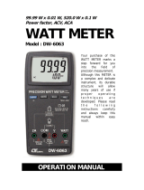
3 PHASE
POWER ANALYZER
Model : DW-6093
Y
our purchase o
f
this 3 PHASE
POWER ANALYZER
marks a step
forward for you into
the field o
f
precision
measurement.
A
lthough this
POWER ANALYZER
is a complex and
delicate instrument,
its durable structure
will allow many
years of use i
f
proper operating
techniques are
developed. Please
read the following
instructions
carefully and always
keep this manual
within easy reach.
OPERATION MANUAL

Caution Symbol
Caution :
* Risk of electric shock !
* During the measurement,
do not open the cabinet.
Caution :
* Do not apply the overload
voltage, current to the input
terminal !
* Remove test leads before open
the battery cover !
* Cleaning - Only use the dry
cloth to clean the plastic case !
Environment Conditions
* Installation Categories III 600V.
* Pollution Degree 2.
* Altitude up to 2000 meters.
* Indoor use.
* Relative humidity 80% max.

TABLE OF CONTENTS
1. FEATURES................................................................
.
1
2. SPECIFICATIONS...................................................... 2
2-1 General Specifications......................................... 2
2-2 Electrical Specifications....................................... 4
3. FRONT PANEL DESCRIPTION..................................... 8
4. MEASURING PREPARATION ......................................
.
10
4-1 The original screen.............................................. 10
4-2 Entry the measurement Screen............................
.
10
4-3 The summary description of keyboard...................12
4-4 SETUP KEY description.........................................13
4-5 Setting function description before measuring.......
.
14
5. MEASURING PROCEDURES .......................................
.
38
5-1 1Φ 2W ( one phase by two wires )
measurement.....................................................
.
38
5-2 1Φ 3W ( one phase by three wires )
measurement.....................................................
.
39
5-3 3Φ 3W ( three phase by three wires )
measurement.....................................................
.
41
5-4 3Φ 4W ( three phase by four wires )
measurement.....................................................
.
42
5-5 The CT and PT measurement............................... 44
5-6 ZERO adjustment for Watt Hour........................... 45
5-7 Data Logger function...........................................
.
46
5-8 Data Hold function............................................ 48
5-9 Backlight key.......................................................49
5-10 A ( Current ) Range key.....................................
.
49
5-11 LOWBAT screen.................................................50
5-12 Appendix 1........................................................51
6. MAINTENANCE..........................................................52
6-1 Cleaning.............................................................
.
52
6-2 Replacement of batteries ....................................
.
52
7. RS232 PC SERIAL INTERFACE.................................... 53
8. Download the saving data from the SD card to
the computer ( EXCEL software ) ...............................55
9. PATENT.................................................................... 59
10. THE ADDRESS OF AFTER SERVICE CENTER ............. 60

1. FEATURES
* Analysis for 3 phase multi-power system, 1P/2W,
1P/3W, 3P/3W, 3P/4W
* Voltage & Current are the True RMS value.
* True Power ( KW、MW、GW ) measurement.
* Apparent Power ( KVA、MVA、GVA ) measurement.
* Reactive Power ( KVAR MVAR、GVAR) measurement.
* Watt-Hour ( WH、SH、QH、PFH ).
* Power Factor( PF )、Phase Angle( Φ ).
* Voltage measurement range : 10 to 600 ACV
* Current probe input signal volage ( ACV ) :
200 mV/300 mV/500 mV/1 V/2 V/3 V.
Current probe input current range ( ACA ) :
20 A/200 A/2000 A ( 1200 A )/30 A/300A /3000 A.
* Meter can cooperate the universal current probe.
* Programmable CT ratio (1 to 600) and PT ratio (1 to 1000).
* ACV input impedance is 10 Mega ohms.
* Safety Standard : IEC 1010, CAT III 600V
* Built-in clock and Calendar, real time data record with
SD memory card , sampling time set from 2 to 7200
seconds. Just slot in the SD card into the computer, it
can down load the all the measured value with the
time information ( year/month/data/
hour/minute/second ) to the Excel directly, then user
can make the further data analysis by themselves.
* Complete set with 4 PCs Test Leads, 4 PCs Alligator
clips, 3 PCs Clamp Probe ( CP-1201 ), AC to DC 9V
adapter, 2 G SD memory card and Carrying bag.
* Computer data output, can cooperate with USB Cable
/USB-01 RS232 cable/UPCB-02 and Data Acquisition
software, SW-U811-WIN.
1

2. SPECIFICATIONS
2-1 General Specifications:
Circuit Custom one-chip of microprocessor LSI
circuit
Display * LCD Size :
81.4 X 61 mm ( 3.2 X 2.4 inch )
* Dot Matrix LCD (320 X 240 pixels )
with back light.
Measurement * ACV
* ACA
* AC WATT ( True Power )
AC WATT( Apparent Power )
AC WATT( Reactive Power )
* Power factor
* Phase angle
* Frequency
Wire 1P/2W, 1P/3W, 3P/3W, 3P/4W.
connections
Voltage ranges 10 ACV to 600 ACV, auto range.
Current probe * Current probe input signal volage ( ACV ) :
input signal
200mV/300mV/500mV/1V/2V/3V.
and range * Current probe input current range ( ACA ) :
20 A/200A/2000A (1200 A)/30A/300A/3000A
* Meter can cooperate the universal current probe.
Safety IEC1010 CAT III 600 V.
standard
ACV input 10 Mega ohms.
impedance
Range select ACV Auto range.
ACA Manual range.
Clamp 40 Hz to 1 KHz.
frequency
response
Spec. tested 45 to 65 Hz.
frequency
2

Over load ACV 720 ACV rms
protection ACA 1300 ACA with clamp probe
* For the Clamp ,CP-1201
Over Indicator * LCD display show " OL ".
* The data save into the SD card will show
" 9999 " or " 999 "
( overleap the decimal point ).
Under Indicator * LCD display show " UR ".
* The data save into the SD card will show
" 9999 " or " 999 "
( overleap the decimal point ).
Data Hold Freeze the display reading.
Data Record SD Card Record.
Sampling Time Approx. 1 second.
Power ON/OFF Manual OFF by push button.
Real time * Real time data logger, saved the data
data logger into SD memory card and down load
the all the measured value with the
time information ( year/month/data/
hour/minute/second ) down load
to the Excel
* Integration time for data logger :
2 seconds to 7200 seconds, the during
of setting step are 2 seconds.
Data Output RS232 computer serial interface :
USB/RS232 * Connect the optional USB cable
* Computer
USB-01 will get the USB plug.
interface
* Connect the optional RS232 cable
UPCB-02 will get the RS232
plug.
Operating 0 to 50 ( 32 to 122 ).℃℉
Temperature
Operating Less than 80% R.H..
Humidity
Power Supply * DC 1.5V, AA ( UM-3 ) Battery X 8 PCs
(Alkaline or heavy-duty battery).
* AC to DC 9V power adapter.
3

Power * Meter : 250 DCmA.
Consumption * Clamp : 22 DCmA.
Clamp max. 50 mm ( 2.0 inch ) Dia.
conductor Size
* For the Clamp ,CP-1201
Weight * Meter : 975g ( includes batteries )
* Clamp ( includded cable ) : 500g
Dimension
Meter :
225 X 125 X 64 mm
( 8.86 X 4.92 X 2.52 inch )
Clamp :
210 X 64 X 33mm
( 8.3 X 2.5 X 1.3 inch )
Clamp Jaw : 86 mm (3.4 inch)- outside
Accessories * Instruction manual..............
.
1 PC
Included *
T
est Leads (TL88-4AT)........
.
1 Set (4 PCs)
* Alligator clips (TL88-4AC) 1 Set (4 PCs)
* Clamp Probe ( CP-1201 ).....
.
3 PCs
*
A
C to DC 9V adapter...........
.
1 PC
* SD card ( 2 G )...................
.
1 PC
* Carrying bag....................... 1 PC
Optional * 2000 Amp current probe, CP-2000
Accessories * 200 Amp current probe, CP-200
* Flexible 3000 Amp current probe, CP-3000
* USB Cable , USB-01
* RS232 cable, UPCB-02
* Data Acquisition software, SW-U811
* EXCEL Data Acquisition software, SW-E802
2-2 Electrical Specifications:
ACV
Range Resolution Accuracy
10.0V to 600.0V 0.1V ± (0.5%+0.5V)
* Phase to neutral line
10.0V to 600.0V
* Phase to phase
4

ACA
Range Resolution Accuracy
20A 0.001A,
< 10 A
± (0.5%+0.1A)
0.01A,
10 A≧
200A 0.01A,
< 100 A
± (0.5%+0.5A)
0.1A,
100 A≧
1200A 0.1A,
< 1000 A
± (0.5%+5A)
1A,
1000 A≧
Power factor
Range Resolution Accuracy
0.00 to 1.00 0.01 ± 0.04
Remark :
* PFH : Long term power factor
* PFΣ :
For 3Φ 4W, 3Φ 3W
PFΣ = ( PF1 + PF2 + PF3 )/3
For 1Φ 3W
PFΣ = ( PF1 + PF2 )/2
Φ ( Phase angle )
Range Resolution Accuracy
-180° to 180° 0.1° ± 1°
* ACOS ( PF )
Frequency
Range Resolution Accuracy
45 to 65 Hz 0.1 Hz 0.1 Hz
5

Active (Real) Power
Range Resolution Accuracy
0.000 to 9.999 KW *0.001/0.01/0.1 KW ± (1%+0.008KW)
10.00 to 99.99 KW *0.01/0.1 KW ± (1%+0.08KW)
100.0 to 999.9 KW 0.1 KW ±(1%+0.8KW)
1.000 to 9.999 MW 0.001 MW ± (1%+0.008MW)
* : The resolution is changed according the different ACA range.
Apparent Power
Range Resolution Accuracy
0.000 to 9.999 KVA *0.001/0.01/0.1KVA ± (1%+0.008KVA)
10.00 to 99.99 KVA *0.01/0.1 KVA ± (1%+0.08KVA)
100.0 to 999.9 KVA 0.1 KVA ±(1%+0.8KVA)
1.000 to 9.999 MVA 0.001 MVA ± (1%+0.008MVA)
* : The resolution is changed according the different ACA range.
Reactive Power
Range Resolution Accuracy
0.000 to 9.999 KVAR *0.001/0.01/0.1KVAR ± (1%+0.008 KVAR)
10.00 to 99.99 KVAR *0.01/0.1 KVAR ± (1%+0.08 KVAR)
100.0 to 999.9 KVAR 0.1 KVAR ± (1%+0.8 KVAR)
1.000 to 9.999 MVAR 0.001 MVAR ± (1%+0.008 MVAR)
* : The resolution is changed according the different ACA range.
6

Watt Hour ( Active Power Hour) : WH
Range Resolution Accuracy
0.000 to 9.999 KWH 0.001 KWH ± (2%+0.008 KWH)
10.00 to 99.99 KWH 0.01 KWH ± (2%+0.08 KWH)
100.0 to 999.9 KWH 0.1 KWH ±(2%+0.8 KWH)
1.000 to 9.999 MWH 0.001 MWH ± (2%+0.008 MWH)
VA Hour ( Apparent Power Hour ) : SH
Range Resolution Accuracy
0.000 to 9.999 KVAH 0.001 KVAH ± (2%+0.008 KVAH)
10.00 to 99.99 KVAH 0.01 KVAH ± (2%+0.08 KVAH)
100.0 to 999.9 KVAH 0.1 KVAH ± (2%+0.8 KVAH)
1.000 to 9.999 MVAH 0.001 MVAH ± (2%+0.008 MVAH)
VAR Hour ( Reactive Power Hour ) : QH
Range Resolution Accuracy
0.000 to 9.999 KVARH 0.001 KVARH ± (2%+0.008 KVARH)
10.00 to 99.99 KVARH 0.01 KVARH ± (2%+0.08 KVARH)
100.0 to 999.9 KVARH 0.1 KVARH ±(2%+0.8 KVARH)
1.000 to 9.999 MVARH 0.001 MVARH ± (2%+0.008 MVARH)
7

3. FRONT PANEL DESCRIPTION
Fig. 1
8

3-1 Display
3-2 1Φ 3Φ ( Phase/wire ) key button
3-3 key button▲
3-4 key button▼
3-5 Hold key button
3-6 Backlight key button
3-7 Power key button
3-8 Exit key button
3-9 REC key button
3-10 A ( current ) range key button
3-11 Shift key button
3-12 Setup key button
3-13 Voltage input terminals
3-14A Current probe signal input sockets
3-14B Current probe power sockets
3-15 SD card socket
3-16 RS232 socket
3-17 Reset button
3-18 DC 9V power adapter socket
3-19 Battery Cover/Battery compartment
3-20 Stand
3-21 Current Sense Jaw
3-22 Trigger
3-23A Current probe signal plugs
3-23B Current probe power plug
9

4. MEASURING PREPARATION
4-1 The original screen
4-2 Entry the measurement Screen
1)The bottom right display of screen 1 will show as " SD
Check " along with blinking while inserting SD CARD
then disappears after several seconds that indicates the
data from SD CARD has been read completed.
2)The bottom right display of screen 2 will show as " NO
DISK " along with blinking when SD CARD is not
inserted.
10

screen 1 ( 4-2 )
V12: 0.0 V V1: 0.0 V A1: 0.00 A
V23: 0.0 V V2: 0.0 V A2: 0.00 A
V31: 0.0 V V3: 0.0 V A3: 0.00 A
P1: -0.000 KW S1: 0.000KVA Q1: -0.000 KVAR
P2: -0.000 KW S2: 0.000KVA Q2: -0.000 KVAR
P3: -0.000 KW S3: 0.000KVA Q3: -0.000 KVAR
PΣ : -0.000 KW SΣ : 0.000KVA QΣ :-0.000 KVAR
PF1: -0.00 PF 2: -0.00 PF 3: -0.00
PFΣ : 0.00 PF H: 0.00
Φ 1: - 0.0° Φ 2: - 0.0° Φ 3: - 0.0°
WH: 0.000 KWH SH: 0.000KVAH
QH: 0.000 KVARH FREQ: 0.0 Hz
CP1201 SD
20A 3Φ 4W SEC: 2 CT: 1 PT: 1 Check
screen 1 ( 4-2 )
V12: 0.0 V V1: 0.0 V A1: 0.00 A
V23: 0.0 V V2: 0.0 V A2: 0.00 A
V31: 0.0 V V3: 0.0 V A3: 0.00 A
P1: -0.000 KW S1: 0.000KVA Q1: -0.000 KVAR
P2: -0.000 KW S2: 0.000KVA Q2: -0.000 KVAR
P3: -0.000 KW S3: 0.000KVA Q3: -0.000 KVAR
PΣ : -0.000 KW SΣ : 0.000KVA QΣ :-0.000 KVAR
PF1: -0.00 PF 2: -0.00 PF 3: -0.00
PFΣ : 0.00 PF H: 0.00
Φ 1: - 0.0° Φ 2: - 0.0° Φ 3: - 0.0°
WH: 0.000 KWH SH: 0.000KVAH
QH: 0.000 KVARH FREQ: 0.0 Hz
CP1201 NO
20A 3Φ 4W SEC: 2 CT: 1 PT: 1 DISK
11

4-3 The summary description of keyboard
1)POWER KEY ( 3-7, Fig. 1 ) :
Press the key to turn the instrument ON/OFF.
2)1Φ 3Φ ( phase/wire ) KEY ( 3-2, Fig. 1 ) :
Press the key to select
(1P/2W、1P/3W、3P/3W、3P/4W) measurement
function mode.
3)A ( current ) RANGE KEY ( 3-10, Fig. 1 ) :
Press the key to change the current range quickly.
4)REC KEY ( 3-9, Fig. 1 ) :
The data record key for SD CARD.
5)HOLD KEY ( 3-5, Fig. 1 ) :
Press the key to freeze the display reading.
6)BACKLIGHT KEY ( 3-6, Fig. 1 ) :
Press the key to switch LCD backlight to ON/OFF.
7)SETUP KEY ( 3-12, Fig. 1 ) :
Press the key to setup the function before measuring.
8)EXIT KEY ( 3-8, Fig. 1 ) :
Press the key to exit setting screen.
9)SHIFT KEY ( 3-11, Fig. 1 )
Press the key to set the different functions in setting
screen.
10) UP ( ) KEY ( 3-3, Fig. 1 ) : ▲
Press the key to move the cursor up in setting
screen.
11) DOWN ( ) KEY ( 3-4, Fig. 1 ) :▼
Press the key to move the cursor down in setting
screen.
12

4-4 SETUP KEY description:
4-4-1 SHIFT KEY
* SHIFT 1 : When the symbols " SETUP " and " SHIFT 1 "
are appeared on up right display of screen 1 in the
meantime, and then use the or to select the▲▼
expect item.
* SHIFT 2 : When the symbols " SETUP " and " SHIFT 2 "
are appeared on up right display of screen 2 in the
meantime, and then use the ▲ or ▼ to select ( 1P/2W、
1P/3W、3P/3W、3P/4W ) in File Name function.
Folder Name: WTA01 SETUP
F
il
e Name: 3P401001.XLS SHIFT 1
REC Date: 2008-11-28 00:03:17
Samp
l
in
g
Time: 2
De
l
et Fi
l
e: 0 % Decima
l
: Basic
SD Format: 0 % C
l
amp Type: CP1201
Use Size: 388 KB
A
Ran
g
e: 20
A
Free Size: 1946 MB V Ran
g
e: 200mV
Tota
l
Size: 1946 MB RS232 Out Se
l
:
PT: 1 : 1 V1 I1 P1
CT: 1 : 1 S1 Q1 PF1
Beep: ON
Φ
1 WH FREQ
Y
ear Mont
h
Date Hour Minute Secon
d
2010 11 13 14 37 25
Folder Name: WTA01 SETUP
F
il
e Name: 3P401001.XLS SHIFT 2
REC Date: 2008-11-28 00:03:17
Samp
l
in
g
Time: 2
De
l
et Fi
l
e: 0 % Decima
l
: Basic
SD Format: 0 % C
l
amp Type: CP1201 screen
2
(
4
-
4
)
Use Size: 388 KB
A
Ran
g
e: 20
A
Free Size: 1946 MB V Ran
g
e: 200mV
Tota
l
Size: 1946 MB RS232 Out Se
l
:
PT: 1 : 1 V1 I1 P1
CT: 1 : 1 S1 Q1 PF1
Beep: ON
Φ1 WH FREQ
Y
ear Mont
h
Date Hour Minute Secon
d
2010 11 13 14 37 25
13

4-4-2 The Setting Function menu
* Folder Name : Set the expect folder name for SD CARD,
the range is between WTA01 and WTA10.
* File Name: Set the file name for SD CARD, It allows setting
50 filenames in this function.
* REC Date: Show the recorded time of existing files
( Year/Month/Date, Hour/Min./Sec. )
* Sampling Time : Set the sampling time from 2 to 7200 seconds.
* Delete File : To delete the existing data from SD CARD.
* SD Format : to Format SD CARD fast.
* PT : Set the potential transformer from 1 to 1000.
* CT : Set the current transformer from 1 to 600.
* Beep : Set to ON/OFF for buzzer.
* Clamp Type : Select the Clamp Type to CP-1201, CP-200
CP-2000, CP-3000 or Other Type.
* RS232 out Sel. : Set RS232 output function, maximum up
to nine items can be selected to output. screen 1 screen 2.
* Year : Set the year.
* Month : Set the month.
* Date : Set the date.
* Hour : Set the hour.
* Minute : Set the minute.
* Second : Set the second.
4-5 Setting function description before measuring
Press SETUP KEY to enter setting function screen, the
selected item will be displayed in highlight.
14

4-5-1 Folder Name: Set the folder name for SD
screen 1 ( 4-5-1 )
Folder Name: WTA01 SETUP
File Name: 3P401001.XLS
REC Date: 2008-11-28 00:03:17
Sampling Time: 2
Delet File: 0 % Decimal: Basic
SD Format: 0 % Clamp Type: CP1201
Use Size: 388 KB A Range: 20A
Free Size: 1946 MB V Range: 200mV
Total Size: 1946 MB RS232 Out Sel:
PT: 1 : 1 V1 I1 P1
CT: 1 : 1 S1 Q1 PF1
Beep: ON Φ1 WH FREQ
Year Month Date Hour Minute Second
2010 12 05 11 14 49
screen 2 ( 4-5-1 )
Folder Name: WTA01 SETUP
File Name: 3P401001.XLS SHIFT 1
REC Date: 2008-11-28 00:03:17
Sampling Time: 2
Delet File: 0 % Decimal: Basic
SD Format: 0 % Clamp Type: CP1201
Use Size: 388 KB A Range: 20A
Free Size: 1946 MB V Range: 200mV
Total Size: 1946 MB RS232 Out Sel:
PT: 1 : 1 V1 I1 P1
CT: 1 : 1 S1 Q1 PF1
Beep: ON Φ1 WH FREQ
Year Month Date Hour Minute Second
2010 12 05 11 14 34
15

A : Folder Name range: WTA01 to WTA10.
B : Press or to select the expect folder number, the▲▼
number consists of " 01 to 10 " (as screen 1).
C : Press or continuously at least two seconds can▲▼
skip the numbers faster.
D : Press SHIFT KEY once, the symbol " SHIFT1" will
appear on up right display, and then press to entry next▼
setting function as screen 2 (Folder Name File Name).→
4-5-2 File Name: Set the file name for SD
A : The screen will show " NO File " indicator in REC Date
option when the selected file is new ( as screen 1 ).
B : The screen will show recording date and time in REC
Date option when the selected file has been recorded
as screen 2.
screen 1 ( 4-5-2 )
Folder Name: WTA03 SETUP
File Name: 3P401001.XLS
REC Date: NO File
Sampling Time: 2
Delet File: 0 % Decimal: Basic
SD Format: 0 % Clamp Type: CP1201
Use Size: 388 KB A Range: 20A
Free Size: 1946 MB V Range: 200mV
Total Size: 1946 MB RS232 Out Sel:
PT: 1 : 1 V1 I1 P1
CT: 1 : 1 S1 Q1 PF1
Beep: ON Φ1 WH FREQ
Year Month Date Hour Minute Second
2010 11 13 14 37 25
16

screen 2 ( 4-5-2 )
Folder Name: WTA01 SETUP
File Name: 3P401001.XLS
REC Date: 2008-11-28 00:03:17
Sampling Time: 2
Delet File: 0 % Decimal: Basic
SD Format: 0 % Clamp Type: CP1201
Use Size: 388 KB A Range: 20A
Free Size: 1946 MB V Range: 200mV
Total Size: 1946 MB RS232 Out Sel:
PT: 1 : 1 V1 I1 P1
CT: 1 : 1 S1 Q1 PF1
Beep: ON Φ1 WH FREQ
Year Month Date Hour Minute Second
2010 12 05 11 15 31
C : File Name description : press or in screen 2 to▲▼
select expect file number from 001 to 050.
Remark : When press or > 2 sec, the setting ▲▼
no. will change fast.
* 1P201001 : 1P2 means one phase by two wires, 01
means folder number, 001 means file number.
* 1P301001: 1P3 means one phase by three wires,
01 means folder number, 001 means file number.
* 3P301001 : 3P3 means three phases by three wires,
01 means folder number, 001 means file number.
* 3P401001 : 3P4 means three phases by four
wires, 01 means folder number, 001 means file
number.
D : The up right display will show " SHIFT1 " symbol
while pressing SHIFT KEY once in screen 2, and then
press to enter next setting function as screen 3▼
( File Name Sampling Time ).→
17
/