Astria Fireplaces WRT/WCT40CR/CL Instruction Sheet
- Category
- Rack accessories
- Type
- Instruction Sheet

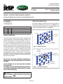
Figure 1 - Masonry Fireplaces
Figure 2 - Factory Built Fireplaces
PURFIRE™ ADJUSTABLE EMISSION CONTROL HOOD KITS
[FOR USE WITH MASONRY AND FACTORY BUILT WOOD-BURNING FIREPLACES]
PURFIRE™ ADJUSTABLE EMISSION
CONTROL HOOD KITS
P/N 127124-01
Rev. B, 04/2017
HEARTH PRODUCTS
KITS AND ACCESSORIES
KIT CONTENTS
1 ea. Adjustable Hood
4 ea. Mounting Screws
1 ea. Instruction Sheet
PureFire™ Aftermarket Adjustable Emission Control Hood Kits
Cat. No. Model Description
F0878 AH1924 Adjusts to fi replace back wall measuring 19"-24"
F0879 AH2231 Adjusts to fi replace back wall measuring 22"-31"
F0880 AH3143 Adjusts to fi replace back wall measuring 31"-43"
GENERAL INFORMATION
The PureFire Catalytic Hood can be installed in a wood burning
masonry fi replace or a factory built zero clearance fi replace. The
PureFire Catalytic Hood can easily be installed in less than an
hour. Four mounting screws will hold the two mounting brack-
ets in place. Included with the hood are two sets of mounting
brackets (for masonry fi replace or factory-built fi replace). The
PureFire Catalytic Hood has a trapezoidal shape to fi t the angu-
lar sides of the fi rebox. The hood is equipped with adjustable
extensions that slide in and out. The PureFire Catalytic Hood
should be installed after the fi replace is completely fi nished. It
is designed to be installed as an add-on device. It is mounted on
two brackets that are mechanically attached to the side walls of
the fi rebox. Ensure that the fi rebox is structurally sound before
beginning the installation.
READ ALL THE STEPS BEFORE STARTING THE CONVERSION. IN-
STALLER NOTICE: THESE INSTRUCTIONS MUST BE LEFT WITH THE
APPLIANCE.
THE APPLIANCE MUST BE OFF AND COLD BEFORE PERFORMING
THE INSTALLATION.
ALL WARNINGS, PRECAUTIONS AND INSTRUCTIONS IN THE INSTAL-
LATION AND OPERATION MANUAL PROVIDED WITH THE APPLIANCE
APPLY TO THESE INSTRUCTIONS.
INSTALLATION INSTRUCTIONS
For Masonry fi replace application, the retainer brackets are
attached to the fi rebrick on the side walls (see Figure 1). For
factory-built fi replace application, the retaining bracket rest or
is above the top edge of fi rebrick (see Figure 2).
WARNING: STOP: Before installation of this prod-
uct your chimney must be cleaned by a professional
chimney sweep.
1
IHP.us.com
Self-Drilling
Sheet Metal Screw
Top Edge
of Firebrick
End Tab
Masonry
Screw
Left Hand
Side Shown
End Tab
Left Hand
Side Shown

IHP.us.com
2
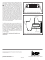
Figure 3 - PureFire Catalytic Hood Installed (Top View)
Figure 4 - PureFire Catalytic Hood Installed (Side View)
The height of the bracket installation is determined by the fi re-
place opening. The brackets should be installed so they are
even or above the height of the fi replace opening (lintel) or the
smoke shelf. The brackets can be used to identify the location
of the mounting screw holes. A black felt tip should be used
to identify the location for drilling. Two holes will need to be
drilled on each side of the fi rebox. For masonry application, the
brackets are attached using masonry screws (provided). For
factory-built fi replace application, brackets are attached using
self-drilling sheet metal screws (provided). Make sure that the
brackets are installed as shown. The bracket end tab should be
facing the front of the fi rebox. The end tab will prevent the hood
from moving. After the brackets are installed, the hood should
be adjusted to the correct dimension to properly fi t into the
brackets. Measure the distance between the installed brackets
on both front and back. Move the adjustable extensions on the
hood until the front and back on the hood extensions equal the
dimensions of the mounting brackets. Tighten the retention
screws on each side of the hood.
The PureFire Catalytic Hood can now be installed in the fi re-
box. Position the hood in the brackets so that it is securely in
place. The PureFire Catalytic Hood should be located against
the back wall of the fi rebox directly above the grate (see Figure
3). Minimum Distance between the leading edge of the smoke
shelf and the hood is 6" (see Figure 4). The damper Handle
(if required) should pass between the combustor blocks and
remain operational. Chain operated units will have the chain
in front of the hood.
The HearthCAT™ emission control system is now
ready for use.
Hearth Cat Hood
6"
Minimum
Smoke
Shelf
Damper Blade
Printed in U.S.A. © 2014 Innovative Hearth Products
P/N 127124-01 Rev. B 04/2017
IHP reserves the right to make changes at any time, without notice, in design, materials, specifi ca-
tions, prices and also to discontinue colors, styles and products. Consult your local distributor
for fi replace code information.
1508 Elm Hill Pike, Suite 108 • Nashville, TN 37210
-
 1
1
-
 2
2


Astria Fireplaces WRT/WCT40CR/CL Instruction Sheet
- Category
- Rack accessories
- Type
- Instruction Sheet
Ask a question and I''ll find the answer in the document
Finding information in a document is now easier with AI
Related papers
Other documents
-
FMI AH3143P Operating instructions
-
-
-
-
-
Superior Fireplaces WRE6000 Operating instructions
-
Superior WRT4842RS Installation And Operation Instructions Manual
-
-
-