Astria Fireplaces Devonshire Installation guide
- Category
- Fireplaces
- Type
- Installation guide
This manual is also suitable for

Save this manual for future reference
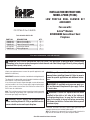
INSTALLATION INSTRUCTIONS
MODEL LPDBK (F1084)
LOW PROFILE DUAL BLOWER KIT
ACCESSORY
For use with:
Astria™ Models:
DEVONSHIRE Series Direct Vent
Fireplace
P127164-01
P/N 127164-01 Rev. C 06/2015
For more information, visit IHP.US.com
WARNING: ELECTRICAL GROUNDING INSTRUCTIONS This appliance is equipped with a three-prong
(grounding) plug for your protection against shock hazard and should be plugged directly into a properly
grounded three-prong receptacle.
(Check your appliance owner's manual for specific applications and
additional instructions.)
IMPORTANT: Read entire instruction sheet before installing blower kit.
This blower kit is approved for use with models listed above. Do not
use blower kit in any other fireplace models.
If any of these parts are missing or damaged, contact dealer where
you purchased this kit. If they cannot supply original replacement
parts, either contact your nearest Parts Central or contact IHP at
IHP.US.com for information.
Note: This installation requires the gas supply line to be disconnected
before removing log assembly. Call a qualified service person to
disconnect gas supply from fireplace.
WARNING: Turn off, unplug, and let fireplace cool
before installing blower kit. Only a qualified service
person should service and repair fireplace.
PART NO. DESCRIPTION QTY.
126466-01 Blower Assembly L. 1
126466-02 Blower Assembly R. 1
126468-01 Speed Control Assembly 1
127164-01 Instruction Sheet 1
126972-01 Wiring Diagram 1
Parts included with this kit:
NOTICE: Log set/burner and hearth refractories, must be
removed before installing blower kit. Refer to owner's
manual for specific applications and additional instruc-
tions.
WARNING: A qualified service person must con-
nect and disconnect fireplace with gas supply. Follow
all local codes.
WARNING: If there is a duplex electrical outlet
installed in the right or left side of the bottom of
the fireplace base area, be sure that the electrical
power to the outlet is turned off before proceeding
with blower installation. Failure to do this may result
in serious injury.
The blower kit utilizes two rotary squirrel cage type blower with
magnetic attachment and variable speed control.
Note: This blower kit is approved for use with models listed on this
page. Do not use blower kit in any other fireplace models.

IHP.US.com 127164-01C2
ACCESSING FIREPLACE
Figure 4 - Removing/Installing Burner Base
Log Assembly
Firebox Bottom
Burner Base
Screws
Spacers
Figure 3 - Removing Loose Logs 36'' Models Only
Loose Log #3
Loose Log #2
Loose Log #1
Underneath Log #2
CAUTION: Wear gloves and safety glasses while
handling or removing parts from your firebox. Some
metal edges may be sharp. Use caution with log sets
as logs are fragile.
1. Remove barrier by Holding the barrier in front of the glass
door and slide it up into the channel underneath the upper
front face and out of the slots on the bottom front face (see
Figure 1).
2. Remove access door by pulling it towards you.
3. Remove glass door by unlocking 2 door latches on bottom of
firebox (see Figure 2).
4. Tilt open glass door 45° from the bottom of firebox and lift up
to release door from firebox top retainer (see Figure 2).
5. Remove grate from slots in burner.
6. For 36" models only, remove 3 loose logs, log set and burner
base as shown in Figure 3.
7. For 42" models only, remove log set and burner base.
8. Carefully lift and remove 3 hearth refractories from fireplace.
NOTE: Rear and side refractories do not need to be removed.
9. Remove 3 spacers and one back flange from firebox bottom
by removing 13 screws from front, sides and back of firebox
burner base to disengage from firebox bottom. Lift up entire
base from unit (see Figure 4).
10. Reverse all the steps in order to reinstall removed items.
Figure 1 - Removing and Replacing Barrier
Channel
Barrier
Frame
Slot
Figure 2 - Removing/Replacing Glass Door and Access Door
Door
Retainer
Location
Glass
Door
Bottom
Access Panel
Door
Latches
Location
WARNING: Reinstall any barrier removed before
operating the fireplace. The barrier is designed to
reduce the risk of burns from hot glass. Do not operate
the fireplace without the barrier installed.

IHP.US.com 127164-01C 3
Note: The LPDBK blower kit, is for application into direct-vent models
listed on the front page only and is already factory pre-wired. When
installing the LPDBK blower kit, you must first check that all wiring
connections are secure from the speed control to the blower.
Make
sure gasket material adhered to the bottom casing of blower is intact
(See Figure 5).
1. For 36'' models only, place the blowers thru the opening of the
burner base already removed and against the rear wall of the
firebox outer wrapper with the exhaust ports directed upward
(see Figures 6 and 7).
2. For 42'' models only, the blowers have to be installed against
the rear wall and towards the sides making sure that the air ports
are not blocked by the firebox rear plenum (see Figures 6 and 8).
3. Be certain that all the terminals are securely attached to terminals
on blower and that the screws retaining the green ground wires
are tight (See Figure 5).
4. Mount speed control box by placing it in the front lower corner,
where it can be easily accessed. We recommend the front right
side of the fireplace bottom (See Figure 8).
5. Install the optional remote control kit (WRC) if desired, this
remote control kit is for turning on/off the blower kit only. The
speed has to be set manually before using the remote control.
Follow the instructions included with this kit.
6. Reinstall log set/burner module. If needed, replace burner gasket
before reinstalling log set/burner module.
NOTE: Use two hands to place burner base/logs.
7. Reinstall 3 spacers and the rear flange to bottom firebox (see
Figure 4).
8. Reinstall 3 hearth refractories
9. Reinstall grate, glass door, access door, and barrier.
BLOWER INSTALLATION
Figure 5 - Blower Model LPDBK
Magnet
Magnet
Exhaust Port
Ring Connectors
Spade
Connectors
White Wires
Black
Wires
Speed
Control
Ground
Wires
Wire Nut
Connectors
Power Cord
Air Flow
Direction
Figure 6 - Installing Blower Kit
Figure 8 - Blower Kit and Speed Control Location 42'' Models
only
Figure 7 - Blower Kit and Speed Control Location 36'' Models
only
Note: Refractory
Panels and Wires not
shown for clarity
Rear
rebox
Plenum
Location
Speed Control
Note: Refractory
Panels and Wires not
shown for clarity
Speed Control
Gasket
(Top &
Bottom)
Gasket
(Top &
Bottom)

CAUTION: Never touch the blower wheel while in
operation.
1. Check to make sure that the power cord is completely clear of
the blower wheel and that there are no other foreign objects in
blower wheel. Also double check all wire leads and make sure
wire routing is not pinched or in a precarious position. Correct
accordingly.
2. Turn on power to duplex outlet if previously turn off per the
warning on page 1.
3. Plug in blower power cord to duplex outlet.
4. Turn blower on and check for operation. Turn blower off by turn-
ing knob fully counterclockwise before continuing.
5. The blower will only run when the speed control knob is in the
ON position. The blower speed can be adjusted by rotating the
control knob. To turn off, turn knob fully counterclockwise until
it clicks off.
6. Peel off the backing paper and stick the supplied wiring diagram
decal on the left fireplace bottom approximately 1.5'' in front of
the fireplace lower face (see Figure 9).
7. Replace all panels and/or accessories if previously removed.
CONNECTING POWER AND OPERATING BLOWER
Figure 9: Location of Wiring Diagram Decal
Variable
Fan Switch
WhiteWhite
Black
Green
On
110/115
V.A.C.
Blower
Motor
Black
Black
Black
Off
Blower
Motor
120 Vac.
60 Hz.
.37 Amps
Figure 10: Wiring Diagram
REPLACEMENT PARTS
Note: Use only original replacement parts. This will protect your
warranty coverage for parts replaced under warranty.
Normally, all parts should be ordered through your IHP distributor
or dealer. Parts will be shipped at prevailing prices at time of order.
When ordering repair parts, always give the following information:
1. The model number of the fireplace.
2. The serial number of the fireplace.
3. The part number.
4. The description of the part.
5. The quantity required.
6. The installation date of the fireplace.
TECHNICAL SERVICE
You may have further questions about installation, operation, or
troubleshooting. Please contact your IHP dealer for any questions
or concerns. When contacting your dealer please have your model
and serial numbers of your fireplace ready. You can also visit our
web site at IHP.US.com.
ACCESSORIES
Purchase this accessory thru your IHP distributor or dealer..
F1080 - WRC Standard electronic ON/OFF remote control kit.
Innovative Hearth Products reserves the right to make changes at any time, without
notice, in design, materials, specifications, prices and also to discontinue colors, styles
and products. Consult your local distributor for fireplace code information.
Printed in U.S.A. © 2014 IHP LLC
P/N 127164-01 Rev. C 06/2015.
P127164-01
Wiring Diagram Decal
approximately 1.5'' in
front of the replace
lower face
1508 Elm Hill Pike, Suite 108 • Nashville, TN 37210
-
 1
1
-
 2
2
-
 3
3
-
 4
4


Astria Fireplaces Devonshire Installation guide
- Category
- Fireplaces
- Type
- Installation guide
- This manual is also suitable for
Ask a question and I''ll find the answer in the document
Finding information in a document is now easier with AI
Related papers
-
Astria Fireplaces VR(C)T43 Instruction Sheet
-
-
-
-
-
-
-
-
-
Other documents
-
FMI LPDBK Operating instructions
-
Superior Fireplaces DRL3500 Operating instructions
-
-
-
-
Superior VRT2500 Operating instructions
-
-
-
-