Page is loading ...

Motherboard
PRIME Z270M-PLUS

ii
E11993
First Edition
August 2016
Copyright © 2016 ASUSTeK COMPUTER INC. All Rights Reserved.
No part of this manual, including the products and software described in it, may be reproduced,
transmitted, transcribed, stored in a retrieval system, or translated into any language in any form or by any
means, except documentation kept by the purchaser for backup purposes, without the express written
permission of ASUSTeK COMPUTER INC. (“ASUS”).
Product warranty or service will not be extended if: (1) the product is repaired, modied or altered, unless
such repair, modication of alteration is authorized in writing by ASUS; or (2) the serial number of the
product is defaced or missing.
ASUS PROVIDES THIS MANUAL “AS IS” WITHOUT WARRANTY OF ANY KIND, EITHER EXPRESS
OR IMPLIED, INCLUDING BUT NOT LIMITED TO THE IMPLIED WARRANTIES OR CONDITIONS OF
MERCHANTABILITY OR FITNESS FOR A PARTICULAR PURPOSE. IN NO EVENT SHALL ASUS, ITS
DIRECTORS, OFFICERS, EMPLOYEES OR AGENTS BE LIABLE FOR ANY INDIRECT, SPECIAL,
INCIDENTAL, OR CONSEQUENTIAL DAMAGES (INCLUDING DAMAGES FOR LOSS OF PROFITS,
LOSS OF BUSINESS, LOSS OF USE OR DATA, INTERRUPTION OF BUSINESS AND THE LIKE),
EVEN IF ASUS HAS BEEN ADVISED OF THE POSSIBILITY OF SUCH DAMAGES ARISING FROM ANY
DEFECT OR ERROR IN THIS MANUAL OR PRODUCT.
SPECIFICATIONS AND INFORMATION CONTAINED IN THIS MANUAL ARE FURNISHED FOR
INFORMATIONAL USE ONLY, AND ARE SUBJECT TO CHANGE AT ANY TIME WITHOUT NOTICE,
AND SHOULD NOT BE CONSTRUED AS A COMMITMENT BY ASUS. ASUS ASSUMES NO
RESPONSIBILITY OR LIABILITY FOR ANY ERRORS OR INACCURACIES THAT MAY APPEAR IN THIS
MANUAL, INCLUDING THE PRODUCTS AND SOFTWARE DESCRIBED IN IT.
Products and corporate names appearing in this manual may or may not be registered trademarks or
copyrights of their respective companies, and are used only for identication or explanation and to the
owners’ benet, without intent to infringe.
Offer to Provide Source Code of Certain Software
This product contains copyrighted software that is licensed under the General Public License (“GPL”),
under the Lesser General Public License Version (“LGPL”) and/or other Free Open Source Software
Licenses. Such software in this product is distributed without any warranty to the extent permitted by the
applicable law. Copies of these licenses are included in this product.
Where the applicable license entitles you to the source code of such software and/or other additional data,
you may obtain it for a period of three years after our last shipment of the product, either
(1) for free by downloading it from http://support.asus.com/download
or
(2) for the cost of reproduction and shipment, which is dependent on the preferred carrier and the location
where you want to have it shipped to, by sending a request to:
ASUSTeK Computer Inc.
Legal Compliance Dept.
15 Li Te Rd.,
Beitou, Taipei 112
Taiwan
In your request please provide the name, model number and version, as stated in the About Box of the
product for which you wish to obtain the corresponding source code and your contact details so that we
can coordinate the terms and cost of shipment with you.
The source code will be distributed WITHOUT ANY WARRANTY and licensed under the same license as
the corresponding binary/object code.
This offer is valid to anyone in receipt of this information.
ASUSTeK is eager to duly provide complete source code as required under various Free Open Source
Software licenses. If however you encounter any problems in obtaining the full corresponding source
code we would be much obliged if you give us a notication to the email address [email protected], stating
the product and describing the problem (please DO NOT send large attachments such as source code
archives, etc. to this email address).

iii
Contents
Safety information ...................................................................................... iv
About this guide ......................................................................................... iv
Package contents ....................................................................................... vi
PRIME Z270M-PLUS specications summary ......................................... vi
Chapter 1 Product introduction
1.1 Before you proceed ..................................................................... 1-1
1.2 Motherboard overview ................................................................. 1-1
1.3 Central Processing Unit (CPU) ................................................. 1-10
1.4 System memory ......................................................................... 1-11
1.5 Software support ........................................................................ 1-13
Chapter 2 BIOS information
2.1 Managing and updating your BIOS ............................................ 2-1
2.2 BIOS setup program .................................................................... 2-6
2.3 My Favorites ............................................................................... 2-16
2.4 Main menu .................................................................................. 2-18
2.5 Ai Tweaker menu ........................................................................ 2-20
2.6 Advanced menu ......................................................................... 2-30
2.7 Monitor menu ............................................................................. 2-39
2.8 Boot menu .................................................................................. 2-43
2.9 Tool menu ................................................................................... 2-48
2.10 Exit menu .................................................................................... 2-49
Appendix
Notices .......................................................................................................A-1
ASUS contact information .......................................................................A-5

iv
Safety information
Electrical safety
• To prevent electrical shock hazard, disconnect the power cable from the electrical outlet
before relocating the system.
• When adding or removing devices to or from the system, ensure that the power cables
for the devices are unplugged before the signal cables are connected. If possible,
disconnect all power cables from the existing system before you add a device.
• Before connecting or removing signal cables from the motherboard, ensure that all
power cables are unplugged.
• Seek professional assistance before using an adapter or extension cord. These devices
could interrupt the grounding circuit.
• Ensure that your power supply is set to the correct voltage in your area. If you are not
sure about the voltage of the electrical outlet you are using, contact your local power
company.
• If the power supply is broken, do not try to x it by yourself. Contact a qualied service
technician or your retailer.
Operation safety
• Before installing the motherboard and adding components, carefully read all the manuals
that came with the package.
• Before using the product, ensure all cables are correctly connected and the power
cables are not damaged. If you detect any damage, contact your dealer immediately.
• To avoid short circuits, keep paper clips, screws, and staples away from connectors,
slots, sockets and circuitry.
• Avoid dust, humidity, and temperature extremes. Do not place the product in any area
where it may be exposed to moisture.
• Place the product on a stable surface.
• If you encounter technical problems with the product, contact a qualied service
technician or your retailer.
About this guide
This user guide contains the information you need when installing and conguring the
motherboard.
How this guide is organized
This guide contains the following parts:
• Chapter 1: Product introduction
This chapter describes the features of the motherboard and the new technology it
supports. It includes descriptions of the switches, jumpers, and connectors on the
motherboard.
• Chapter 2: BIOS information
This chapter discusses changing system settings through the BIOS Setup menus.
Detailed descriptions for the BIOS parameters are also provided.
v
Where to nd more information
Refer to the following sources for additional information and for product and software
updates.
1. ASUS websites
The ASUS website provides updated information on ASUS hardware and software
products. Refer to the ASUS contact information.
2. Optional documentation
Your product package may include optional documentation, such as warranty yers,
that may have been added by your dealer. These documents are not part of the
standard package.
Conventions used in this guide
To ensure that you perform certain tasks properly, take note of the following symbols used
throughout this manual.
DANGER/WARNING: Information to prevent injury to yourself when
completing a task.
CAUTION: Information to prevent damage to the components when
completing a task
IMPORTANT: Instructions that you MUST follow to complete a
task.
NOTE: Tips and additional information to help you complete a task.
Typography
Bold text Indicates a menu or an item to select.
Italics
Used to emphasize a word or a phrase.
<Key> Keys enclosed in the less-than and greater-than sign
means that you must press the enclosed key.
Example: <Enter> means that you must press the Enter or
Return key.
<Key1> + <Key2> + <Key3> If you must press two or more keys simultaneously, the key
names are linked with a plus sign (+).

vi
PRIME Z270M-PLUS specications summary
(continued on the next page)
Package contents
Check your motherboard package for the following items.
If any of the above items is damaged or missing, contact your retailer.
CPU
LGA1151 socket for Intel® 7th / 6th Generation Core™ i7 / i5 / i3, Pentium®,
and Celeron® processors
Supports Intel® 14nm CPU
Supports Intel® Turbo Boost Technology 2.0*
* The Intel® Turbo Boost Technology 2.0 support depends on the CPU types.
** Refer to www.asus.com for Intel® CPU support list.
Chipset Intel® Z270 Chipset
Memory
4 x DIMM, maximum 64 GB, DDR4 3866(O.C.)*/3733(O.C.)*/3600(O.C.)*/3466(O.
C.)*/3400(O.C.)*/3333(O.C.)*/3300(O.C.)*/3200(O.C.)*/3000(O.C.)*/2800(O.C.)*/26
66(O.C.)*/2400(O.C.)*/2133 MHz, non-ECC, un-buffered memory
Dual-channel memory architecture
Supports Intel® Extreme Memory Prole (XMP)
* The maximum memory frequency supported varies by processor.
** Refer to www.asus.com for the Memory QVL (Qualied Vendors List).
Graphics
Integrated graphics processor - Intel® HD Graphics support
Multi-VGA output support: HDMI, DVI-D, RGB ports
- Supports HDMI 1.4b with maximum resolution of 4096 x 2160 @24Hz / 2560
x 1600 @60Hz
- Supports DVI-D with maximum resolution of 1920 x 1200 @60Hz
- Supports RGB with maximum resolution of 1920 x 1200 @60Hz
Supports up to three displays simultaneously
Supports Intel® InTruTM 3D, Quick Sync Video, Intel® Clear Video HD Technology,
and Intel® InsiderTM
Maximum shared memory of 1024 MB (for iGPU exclusively)
Expansion
Slots
1 x PCI Express 3.0/2.0 x16 slot (at x16 mode)
1 x PCI Express 3.0/2.0 x16 slot (max. at x4 mode, compatible with PCIe x1, x2
and x4 devices)
2 x PCI Express 3.0/2.0 x1 slots
Motherboard ASUS PRIME Z270M-PLUS motherboard
Cables 2 x Serial ATA 6.0 Gb/s cables
Accessories 1 x I/O Shield
2 x M.2 screws
Application DVD Support DVD
Documentation User Guide

vii
PRIME Z270M-PLUS specications summary
(continued on the next page)
Multi-GPU
Support Supports AMD® CrossFireX™ Technology
Audio
Realtek® ALC887 8-channel High Denition Audio CODEC
Audio Features
- Audio Shielding: Ensures precision analog/digital separation and greatly reduces
multi-lateral interference
- Dedicated audio PCB layers: Separate layers for left and right channels to guard
the quality of the sensitive audio signals
- Premium Japanese-made audio capacitors: Provide warm, natural and
immersive sound with exceptional clarity and delity
- Supports jack-detection and front panel jack-retasking
Storage
Intel® Z270 Chipset with RAID 0, 1, 5, 10 and Intel Rapid Storage Technology 15
support
- 2 x M.2 Socket 3 with M Key, type 2242/2260/2280 storage devices support
(both SATA & X4 PCIE mode)*
- 4 x SATA 6.0 Gb/s ports (gray)
- Intel® Optane™ memory ready**
- Supports Intel® Smart Response Technology***
* When a device in SATA mode is installed on the M.2_1 socket, SATA_1 port cannot be
used.
** Intel® Optane Technology is only supported when using 7th Generation Intel®
Processors. Before using Intel® Optane memory modules, ensure that you have
updated your motherboard drivers and BIOS to the latest version from ASUS support
website.
*** These functions work depending on the type of CPU installed.
LAN
Intel I219-V Gigabit LAN
- Dual interconnection between the integrated Media Access Controller (MAC) and
physical layer (PHY)
USB
Intel® Z270 Chipset
- 1 x USB 5Gb/s Type C port supports 3A power output (at the rear panel)
- 6 x USB 3.0 / 2.0 ports (4 ports at mid-board, 2 ports at the rear panel)
- 6 x USB 2.0 / 1.1 ports (4 ports at mid-board, 2 ports at the rear panel)
ASUS
Unique
Features
ASUS 5X PROTECTION III
- ASUS LANGuard - Protects against LAN surges, lightning strikes and static-
electricity discharges!
- ASUS Overvoltage Protection - World-class circuit-protection power design
- ASUS DIGI+ VRM 7 phase digital power design
- ASUS SafeSlot Core - Forties PCIe Slot damage prevention
- ASUS Stainless Steel Back I/O - 3X corrosion-resistance for greater durability
Superb Performance
M.2 onboard
- The latest transfer technologies with up to 32Gb/s data transfer speeds
ASUS Fan Xpert 4 core
- Advanced fan controls for ultimate cooling and quietness

viii
PRIME Z270M-PLUS specications summary
ASUS Unique
Features
ASUS EPU
- EPU
UEFI BIOS
- Most advanced options with fast response time
Gaming Scenario
Audio Features
- Audio that roars on the battleeld
ASUS Exclusive Features
- ASUS Ai Charger
- ASUS Ai Suite 3
EZ DIY
UEFI BIOS EZ Mode
- Featuring friendly graphics user interface
- ASUS O.C. Tuner
- ASUS CrashFree BIOS 3
- ASUS EZ Flash 3
Q-Design
- ASUS Q-Slot
- ASUS Q-DIMM
ASUS Quiet
Thermal
Solution
Quiet Thermal Design
- ASUS Fan Xpert 4 Core
- Stylish Fanless Design: PCH Heatsink & MOS Heatsink solution
ASUS
Exclusive
Overclocking
Features
Precision Tweaker 2
- vCore: Adjustable CPU core voltage at 0.005V increment
- iGPU: Adjustable CPU Graphics voltage at 0.005V increment
- vCCIO: Adjustable Analog and Digital I/O voltage at 0.005V increment
- vCCSA: Adjustable CPU System Agent Voltage at 0.1V increment
- vDRAM Bus: 160-step memory voltage control
- vPCH: 3-step Chipset voltage control
SFS (Stepless Frequency Selection)
- BCLK/PCIE frequency tuning from 98MHz up to 538MHz at 0.1MHz increment
Overclocking Protection
- ASUS CPR (CPU Parameter Recall)
Rear Panel I/O
Ports
1 x PS/2 keyboard port (purple)
1 x PS/2 mouse port (green)
1 x HDMI port
1 x DVI-D port
1 x RGB port
1 x LAN (RJ-45) port
2 x USB 3.0/2.0 ports (Type A,teal blue)
1 x USB 5Gb/s Type C port
2 x USB 2.0/1.1 ports
3 x Audio jacks support 8-channel audio output
(continued on the next page)

ix
PRIME Z270M-PLUS specications summary
Internal I/O
Connectors
2 x USB 3.0 / 2.0 connectors support additional 4 USB 3.0 / 2.0 ports (19-pin)
2 x USB 2.0 / 1.1 connectors support additional 4 USB 2.0 / 1.1 ports
4 x SATA 6.0 Gb/s connectors (gray)
2 x M.2 Socket 3 (for M Key)
1 x 4-pin CPU fan connector for both 3-pin (DC mode) and 4-pin (PWM mode)
CPU coolers control*
2 x 4-pin Chassis fan connectors for both 3-pin (DC mode) and 4-pin (PWM
mode) coolers control
1 x Front panel audio connector (AAFP)
1 x System panel connector
1 x S/PDIF out header
1 x 24-pin EATX power connector
1 x 8-pin EATX 12V power connector
1 x COM connector
1 x Mono out header
1 x Clear CMOS jumper
* By default, the CPU Q-Fan and the CHA FAN control setting is set to Auto mode,
which detects the CPU fan installed and changes the control mode automatically.
BIOS features
128 Mb Flash ROM, UEFI AMI BIOS, PnP, DMI3.0, WfM2.0, SM BIOS 3.0, ACPI
6.0, Multi-language BIOS, ASUS EZ Flash 3, CrashFree BIOS 3, F11 EZ Tuning
Wizard, F6 Qfan Control, F3 My Favorites, Last Modied log, F12 PrintScreen,
and ASUS DRAM SPD (Serial Presence Detect) memory information
Manageability WfM 2.0, DMI 3.0, WOL by PME, PXE
Support DVD
Drivers
ASUS utilities
ASUS EZ Update
Anti-virus software (OEM version)
OS support
Windows® 10 (64-bit)
Windows® 8.1 (64-bit)*
Windows® 7 (32-bit/64-bit)*
* Windows® 8.1 64-bit and Windows® 7 32/64-bit are only supported when using 6th
Generation Intel® Core™ Processors.
Form factor mATX form factor: 9.6 in. x 9.4 in. (24.38 cm x 23.88 cm)
Specications are subject to change without notice.

x
ASUS PRIME Z270M-PLUS 1-1
Product introduction
1
1.1 Before you proceed
Take note of the following precautions before you install motherboard components or change
any motherboard settings.
• Unplugthepowercordfromthewallsocketbeforetouchinganycomponent.
• Beforehandlingcomponents,useagroundedwriststraportouchasafelygrounded
objectorametalobject,suchasthepowersupplycase,toavoiddamagingthemdue
to static electricity.
• Beforeyouinstallorremoveanycomponent,ensurethattheATXpowersupplyis
switched off or the power cord is detached from the power supply. Failure to do so
maycauseseveredamagetothemotherboard,peripherals,orcomponents.
Unplugthepowercordbeforeinstallingorremovingthemotherboard.Failuretodoso
can cause you physical injury and damage motherboard components.
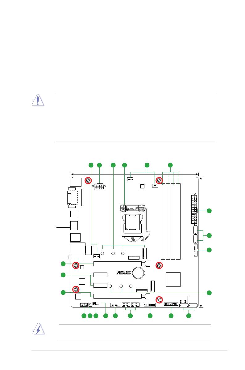
1.2 Motherboard overview
Place this
side towards
the rear of the
chassis
PRIME Z270M-PLUS
PCIE SATA
M.2_2
IRST
X4 V V
PCIE SATA
M.2_1
IRST
X4 V V
PCIEX16_1
PCIEX16_2
ALC
887
PCIEX1_1
PCIEX1_2
M.2_1(SOCKET3)
M.2_2(SOCKET3)
Intel
I219V
USB1112 USB1314
AAFP SPDIF_OUT
CLRTC
MONO_OUT
EATXPWR
BATTERY
Super
I/O
2280 2260 2242
2280 2260 2242
KBMS
DVI
VGA
23.9cm(9.4in)
DDR4 DIMM_A1 (64bit, 288-pin module)
DDR4 DIMM_A2 (64bit, 288-pin module)
DDR4 DIMM_B1 (64bit, 288-pin module)
DDR4 DIMM_B2 (64bit, 288-pin module)
LAN_USB910
USB3_78
USB3_C5
HDMI
CPU_FAN
CHA_FAN1
CHA_FAN2
24.4cm(9.6in)
LGA1151
DIGI
+VRM
COM
EATX12V
USB3_12
USB3_34
Intel®
Z270
128Mb
BIOS
PANEL
AUDIO
SATA6G_6
SATA6G_5
SATA6G_1SATA6G_2
LANGuard
31 2 4 51
87 61213
14
11 10
2
7
3
6
9
16
15
15
1-2 Chapter 1: Product introduction
1.2.1 Layout contents
Connectors/Jumpers/Slots/LED Page
1. CPUandchassisfanconnectors(4-pinCPU_FAN,4-pinCHA_FAN1/2) 1-2
2. ATXpowerconnectors(24-pinEATXPWR,8-pinEATX12V) 1-2
3. M.2 Socket3 1-3
4. Intel®LGA1151CPUsocket 1-3
5. DDR4DIMMslots 1-3
6. Intel®Z270SerialATA6.0Gb/sports(SATA6G_1~4) 1-3
7. USB3.0connectors(20-1pinUSB3_12,USB3_34) 1-4
8. Systempanelconnector(20-5pinPANEL) 1-4
9. USB2.0connectors(10-1pinUSB1112,USB1314) 1-4
10. SerialPortConnector(10-1pinCOM) 1-5
11. ClearRTCRAM(2-pinCLRTC) 1-5
12. Digitalaudioconnector(4-1pinSPDIF_OUT) 1-5
13. Mono out header(2-pin MONO_OUT) 1-5
14 Frontpanelaudioconnector(10-1pinAAFP) 1-5
15 PCIExpress3.0/2.0x16slots 1-6
16 PCIExpress3.0/2.0x1slots 1-6
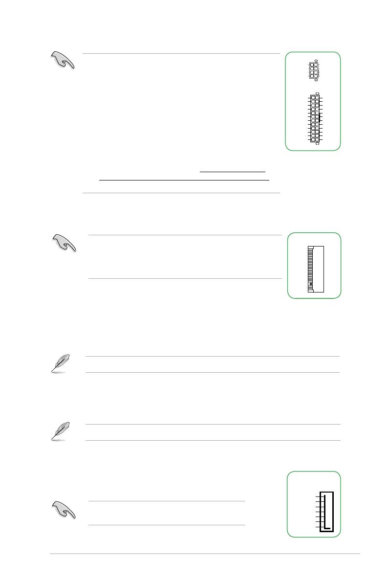
2. ATX power connectors (24-pin EATXPWR, 8-pin EATX12V)
TheseconnectorsareforATXpowersupplyplugs.Thepowersupplyplugsare
designedtottheseconnectorsinonlyoneorientation.Findtheproperorientationand
pushdownrmlyuntiltheconnectorscompletelyt.
1. CPU and chassis fan connectors (4-pin CPU_FAN, 4-pin CHA_FAN1/2)
Connectthefancablestothefanconnectorsonthemotherboard,ensuringthatthe
black wire of each cable matches the ground pin of the connector.
CHA FAN PWM
CHA FAN IN
CHA FAN PWR
GND
CPU_FAN
CPU FAN PWM
CPU FAN IN
CPU FAN PWR
GND
CHA_FAN
Do not forget to connect the fan cables to the fan connectors.
Insufcientairowinsidethesystemmaydamagethe
motherboard components. These are not jumpers! Do not place
jumpercapsonthefanconnectors!TheCPU_FANconnector
supportsaCPUfanofmaximum1A(12W)fanpower.
ASUS PRIME Z270M-PLUS 1-3
•
WerecommendthatyouuseanEATX12VSpecication
2.0-compliantpowersupplyunit(PSU)withaminimumof300W
powerrating.ThisPSUtypehas24-pinand8-pinpowerplugs.
•
DONOTforgettoconnectthe8-pinEATX+12Vpowerplug.
Otherwise,thesystemwillnotbootup.
• WerecommendthatyouuseaPSUwithhigherpoweroutput
whenconguringasystemwithmorepower-consumingdevices
orwhenyouintendtoinstalladditionaldevices.Thesystemmay
become unstable or may not boot up if the power is inadequate.
•
If you are uncertain about the minimum power supply
requirementforyoursystem,refertotheRecommended
PowerSupplyWattageCalculatorathttp://support.asus.com/
PowerSupplyCalculator/PSCalculator.aspx?SLanguage=en-us for
details.
EATX12V
+12V DC
+12V DC
+12V DC
+12V DC
GND
GND
GND
GND
EATXPWR
PIN 1
PIN 1
GND
+5 Volts
+5 Volts
+5 Volts
-5 Volts
GND
GND
GND
PSON#
GND
-12 Volts
+3 Volts
+3 Volts
+12 Volts
+12 Volts
+5V Standby
Power OK
GND
+5 Volts
GND
+5 Volts
GND
+3 Volts
+3 Volts
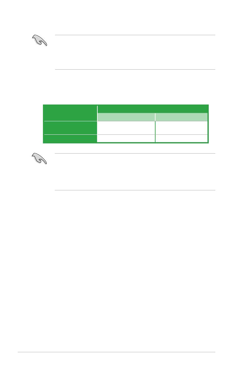
5. DDR4 DIMM slots
Install2GB,4GB,8GB,and16GBunbufferednon-ECCDDR4DIMMsintothese
DIMM sockets.
Formoredetails,refertoSystem memory.
3. M.2 socket 3
ThesesocketsallowyoutoinstallanM.2(NGFF)SSDmodule.
6. Intel® Z270 Serial ATA 6.0Gb/s ports (7-pin SATA6G_1~4)
TheseportsconnecttoSerialATA6.0Gb/sharddiskdrivesvia
SerialATA6.0Gb/ssignalcables.
GND
RSATA_TXP
RSATA_TXN
GND
RSATA_RXN
RSATA_RXP
GND
SATA6G
Whenusinghot-plugandNCQ,settheSATA Mode
SelectionitemintheBIOSto[AHCI].
M.2(SOCKET3)
4. Intel® LGA1151 CPU socket
Install Intel®LGA1151CPUintothissurfacemountLGA1151socket,
whichisdesignedfor7th/6thGenerationIntel®Core™i7/i5/i3,
Pentium®,andCeleron® processors.
Formoredetails,refertoCentral Processing Unit (CPU).
• ThesesocketssupportMKeyand2242/2260/2280storage
devices.
• WhenadeviceinSATAmodeisinstalledontheM.2_1socket,
SATA_1portcannotbeused.

1-4 Chapter 1: Product introduction
8. System panel connector (20-5 pin PANEL)
Thisconnectorsupportsseveralchassis-mountedfunctions.
• SystempowerLED(2-pinPWR_LED)
These2-pinconnectorsareforthesystempowerLED.
ConnectthechassispowerLEDcabletotheseconnectors.
ThesystempowerLEDlightsupwhenyouturnonthe
systempower,andblinkswhenthesystemisinsleepmode.
• HarddiskdriveactivityLED(2-pinHDD_LED)
This2-pinconnectorisfortheHDDActivityLED.Connect
theHDDActivityLEDcabletothisconnector.TheHDDLED
lightsuporasheswhendataisreadfromorwrittentothe
HDD.
• Systemwarningspeaker(4-pinSPEAKER)
This4-pinconnectorisforthechassis-mountedsystem
warning speaker. The speaker allows you to hear system
beeps and warnings.
• ATXpowerbutton/soft-offbutton(2-pinPWR_SW)
This connector is for the system power button.
• Resetbutton(2-pinRESET)
This 2-pin connector is for the chassis-mounted reset button
for system reboot without turning off the system power.
PLED+
PLED-
PWRBTN#
GND
+5V
GND
GND
Speaker
HDD_LED+
HDD_LED-
GND
RSTCON#
NC
PLED+
PLED-
PIN 1
+PWR_LED-
+PWR_LED-
SPEAKER
PANEL
+HDD_LED-
PWR_SW
RESET
7. USB 3.0 connectors (20-1 pin USB3_12, USB3_34)
TheseconnectorsallowyoutoconnectaUSB3.0
moduleforadditionalUSB3.0frontorrearpanelports.
WithaninstalledUSB3.0module,youcanenjoyall
thebenetsofUSB3.0includingfasterdatatransfer
speedsofupto5Gbps,fasterchargingtimeforUSB-
chargeabledevices,optimizedpowerefciencyand
backwardcompatibilitywithUSB2.0.
USB3_12
GND
IntA_P1_D+
IntA_P1_D-
GND
IntA_P1_SSTX+
IntA_P1_SSTX-
GND
IntA_P1_SSRX+
IntA_P1_SSRX-
USB3+5V
PIN 1
IntA_P2_D+
IntA_P2_D-
GND
IntA_P2_SSTX+
IntA_P2_SSTX-
GND
IntA_P2_SSRX+
IntA_P2_SSRX-
USB3+5V
9. USB 2.0 connectors (10-1 pin USB1112, USB1314)
TheseconnectorsareforUSB2.0ports.ConnecttheUSBmodule
cabletoanyoftheseconnectors,theninstallthemoduletoaslot
openingatthebackofthesystemchassis.TheseUSBconnectors
complywithUSB2.0specicationsandsupportupto480Mbps
connection speed.
Neverconnecta1394cabletotheUSBconnectors.Doingso
will damage the motherboard!
USB+5V
USB_P11-
USB_P11+
GND
NC
USB+5V
USB_P12-
USB_P12+
GND
USB1112
PIN 1

ASUS PRIME Z270M-PLUS 1-5
To erase the RTC RAM:
1. TurnOFFthecomputerandunplugthepowercord.
2. Useametalobjectsuchasascrewdrivertoshortthetwopins.
3. PlugthepowercordandturnONthecomputer.
4. Holddownthe<Del>keyduringthebootprocessandenterBIOS
setup to re-enter data.
Ifthestepsabovedonothelp,removetheonboardbatteryandshortthetwopinsagainto
cleartheCMOSRTCRAMdata.AfterclearingtheCMOS,reinstallthebattery.
CLRTC
+3V_BAT
GND
PIN 1
12. Digital audio connector (4-1 pin SPDIF_OUT)
ThisconnectorisforanadditionalSony/PhilipsDigitalInterface(S/
PDIF)port.ConnecttheS/PDIFOutmodulecabletothisconnector,
then install the module to a slot opening at the back of the system
chassis.
SPDIF_OUT
+5V
SPDIFOUT
GND
10. Serial port connector (10-1 pin COM)
Thisconnectorisforaserial(COM)port.Connecttheserialport
modulecabletothisconnector,theninstallthemoduletoaslot
opening at the back of the system chassis.
PIN 1
COM
DCD
TXD
GND
RTS
RI
RXD
DTR
DSR
CTS
11. Clear RTC RAM (2-pin CLRTC)
ThisheaderallowsyoutocleartheRealTimeClock(RTC)RAMinCMOS.Youcan
cleartheCMOSmemoryofdate,andsystemsetupparametersbyerasingtheCMOS
RTCRAMdata.TheonboardbuttoncellbatterypowerstheRAMdatainCMOS,which
include system setup information such as system passwords.
13. Mono out header (2-pin MONO_OUT)
Thisinternalmonooutheaderallowsconnectiontoaninternal,low
power speaker for basic system sound capability. The subsystem is
capableofdrivingaspeakerloadof4Ohmsat2Watts(rms).
R_OUT-
R_OUT+
PIN 1
MONO_OUT
14. Front panel audio connector (10-1 pin AAFP)
This connector is for a chassis-mounted front panel audio
I/OmodulethatsupportsHDAudio.Connectoneendof
thefrontpanelaudioI/Omodulecabletothisconnector.
AAFP
AGND
NC
SENSE1_RETUR
SENSE2_RETUR
PORT1 L
PORT1 R
PORT2 R
SENSE_SEND
PORT2 L
HD-audio-compliant
pin definition
PIN 1
AGND
NC
NC
NC
MIC2
MICPWR
Line out_R
NC
Line out_L
Legacy AC’97
compliant definition
1-6 Chapter 1: Product introduction
15. PCI Express 3.0/2.0 x16 slots
ThismotherboardsupportstwoPCIExpress3.0/2.0x16graphiccardsthatcomplywith
thePCIExpressspecications.
VGAconguration PCI Express operating mode
PCIe 3.0 x16_1 (gray) PCIe 3.0 x16_2
Single VGA/PCIe card x16(Recommendedforsingle
VGAcard) N/A
Dual VGA/PCIe cards x16 x4
• InsingleVGAcardmode,usethePCIe3.0x16_1slot(gray)foraPCIExpressx16
graphics card to get better performance.
• WerecommendthatyouprovidesufcientpowerwhenrunningCrossFireX™mode.
• ConnectachassisfantothemotherboardconnectorlabeledCHA_FAN1/2when
usingmultiplegraphicscardsforbetterthermalenvironment.
16. PCI Express 3.0/2.0 x1 slots
ThismotherboardhastwoPCIExpress3.0/2.0x1slotsthatsupportPCIExpress
x1networkcards,SCSIcards,andothercardsthatcomplywiththePCIExpress
specications.
• Werecommendthatyouconnectahigh-denitionfrontpanelaudiomoduletothis
connectortoavailofthemotherboard’shigh-denitionaudiocapability.
• Ifyouwanttoconnectahigh-denitionfrontpanelaudiomoduletothisconnector,set
the Front Panel TypeitemintheBIOSsetupto[HD].Bydefault,thisconnectorisset
to[HD].
ASUS PRIME Z270M-PLUS 1-7
A B C D E F G H
HDAudioController shared – – – – – – –
XHCI shared – – – – – – –
SATAController shared – – – – – – –
LANController shared – – – – – – –
PCIEx1_1 – – shared – – – – –
PCIEx1_2 – – – shared – – – –
PCIEx16_1 shared – – – – – – –
PCIEx16_2 shared – – – – – – –
M.2_1 shared – – – – – – –
M.2_2 shared – – – – – – –
IRQ assignments for this motherboard
WhenusingPCIcardsonsharedslots,ensurethatthedriverssupport“ShareIRQ”orthat
thecardsdonotneedIRQassignments.Otherwise,conictswillarisebetweenthetwoPCI
groups,makingthesystemunstableandthecardinoperable.

1-8 Chapter 1: Product introduction
1.2.2 Rear panel connectors
1. PS/2 Mouse port (green).ThisportisforaPS/2mouse.
2. Video Graphics Adapter (VGA) port.This15-pinportisforaVGAmonitororother
VGA-compatibledevices.
3. LAN (RJ-45) port.ThisportallowsGigabitconnectiontoaLocalAreaNetwork(LAN)
throughanetworkhub.RefertothetablebelowfortheLANportLEDindications.
24 53
6
10 8 7
1
12 11 9
LAN port
Speed
LED
Activity Link
LED
LAN port LED indications
4. Line In port (light blue).Thisportconnectsthetape,CD,DVDplayer,orotheraudio
sources.
5. Line Out port (lime).Thisportconnectsaheadphoneoraspeaker.In4.1-channel,
5.1-channel,and7.1-channelcongurations,thefunctionofthisportbecomesFront
SpeakerOut.
6. Microphone port (pink). This port connects a microphone.
Refertotheaudiocongurationtableforthefunctionoftheaudioportsin2.1,4.1,5.1,or
7.1-channelconguration.
Activity/Link LED Speed LED
Status Description Status Description
Off Nolink OFF 10Mbps connection
Orange Linked ORANGE 100Mbps connection
Orange(Blinking) Dataactivity GREEN 1Gbps connection
Orange(Blinking
thensteady)
Readytowake
upfromS5mode
ASUS PRIME Z270M-PLUS 1-9
7. USB 2.0 portsThesefour4-pinUniversalSerialBus(USB)portsareforUSB2.0/1.1
devices.
8. USB 3.0 ports.Thesefour9-pinUniversalSerialBus(USB)portsconnecttoUSB
3.0/2.0devices.
• DuetoUSB3.0controllerlimitations,USB3.0devicescanonlybeusedundera
Windows®OSenvironmentandafterUSB3.0driverinstallation.
• ThepluggedUSB3.0devicemayrunonxHCIorEHCImode,dependingonthe
operatingsystem’ssetting.
• USB3.0devicescanonlybeusedfordatastorage.
• WestronglyrecommendthatyouconnectUSB3.0devicestoUSB3.0portsforfaster
andbetterperformancefromyourUSB3.0devices.
9. HDMI port.ThisportisforaHigh-DenitionMultimediaInterface(HDMI)connector,
andisHDCPcompliantallowingplaybackofHDDVD,Blu-ray,andotherprotected
content.
10. USB 5Gb/s Type C port.This24-pinUniversalSerialBus(USB)portisforUSB
(TypeC)devices.
11. DVI-D port.ThisportisforanyDVI-Dcompatibledevice.
DVI-DcannotbeconvertedtooutputfromRGBSignaltoCRTandisnotcompatiblewith
DVI-I.
12. PS/2 keyboard port (purple).ThisportisforaPS/2keyboard.
Audio2.1,4.1,5.1or7.1-channelconguration
Port Headset
2.1-channel 4.1-channel 5.1-channel 7.1-channel
LightBlue
(Rearpanel) Line In RearSpeakerOut RearSpeakerOut RearSpeakerOut
Lime(Rearpanel) LineOut FrontSpeakerOut FrontSpeakerOut FrontSpeakerOut
Pink(Rearpanel) Mic In Mic In Bass/Center Bass/Center
Lime(Frontpanel) ———SideSpeakerOut
Tocongurean7.1-channelaudiooutput:
UseachassiswithHDaudiomoduleinthefrontpaneltosupportan7.1-channel
audio output.
1-10 Chapter 1: Product introduction
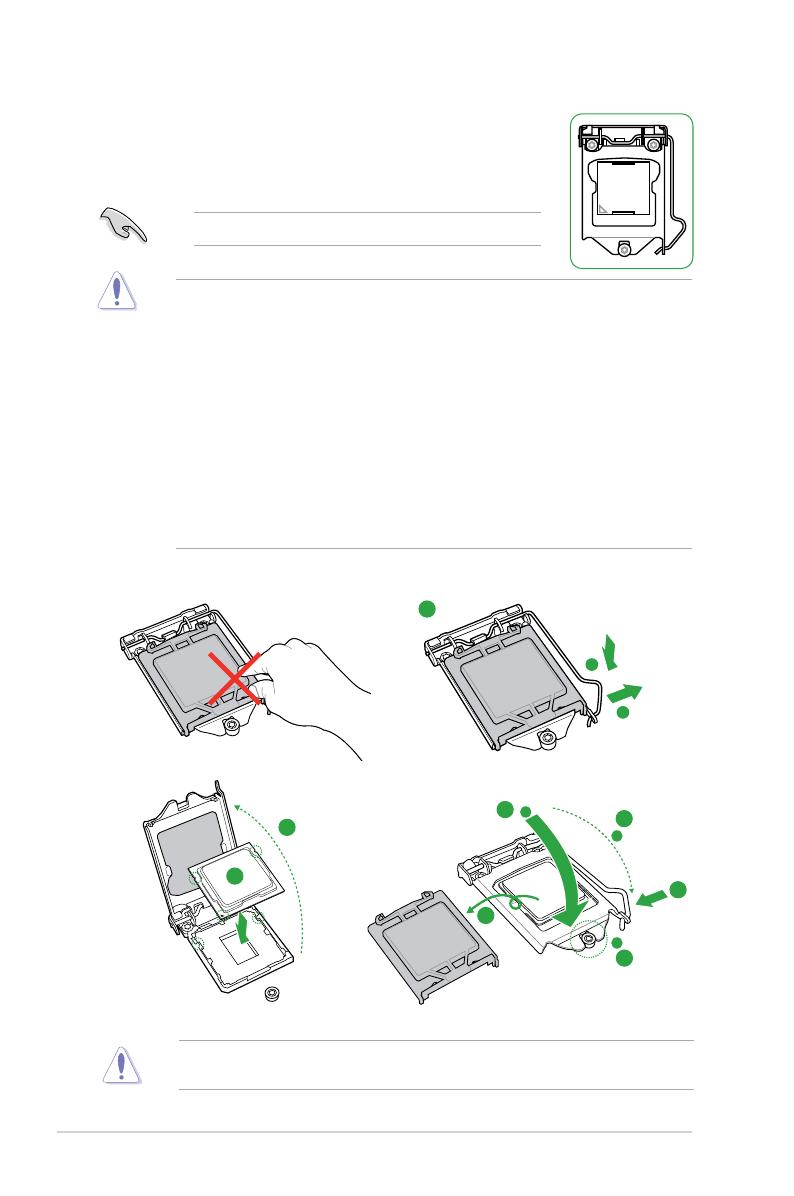
1.3 Central Processing Unit (CPU)
ThismotherboardcomeswithasurfacemountLGA1151socket
designedfor7th/6thGenerationIntel®Core™i7/i5/i3,Pentium®,and
Celeron® processors.
UnplugallpowercablesbeforeinstallingtheCPU.
• EnsurethatyouinstallthecorrectCPUdesignedfortheLGA1151socketonly.DO
NOTinstallaCPUdesignedforLGA1150,LGA1155andLGA1156socketsonthe
LGA1151socket.
• Uponpurchaseofthemotherboard,ensurethatthePnPcapisonthesocketand
the socket contacts are not bent. Contact your retailer immediately if the PnP cap
ismissing,orifyouseeanydamagetothePnPcap/socketcontacts/motherboard
components.
• Keepthecapafterinstallingthemotherboard.ASUSwillprocessReturnMerchandise
Authorization(RMA)requestsonlyifthemotherboardcomeswiththecaponthe
LGA1151socket.
• Theproductwarrantydoesnotcoverdamagetothesocketcontactsresultingfrom
incorrectCPUinstallation/removal,ormisplacement/loss/incorrectremovalofthePnP
cap.
Installing the CPU
1
4
ApplytheThermalInterfaceMaterialtotheCPUheatsinkandCPUbeforeyouinstallthe
heatsink and fan if necessary.
2
3
A
B
A
B
C
D
5
4
4
5
/